Suros ATEC Sapphire Unit User manual

Suros Surgical Systems, Inc. | 6100 Technology Center Drive | Indianapolis, IN 46278 USA
www.SurosSurgical.com | [email protected] | 877.887.8767
Operator’s Manual

Copyright © 2006 Suros Surgical Systems, Inc. ATEC and Suros Compassionate Technologies are trademarks or registered
trademarks of Suros Surgical Systems, Inc. in the United States and other countries. All rights reserved.
Covered by one or more of the following patents and other patents pending: 6,758,824 and 6,638,235.
LIT417:RevA

Congratulations!
Thank you for purchasing the ATEC®
Breast Biopsy and Excision System:
Sapphire™ unit.
Contents
Precautions .......................................................................................1
Warnings and Cautions ....................................................................1
Introduction ......................................................................................4
Indications ........................................................................................4
Contraindications .............................................................................4
Components .....................................................................................6
Console Controls and Functions ......................................................9
ATEC® Breast Biopsy and Excision System:
Sapphire™ Unit Set Up ...................................................................10
ATEC® Breast Biopsy and Excision System:
Sapphire™ Unit Check Out .............................................................14
Using the ATEC® Breast Biopsy and Excision System:
Sapphire™ Unit ...............................................................................15
Performing a Biopsy Using MRI Guidance ...................................15
Performing a Biopsy Using STX or U/S Guidance .......................16
Performing a Biopsy Using a Stereotactic Adapter .......................17
ATEC® Handpiece Operating Instructions .....................................18
Troubleshooting .............................................................................19
Warranty .........................................................................................21
Service and Maintenance ...............................................................22
Cleaning Instructions .....................................................................26
Owner’s Record .............................................................................27
Specifications .................................................................................28
Important Contact Information .....................................................30

ATEC® Breast Biopsy and Excision System: Sapphire™ Unit Operator’s Manual
Precautions
Please read all contents of the Operator’s Manual for your ATEC® Breast Biopsy and Excision System:
Sapphire™ unit prior to installation and operation. Follow all warnings and instructions as stated in
this manual and retain for future reference. Physicians should inform patients about all potential risks
and adverse events discussed in this manual with respect to the use of the ATEC® Breast Biopsy and
Excision System: Sapphire™ unit.
As used below, the term “Suros™” means Suros Surgical Systems, Inc., a Delaware corporation. As
used below, the term “ATEC® Breast Biopsy and Excision System: Sapphire™ unit” means the ATEC
Sapphire™ console unit and all available ATEC® Breast Biopsy and Excision System components, as
more fully described in the Components section below (unless the context dictates otherwise).
v Should any object or liquid fall into the ATEC Sapphire™ console, unplug the console
and have it checked by qualified personnel before operating it any further.
v Unplug the console from the electrical outlet if it is not to be used for several days
or an extended period of time.
v Allow adequate air circulation around the console to prevent internal heat build-up. Do
not place the console on surfaces or near materials that may block the ventilation openings.
v Do not install the console in a location near heat sources such as radiators or air ducts,
or in a place subject to direct sunlight, excessive dust, mechanical vibration or shock.
v To keep the console looking new, periodically clean it with a soft cloth. Stubborn stains
may be removed with a cloth lightly dampened with a mild detergent solution. Never
use strong solvents or abrasive cleansers since these will damage the console casing.
The console should only be cleaned after the power cord is disconnected from the power
outlet and the console.
v Do not place the console on an unstable surface. The console may fall, causing serious
injury and damage to the appliance. Quick stops, excessive force and uneven surfaces
may cause the console to overturn.
Warnings and Cautions
Warnings
v THE COMPONENTS OF THE ATEC® BREAST BIOPSY AND EXCISION
SYSTEM: SAPPHIRE™ UNIT ARE FOR USE ONLY BY QUALIFIED MEDICAL
PERSONNEL TRAINED IN THEIR USE AND APPLICATION. Qualified medical
personnel should perform a test of the ATEC® Breast Biopsy and Excision System:
Sapphire™ unit prior to each procedure or prior to each time a new single patient use
disposable is attached to the console.
v To prevent fire or shock hazard, do not expose the console to rain or moisture.
v To prevent shock hazard, do not use the console’s polarized plug with a receptacle
or other outlet unless the blades can be fully inserted to prevent blade exposure.
1

ATEC® Breast Biopsy and Excision System: Sapphire™ Unit Operator’s Manual
v Do not use the console’s polarized plug with an extension cord.
v Use only disposables that are manufactured by Suros. Use of any other disposables may
result in damage to the console and unintended injury to the patient or unacceptable
clinical results and shall void any warranty provided by Suros herein.
v Only Suros-approved accessory equipment and components shall be used with the ATEC®
Breast Biopsy and Excision System: Sapphire™ unit. Use of the ATEC® Breast Biopsy and
Excision System: Sapphire™ unit with unauthorized accessory equipment and components
shall void any warranty provided by Suros herein.
v All disposables associated with the ATEC® Breast Biopsy and Excision System: Sapphire™
unit are intended for single patient use and are not intended for resterilization and
subsequent reuse. Dispose of all single patient use instruments after opening and use.
v Do not resterilize any ATEC®
Breast Biopsy and Excision System: Sapphire™ unit single
patient use instrument or accessory. Resterilization may compromise the integrity and
mechanical function of the instrument or accessory, which may result in unintended injury
to the patient or unacceptable clinical results.
v DANGER: There is a small risk of explosion if the ATEC® Breast Biopsy and Excision
System: Sapphire™ unit is used in the presence of flammable anesthetics or other explosive gases.
v The ATEC® Breast Biopsy and Excision System: Sapphire™ unit console should only be
opened or serviced by Suros or qualified personnel who have been trained and certified by
Suros Surgical Systems, Inc.
Cautions
v Console not intended for use in the MRI suite.
v Instruments or devices which come into contact with bodily fluids may require special
disposal handling to prevent biological contamination.
v Grounding reliability can only be achieved when the console is connected to an equivalent
receptacle marked “Hospital Grade.”
v The console should not touch other electrical equipment during use.
v The console can radiate radio frequency energy and, if not installed and used in
accordance with the instructions, may cause harmful interference to other devices in the
vicinity. However, there is no guarantee that interference will not occur in a particular
installation. If the console does cause harmful interference to other devices, which can be
determined by turning the console off and on, the user is encouraged to try to correct the
interference by one or more of the following measures:
o Reorient or relocate the receiving device.
o Increase the separation between the equipment.
o Connect the console to an outlet on a circuit different from that to which the other
device(s) are connected.
o Consult Suros for technical help.
v Damage to the power cord may cause a fire or shock hazard. When unplugging the
power cord, please hold by the plug and remove it carefully. Do not damage or modify
the console power cord.
v When the console is not being used, turn off all power switches and place the console
in a location where it will not be damaged.
2

ATEC® Breast Biopsy and Excision System: Sapphire™ Unit Operator’s Manual
3
v Do not place the console on an unstable surface. The console may fall, causing serious
injury and damage to the unit. Quick stops, excessive force and uneven surfaces may
cause the console to overturn.
v Some ATEC® Breast Biopsy and Excision System: Sapphire™ unit consoles may include
settings specific to higher altitudes. Please contact Suros Customer Support or your
distributor if you move your console to a significantly different physical address.
v If you are a Suros customer in the U.S. or in Canada, consult your Suros Sales
Representative or Suros Customer Support if you cannot correct a problem using
this Operator’s Manual. If you are an international customer, please contact your
distributor directly with questions, comments and/or technical service issues.
Symbols
The MR within a triangle is intended to alert the user that a component
or components of the system are “MRI Conditional” and may be brought
into an MRI suite.

ATEC® Breast Biopsy and Excision System: Sapphire™ Unit Operator’s Manual
Introduction
This manual is written for medical personnel who will be responsible for operating the ATEC® Breast
Biopsy and Excision System: Sapphire™ unit. It is extremely important that the operator read and
thoroughly understand the contents of this manual, be trained by a qualified applications specialist,
and follow the instructions contained herein for reliable, safe and efficient operation of the product.
CAUTION: Federal law restricts this device to sale by or on the order of a physician pursuant
to C.F.R. 801.109(b)(1).
ATEC® Users in the United States and Canada
All users of the ATEC® Breast Biopsy and Excision System: Sapphire™ unit in the United States
and Canada should contact their Suros Sales Representative or the Suros Customer Service
Department for questions, comments, and/or technical service issues.
International ATEC® Users
All international users of the ATEC® Breast Biopsy and Excision System: Sapphire™ unit should
contact their distributor directly with questions, comments, and/or technical service issues.
Indications
v The ATEC® Breast Biopsy and Excision System is indicated to provide breast tissue samples for
diagnostic sampling of breast abnormalities. The ATEC® Breast Biopsy and Excision System is
intended to provide breast tissue for histologic examination with partial or complete removal of
the imaged abnormality. The extent of histologic abnormality cannot be reliably determined from
its mammographic appearance. Therefore, the extent of removal of the imaged evidence of an
abnormality does not predict the extent of removal of histologic abnormality, e.g., malignancy.
When the sampled abnormality is not histologically benign, it is essential that the tissue margins
be examined for completeness of removal using standard surgical procedure.
Contraindications
v The ATEC® Breast Biopsy and Excision System: Sapphire™ unit is for diagnostic use only
and is NOT indicated for therapeutic use. The ATEC® Breast Biopsy and Excision System:
Sapphire™ unit is NOT intended to be used outside of the standards, specifications and
limitations for the ATEC® Breast Biopsy and Excision System: Sapphire™ unit as outlined
in this manual and other related materials.
v The ATEC® Breast Biopsy and Excision System: Sapphire™ unit is contraindicated for those
patients where increased risk or complications may be associated with biopsy based on the
physician’s judgment. Patients receiving anticoagulant therapy or who may have bleeding
disorders may be at increased risk of procedural complications.
4

ATEC® Breast Biopsy and Excision System: Sapphire™ Unit Operator’s Manual
Notes on the MRI Environment
v The ATEC® Breast Biopsy and Excision System: Sapphire™ unit may be used to perform
biopsies under ultrasound, stereotactic or MRI guidance.
v The ATEC® Breast Biopsy and Excision System: Sapphire™ unit console is not intended
for use in the MRI suite. The ATEC® Breast Biopsy and Excision System: Sapphire™ unit
console must reside outside of the MRI suite.
v The ATEC® footswitch, ATEC® MRI handpiece and ATEC® Introducer Localization System
are safe to use in the MRI suite.
v Suros offers a variety of disposable handpiece configurations. However, when performing
MRI-guided breast biopsy procedures, an ATEC® MRI handpiece must be used. The
ATEC® Introducer Localization System is available for localizing the area targeted
for biopsy. The ATEC® MRI handpiece and ATEC® Introducer Localization System is
specifically designed for use in the MRI environment. ATEC® handpieces designed for use
with MRI guidance are compatible with the red receptacle marked “MRI” on the console.
v ATEC® handpieces designed for use with stereotactic (STX) and ultrasound (US)
guidance are compatible with the red receptacle marked “US/STX” on the console.
v The particular handpiece selected for use with ultrasound or stereotactic guidance
depends on user preference and the type of stereotactic system being used. Please refer
to the Disposable Component Selection section of this manual for additional guidance.
v A complete list of ATEC® handpieces and other disposables suited for MRI, stereotactic
or ultrasound-guided biopsy procedures is included in the Components section.
5

ATEC® Breast Biopsy and Excision System: Sapphire™ Unit Operator’s Manual
Components
Below is a list of available components for the ATEC® Breast Biopsy and Excision System:
Sapphire™ unit.
Capital Equipment (multiple patient use)
ATEC® Breast Biopsy and Excision System: Sapphire™ unit
ATEC® Footswitch
ATEC® Power Cord
ATEC® Vacuum Line Assembly
ATEC® Stereotactic Adapter for use on stereotactic systems
Single Patient Use Disposable Components for
Procedures Using Stereotactic or Ultrasound Guidance
ATEC® Handpiece
ATEC® Suction Canister
ATEC® Tissue Filters
ATEC® Remote Tissue Filter Adapter (RTFA)
The RTFA is for use with Lorad® upright stereotactic systems and Siemens stereotactic systems.
ATEC® Needle Guides
For use with stereotactic systems.
Single Patient Use Disposable Components
for MRI-Guided Procedures
ATEC® MRI Handpiece
ATEC® Introducer Localization System
ATEC® Suction Canister
ATEC® Tissue Filters
6

ATEC® Breast Biopsy and Excision System: Sapphire™ Unit Operator’s Manual
Capital Equipment (multiple patient use)
MRI
Guided Biopsy
Procedures
Ultrasound
Guided Biopsy
Procedures
Stereotactic
Guided Biopsy
Procedures
ATEC® Breast Biopsy and
Excision System: Sapphire™ unit v v v
ATEC® Footswitch v v v
ATEC® Power Cord v v v
ATEC® Vacuum Line Assembly v v v
ATEC® Stereotactic Adapter v
Single Patient Use Disposable Components
MRI
Guided Biopsy
Procedures
Ultrasound
Guided Biopsy
Procedures
Stereotactic
Guided Biopsy
Procedures
ATEC® MRI Handpiece v
ATEC® Introducer Localization System v
ATEC® Handpiece v v
ATEC® Suction Canister with Lid v v v
ATEC® Tissue Filters optional optional optional
ATEC® Remote Tissue Filter Adapter
(RTFA) optional
ATEC® Needle Guides v
7

ATEC® Breast Biopsy and Excision System: Sapphire™ Unit Operator’s Manual
Disposable Handpiece Selection
by Catalog Number
Suros offers a variety of ATEC® handpiece configurations. As the chart below indicates, the specific
handpiece selected depends on user preference (9GA vs 12GA cutting cannula) and the type of imaging
equipment being used. Please note that Suros offers two specialized handpieces with a “petite” aperture
for stereotactic and MRI-guided biopsy procedures. The standard petite handpiece (ATEC0912-12) for
stereotactic-guided breast biopsy allows for breast compression to as little as 20mm. The ATEC MRI
Access™ petite handpiece (ATEC0914-12MR) for MRI-guided breast biopsy features a hemispherical
needle tip and allows for breast compression to as little as 16mm.
Please refer to the Suros Website at www.SurosSurgical.com for an updated list of disposable handpiece offerings.
ATEC® handpiece catalog numbers use the following number nomenclature:
ATEC® Cutting Cannula Needle Gauge / Needle Length (cm) / Aperture Size (mm).
For example, an ATEC0912-20 handpiece is 12cm long, with a 9GA cutting cannula and a 20mm aperture.
ATEC® Compatiblity Chart
Equipment Type
Handpiece with
12GA Cutting
Cannula
Handpiece with
9GA Cutting
Cannula
Handpiece with
Petite Aperture
ATEC
®
Stereotactic
Adapter Model
Needle
Guide
Lorad Prone
Stereotactic Systems ATEC1212-20 ATEC0912-20 ATEC0912-12 ATEC STX-1
or ATEC STX-2
NG09
NG12
Lorad Upright
Stereotactic Systems
(An ATEC® Remote Tissue
Filter Adapter should be used
with each handpiece.)
ATEC1212-20 ATEC0912-20 ATEC0912-12 ATEC STX-2 NG09
NG12
Fischer
Stereotactic Systems
Frontal Approach
ATEC1209-20 ATEC0909-20 ATEC0909-12 ATEC STX-Fischer
or ATEC STX-2F
NG09F
NG12F
Fischer
Stereotactic Systems
Lateral Approach
N/A ATEC0914-20 Compression limit
is not relevant
ATEC STX-Fischer
or ATEC STX-2F NG09F
Instrumentarium
Stereotactic Systems N/A ATEC0914-20 Compression limit
is not relevant ATEC STX-2 NG09F
GE
Stereotactic Systems
Lateral Approach
N/A ATEC0914-20 Compression limit
is not relevant ATEC STX-2 NG09F
GE
Stereotactic Systems
Vertical Approach
ATEC1212-20 ATEC0912-20 ATEC0912-12 N/A NG09F
NG12F
Siemens
Stereotactic Systems
(An ATEC® Remote Tissue
Filter Adapter should be used
with each handpiece.)
ATEC1212-20 ATEC0912-20 ATEC0912-12 ATEC STX-2 NG09F
NG12F
Ultrasound
Handheld Procedures ATEC1212-20 ATEC0912-20 ATEC0912-12 N/A N/A
MRI Procedures N/A ATEC0914-20MR
plus ILS0914-20
ATEC0914-12MR
plus ILS0914-12 N/A Included
in ILS
8

ATEC® Breast Biopsy and Excision System: Sapphire™ Unit Operator’s Manual
Console Controls and Functions
The console user interface panels include controls that enable the user to operate the ATEC® system
and indicator lights that provide additional information about system status. A detailed description
of each component on the user interface can be found below.
Console User Interface
1. Power Switch – Turns power to the console on or off: On = Illuminated green and “|”
Off = Not Illuminated and “O”
2. “Setup” Button – This push button control allows for the self-priming of the system with saline.
When placed in “Set Up” mode, the “Saline PV” (Pinch Valve) is opened and the vacuum is turned on,
allowing insertion of the silicone section of the handpiece saline line into the pinch valve.
3. “Test” Button – This push button control activates the handpiece through one test cycle. The
system will return to “Biopsy” mode upon successful completion of one test cycle.
4. “Biopsy” Button – When placed in “Biopsy” mode, the handpiece is ready for tissue acquisition.
5. “Lavage” Button – When placed in “Lavage” mode, the “Saline PV” is opened and vacuum is
turned on to irrigate and aspirate the biopsy cavity.
6. “Manual Aspiration” Button – When placed in “Manual Aspiration” mode, the “Saline PV” is
closed and the inner cutting cannula is retracted. In this mode, the user can vacuum the biopsy
cavity by depressing the footswitch.
7. “Retest Handpiece” Indicator – Does not illuminate under normal conditions. Flashes red
when “Test” mode is not completed due to pressure failure. Refer to the Troubleshooting section
for suggested steps to diagnose and correct a potential problem.
8. “Return to Setup” Indicator – Does not illuminate under normal conditions. Flashes red when
“Test” mode is not completed due to vacuum failure. Refer to the Troubleshooting section for
suggested steps to diagnose and correct a potential problem.
Left User Interface
14
9
Right User Interface
1. Power Switch – Turns power to the console on or off: On = Illuminated green and “|”
Off = Not Illuminated and “O”
2. “ Setup” Button – This push button control allows for the self-priming of the system with
saline. When placed in “Set Up” mode, the “Saline PV” (Pinch Valve) is opened and the vacuum is
turned on, allowing insertion of the silicone section of the handpiece saline line into the pinch valve.
3. “ Test” Button – This push button control activates the handpiece through one test cycle. The
system will return to “Biopsy” mode upon successful completion of one test cycle.
4. “Biopsy” Button – When placed in “Biopsy” mode, the handpiece is ready for tissue acquisition.
5. “ Lavage” Button – When placed in “Lavage” mode, the “Saline PV” is opened and vacuum is
turned on to irrigate and aspirate the biopsy cavity.
6. “ Manual Aspiration” Button – When placed in “Manual Aspiration” mode, the “Saline PV”
is closed and the inner cutting cannula is retracted. In this mode, the user can vacuum the
biopsy cavity by depressing the footswitch.
7. “ Retest Handpiece” Indicator – Does not illuminate under normal conditions. Flashes red
when “Test” mode is not completed due to pressure failure. Refer to the Troubleshooting
section for suggested steps to diagnose and correct a potential problem.
8. “ Return to Setup” Indicator – Does not illuminate under normal conditions. Flashes red
when “Test” mode is not completed due to vacuum failure. Refer to the Troubleshooting
section for suggested steps to diagnose and correct a potential problem.
13
10
12
11
3
4
5
6
7
8
9
1
2

ATEC® Breast Biopsy and Excision System: Sapphire™ Unit Operator’s Manual
9. “ Vacuum Ready” Indicator – Illuminates solid green when the console has achieved
full vacuum. Flashes green when full vacuum is not achieved within the specified time
frame. If this indicator flashes, refer to the Troubleshooting section for suggested steps
to diagnose and correct a potential problem. The footswitch will not enable the handpiece
to function unless this indicator is illuminated solid green.
10. Vacuum Line Assembly – This is clear tubing that is permanently attached to the console at one
end. The other end has a blue connector that will attach to the ATEC® Suction Canister Lid at the
port labeled “VACUUM.”
11. Red “MRI” Handpiece Receptacle – Attachment site for the MRI handpiece fitting with the
red sleeve.
12. Black Handpiece Receptacle – Attachment site for the handpiece fitting with the black sleeve.
13. Red “US/STX” Handpiece Receptacle – Attachment site for the US/STX handpiece fitting
with the red sleeve.
14. “Saline PV” (Pinch Valve) – Attachment site for the silicone tubing section of the handpiece
saline line. Controls the flow of saline to the handpiece.
ATEC® Breast Biopsy and Excision System:
Sapphire™ Unit Set Up
This section provides information on how to make all necessary connections to set up the ATEC®
Breast Biopsy and Excision System: Sapphire™ unit.
The following connections will be explained:
v ATEC® Power Cord and Circuit Breaker
v ATEC® Footswitch
v ATEC® Vacuum Line Assembly
v ATEC® Handpiece
ATEC® Power Cord Connection and Circuit Breaker
CAUTION: Grounding reliability can only be achieved when this equipment is connected to an
equivalent receptacle marked “Hospital Grade.” Check grounding continuity regularly.
v Connect the ATEC® Power Cord Set into the power cord receptacle on the side panel, as
shown in Figure 1, left side.
Note: The ATEC® Breast Biopsy and Excision System: Sapphire™ unit console was designed to
be used with the Hospital Grade Power Cord Set provided with the console. DO NOT use a
different power cord with the ATEC® Breast Biopsy and Excision System: Sapphire™ unit.
Using a different power cord may create an electrical and fire hazard. DO NOT, under any
circumstances, remove the ground wire or ground plug from any power plug. DO NOT use an
extension cord with this equipment. An adapter may be necessary depending on the outlet used.
10

ATEC® Breast Biopsy and Excision System: Sapphire™ Unit Operator’s Manual
The power cord will connect the ATEC® Breast Biopsy and Excision System: Sapphire™ unit to the
facility power supply (electrical outlet). Note: This is the location of disconnect from the mains
(electrical supply).
Note: Ensure that the power cord is in good condition. A damaged power cord can be an electrical
shock hazard. When unplugging the unit, always grasp the plug at the insertion point and pull
gently. NEVER pull on the cord to unplug the unit.
1. Ratings Chart – Consult this chart if you need any information on the electrical ratings of the
ATEC® Breast Biopsy and Excision System: Sapphire™ unit. This chart also contains the serial
number of your ATEC® Breast Biopsy and Excision System: Sapphire™ unit.
2. Circuit Breaker – Part of the AC Inlet. If the circuit breaker has been tripped, the black
button will not be fl ush and a white dot will be visible. To reset, turn the unit off and allow
for a one-minute “cool down” period before depressing the black button to restart the unit.
3. AC Inlet – Attachment site for the “Hospital Grade” plug and disconnect from the mains
(electrical supply).
4. Instructions Placard Hook – Attachment site for the instructions placard.
5. ATEC® Power Cord
6. ATEC® Power Cord Management Plate
7. ATEC® Footswitch – Activates handpiece.
8. ATEC® Footswitch Cord Management Plate
9. Saline Bag Hook – Attachment site for saline bag (250cc recommended).
10. Casters – All four casters allow for a 360-degree swivel capability and have locking brakes
to help hold the unit in place.
11
Figure 1: Console Electric Connections
Right
Side
Left
Side
3
4
56
7
8
9
1
2
10 10

ATEC® Breast Biopsy and Excision System: Sapphire™ Unit Operator’s Manual
Footswitch Connection
v The footswitch is provided by Suros and should be attached to the right side of the console
upon delivery.
ATEC® Suction Canister Assembly
Once the console has been turned on, the system will generate its own vacuum.
The vacuum connections require that you use an ATEC® Suction Canister from Suros.
v Assemble the suction canister, as shown in Figure 2, and place in the canister holder on
the top of the console in the canister seating area.
v Ensure that the lid and large port cap are secure and sealed to avoid vacuum leaks.
v Plug the vacuum line assembly on the console into the port labeled “VACUUM”
on the suction canister lid.
Note: The ATEC®
Suction Canister is
a single use product
with a recommended
maximum volume
of 400cc.
Figure 2: ATEC® Suction Canister
12

ATEC® Breast Biopsy and Excision System: Sapphire™ Unit Operator’s Manual
Handpiece Connections
Using Aseptic Technique (refer to Figure 3):
v Peel open the saline bag, remove the cap and place the bag on the hook on the right
side of the console.
v Peel open the sterile pack of the disposable handpiece and place tray on the top of the
console. (Leave the protective sheath on handpiece tip.)
v Remove the terminal ends of the 4 lines from the handpiece tray.
o Install the spike to the saline bag and insert the silicone section into the pinch valve
labeled “Saline PV.”
o Plug the red banded line into the receptacle on the console with the red ring.
o Plug the black banded line into the receptacle on the console with the black ring.
o Attach the blue suction fitting to the horizontal port marked “PATIENT” on the side
of the suction canister lid.
Figure 3: Vacuum and Handpiece Assembly and Connections
13

ATEC® Breast Biopsy and Excision System: Sapphire™ Unit Operator’s Manual
ATEC® Breast Biopsy and Excision System:
Sapphire™ Unit Check Out
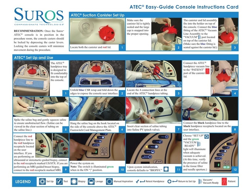
v Power up the system by
switching the green “Power”
switch on the console to the
“|” position. This switch will
illuminate green when “on.”
v The power up or default mode
is “Biopsy.”
v Select the “Set Up” mode. “Set
Up” mode will prime the system
and generate vacuum.
When the console is in “Set Up”
mode, the “Vacuum Ready”
light will illuminate when ample
vacuum is achieved (see Figure
4). If ample vacuum is not
achieved, the “Vacuum Ready”
light will flash to alert the user
to a possible problem. If the
“Vacuum Ready” light flashes,
refer to the Troubleshooting
section of this manual for
suggested steps to diagnose
and correct a potential problem.
v Insert the silicone section of the saline tubing line into
the pinch valve labeled “Saline PV” as shown in Figure 5.
v Verify the flow of saline into the aperture (mouth) and filter
canister of the handpiece.
v The “Vacuum Ready” indicator will illuminate solid green
to verify that vacuum has been attained.
v Select the “Test” mode.
v The handpiece will complete one test cycle. If the “Retest
HP” or “Return to Set Up” indicator begins to flash, refer
to the Troubleshooting section of this manual for suggested
steps to diagnose and correct a potential problem.
v Upon completion of a successful test cycle, the handpiece
will return to “Biopsy” and is ready for tissue acquisition.
Figure 4: ATEC® Breast Biopsy and
Excision System: Sapphire™ Unit
Check Out
14
Figure 5: Saline Pinch
Valve Connection

ATEC® Breast Biopsy and Excision System: Sapphire™ Unit Operator’s Manual
15
Using the ATEC® Breast Biopsy and
Excision System: Sapphire™ Unit
Using the System (MRI)
v When the console is in “Biopsy” mode, depressing the footswitch will activate the vacuum
and operation of the handpiece.
v When the console is in “Lavage” mode, the user can automatically aspirate and irrigate
the biopsy cavity. It is not necessary to depress the footswitch.
v When the console is in “Manual Aspiration” mode, depressing the footswitch allows the
user to independently control aspiration without taking a tissue sample. This function may
be used to vacuum or irrigate the biopsy cavity.
Additional operating instructions for an MRI-guided breast biopsy are outlined below.
Performing a Biopsy Using MRI Guidance
After setting up the ATEC® Breast Biopsy and Excision System per the steps outlined in this
manual or in the ATEC® Easy-Guide Console Instructions Card, MRI-guided breast biopsy
using the ATEC® may be performed by following the steps below:
v Once the area to be biopsied has been identified, prepare the area for biopsy utilizing
standard facility techniques.
v Insert the sterile Needle Guide into the compression grid at the identified target area in
the appropriate “cube.”
v Insert the Introducer Stylet that is hubbed to the Introducer Sheath. The depth stop on the
Introducer Sheath is placed in the appropriate location according to the pre-determined “Z” axis.
v Insert the Introducer Sheath, with the Introducer Stylet, while rotating the sheath / stylet
assembly into and through the Needle Guide to the depth stop, allowing for a pathway
to the target area.
v Remove the stylet from the Introducer Sheath while leaving the Introducer Sheath in place.
v Insert the Localizing Obturator into the sheath.
v With MR image guidance, identify the location of the Localizing Obturator to the area
to be biopsied.
v If location of Localizing Obturator is not accurate, reposition. If it is accurate, continue
to step below.
v Remove Localizing Obturator from introducer sheath.
v Insert and hub the ATEC® handpiece into the Introducer Sheath and to the biopsy site in
preparation for the biopsy to be performed.
v Once the biopsy is complete, remove the ATEC® biopsy handpiece, leaving the Introducer
Sheath in place.
v After imaging to confirm acquisition of the target area and with the Introducer Sheath still
in place, remove the patient from the MRI bore and place a biopsy site marker in the target
area cavity to later identify the biopsy site.

ATEC® Breast Biopsy and Excision System: Sapphire™ Unit Operator’s Manual
Using the ATEC® Breast Biopsy and
Excision System: Sapphire™ Unit
Using the System (Ultrasound or Stereotactic)
v When the console is in “Biopsy” mode, depressing the footswitch will activate the vacuum
and operation of the handpiece.
v When the console is in “Lavage” mode, the user can automatically aspirate and irrigate the
biopsy cavity. It is not necessary to depress the footswitch.
v When the console is in “Manual Aspiration” mode, depressing the footswitch allows the
user to independently control aspiration without taking a tissue sample. This function may
be used to vacuum or irrigate the biopsy cavity.
Additional operating instructions are required for a stereotactic biopsy and a stereotactic
adapter must be utilized. Suros offers four stereotactic adapter models, which are depicted
in Figures 6, 7, 8, and 9.
v Figure 6: ATEC STX-1 (for Lorad prone stereotactic systems)
v Figure 7: ATEC STX-2 (for Lorad upright, GE, Instrumentarium and Siemens systems,
and for International Lorad prone systems)
v Figure 8: ATEC STX-2F (for International Fischer stereotactic systems)
v Figure 9: ATEC STX-Fischer (for Fischer stereotactic systems)
16
Figure 6: ATEC STX-1

ATEC® Breast Biopsy and Excision System: Sapphire™ Unit Operator’s Manual
Performing a Biopsy Using a Stereotactic Adapter
v With the clear protective sleeve covering the outer cannula, slide the ATEC® handpiece
forward onto the stereotactic adapter until the ring on the front of the ATEC® handpiece
engages with the guide ring on the front of the stereotactic adapter.
v Lock the ATEC® handpiece into the stereotactic adapter by sliding the handpiece retaining
clamp into the lock position.
v Remove the protective sleeve covering the outer cannula.
v If it is desirable to “rapid advance” the ATEC® handpiece into the target area, pull the
cocking lever outwards about 80 degrees until there is no further forward movement.
The cocking lever will return by spring action to its at-rest position.
Note: The stereotactic adapter can only be cocked if the handpiece retaining clamp
is in the lock position.
v To “rapid advance” the ATEC® handpiece into the target area, pull the release/firing knob
located on either side of the stereotactic adapter outward a minimum of 1/8” and then push
the knob downward.
v Immediately following the procedure, clean
the stereotactic adapter as recommended in
the Cleaning section of this manual.
v For additional training or questions on specific
stereotactic applications, please contact your
regional Clinical Education Specialist or Suros
Customer Support at 1-877-887-8767. If you
are an international customer, please contact
your distributor with questions.
Note: Complete training and understanding of
your stereotactic device should be provided
by your stereotactic system vendor.
Figure 9: ATEC STX-Fischer
Figure 7: ATEC STX-2
17
Figure 8: ATEC STX-2F
Table of contents
Other Suros Medical Equipment manuals