– 10 –
clutch operation. Our tests indicate that
excessively heavy or thick gear oil may contribute
to intermittent brake clutch slippage. Make certain
that the gear oil viscosity used in your winch is
correct for your prevailing ambient temperature.
Failure to use the proper type and viscosity of
planetary gear oil may contribute to brake clutch
slippage which could result in property damage,
severe personal injury or death. Refer to
“Recommended Planetary Gear Oil” for additional
information.
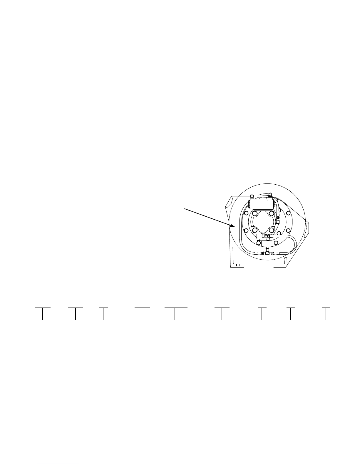
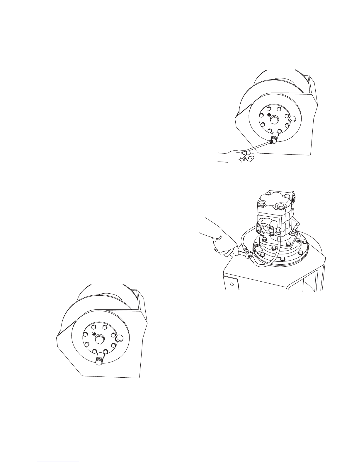
3. Vent Plug
The vent plug is located in the drum support as
shown. It is very important to keep this vent clean
and unobstructed. Whenever gear oil is changed,
remove vent plug, clean in solvent and reinstall.
Do not paint over the vent or replace with a solid
plug.
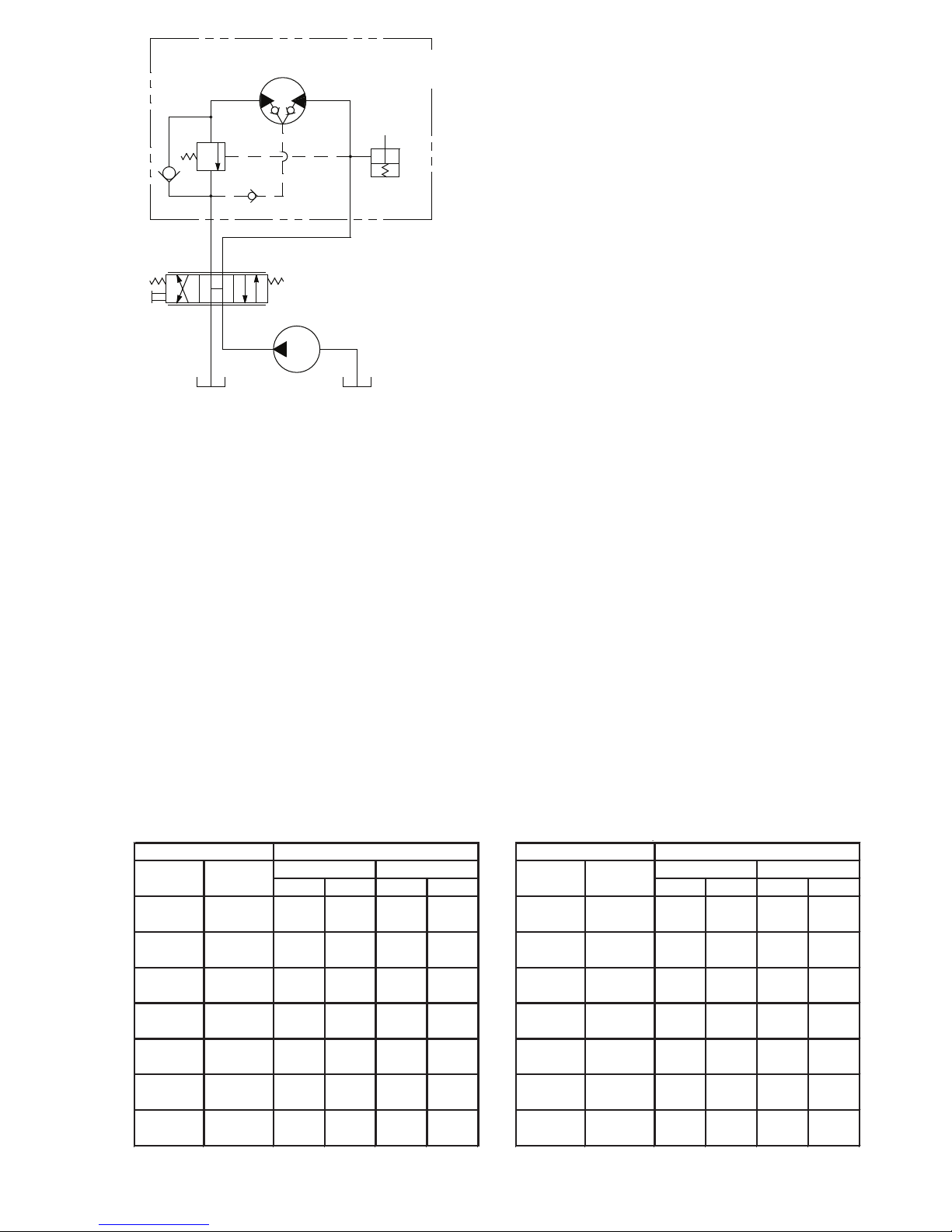
4. Hydraulic System
The original filter element should be replaced after
the first fifty (50) hours of operation, then every 500
operating hours or three (3) months, or in
accordance with the equipment manufacturer’s
recommendations.
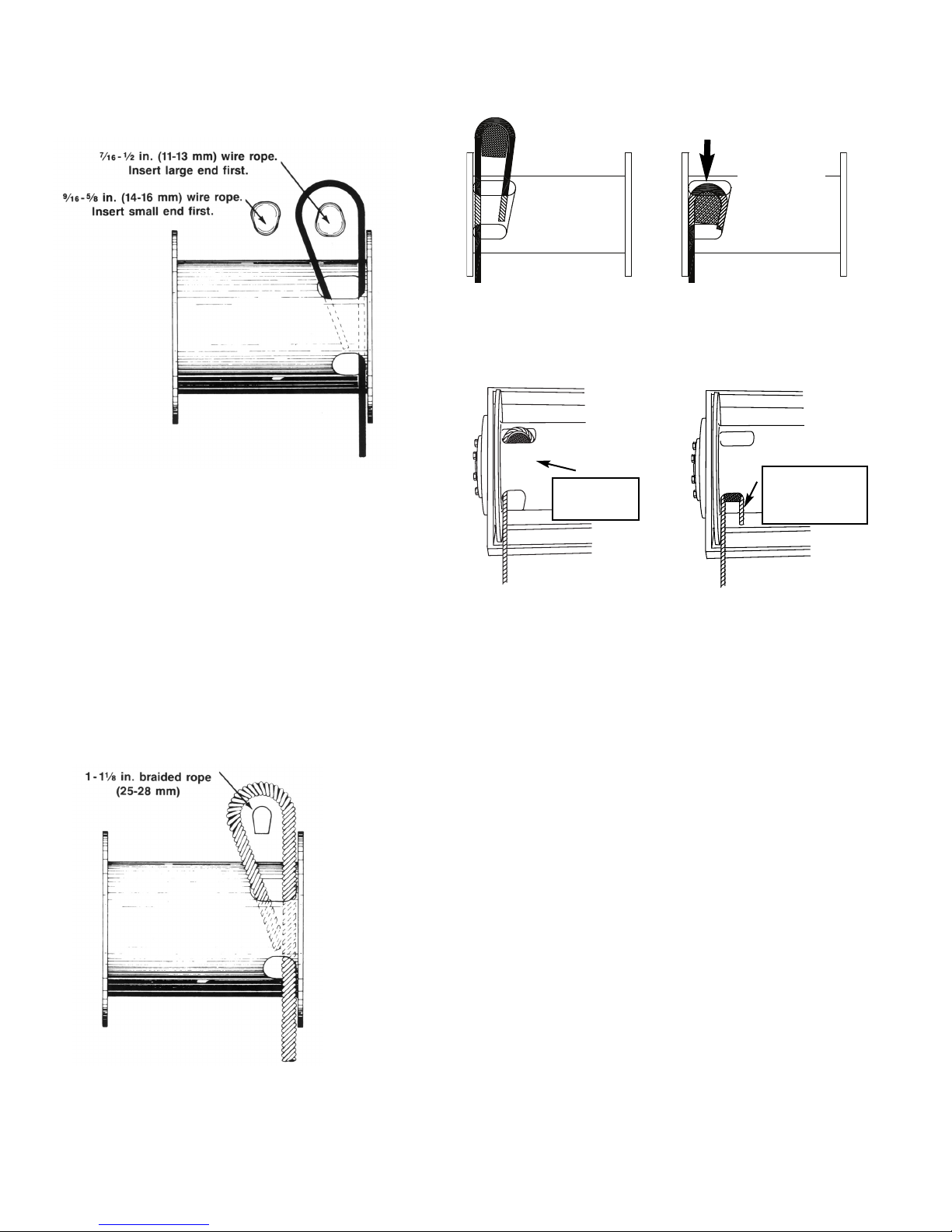
5. Wire Rope
Inspect entire length of wire rope according to wire
rope manufacturers recommendations.
6. Mounting Bolts
Tighten all winch base mounting bolts to
recommended torque after the first one hundred
(100) hours of operation, then every 1000 operating
hours or six (6) months, whichever occurs first.
7. Warm-up Procedures
Awarm-up procedure is recommended at each
start-up and is essential at ambient temperatures
below +40°F (4°C).
The prime mover should be run at its lowest
recommended RPM with the hydraulic winch
control valve in neutral allowing sufficient time to
warm up the system. The winch should then be
operated at low speeds, forward and reverse,
several times to prime all lines with warm hydraulic
oil, and to circulate gear lubricant through the
planetary gear sets.
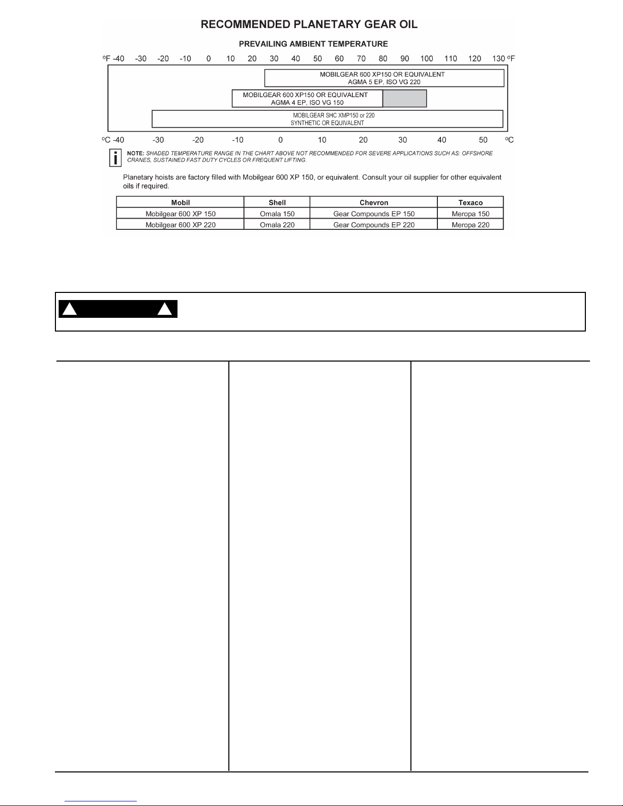
8. Recommended Planetary Gear Oil
Field experience, supported by extensive
engineering tests, indicates the use of the proper
planetary gear oil is essential to reliable and safe
operation of the brake clutch and obtaining long
gear train life.
For simplicity, BRADEN has listed one (1) readily
available product in each temperature range which
has been tested and found to meet our
specifications. This is not to say that other lubricant
brands would not perform equally as well.
If the following lubricant brands are not available in
your area, make certain your lubricant vendor
supplies you with oil that is equivalent to those
products listed below.
BRADEN planetary winches are factory filled with
Texaco Meropa 150 or equivalent AGMA No. 4EP
gear oil.
9. Inspection
In compliance with ANSI specification number
B30.5c1987 and API Recommended Practice RP
2D section 3, we recommend that the winch be
disassembled for a thorough inspection of all wear
items every 2,000 hours of operation or twelve (12)
months, whichever occurs first.
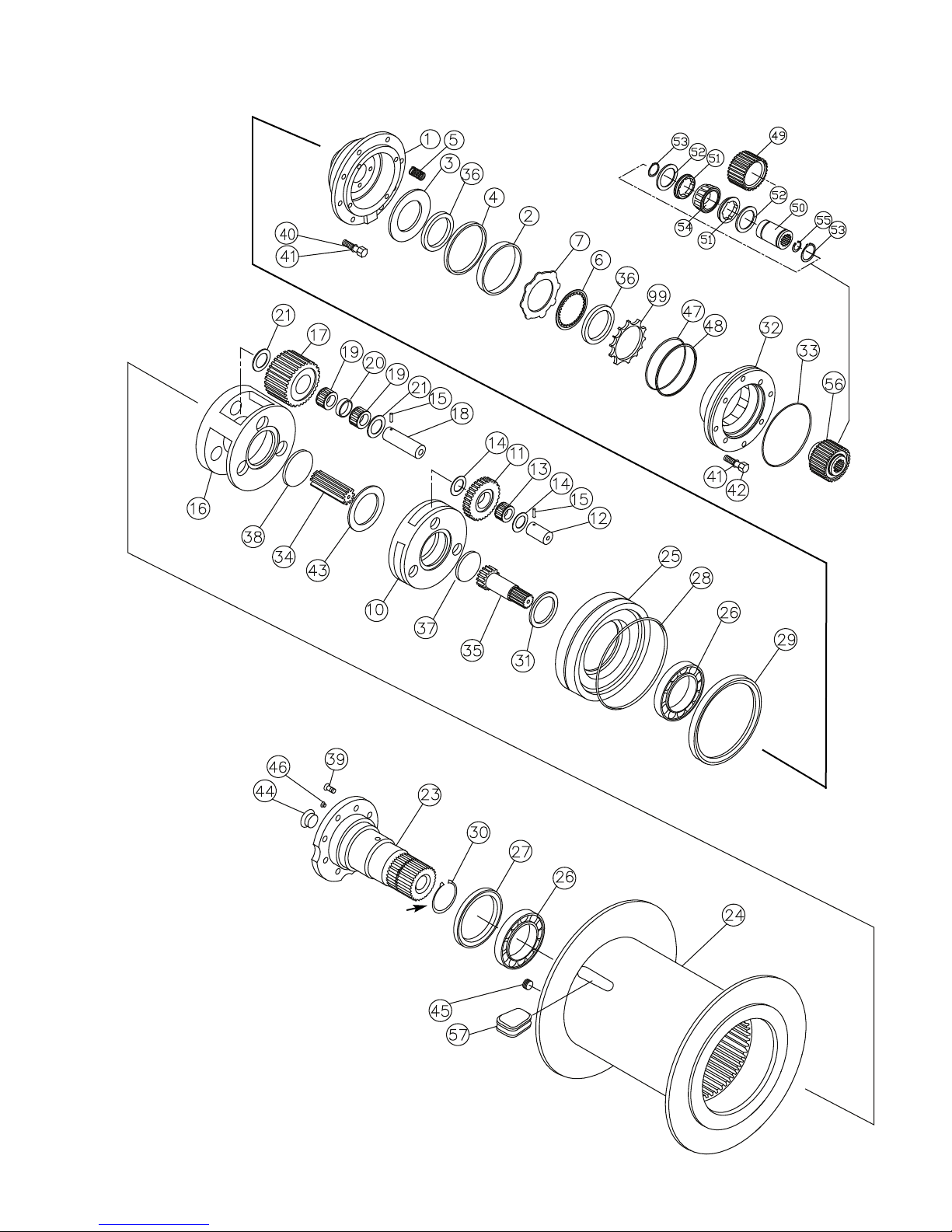
A. Bearings and Gears – Refer to
DISASSEMBLYOF WINCH, page 15; and
PLANET CARRIER SERVICE, page 20.
B. Brake Cylinder – Refer to MOTOR
SUPPORT– BRAKE CYLINDER SERVICE,
pages 22 and 23.
C. Brake Clutch – Refer to BRAKE CLUTCH
SERVICE, page 26.
Failure to properly warm up the winch, particularly
under low ambient temperature conditions, may
result in temporary brake slippage due to high back
pressures attempting to release the brake, which
could result in property damage, severe personal
injury or death.
Failure to use the proper type and viscosity of
planetary gear oil may contribute to intermittent brake
clutch slippage which could result in property
damage, severe personal injury or death. Some gear
lubricants contain large amounts of EP (extreme
pressure) and anti-friction additives which may
contribute to brake clutch slippage and damage to
brake friction discs or seals. Oil viscosity with regard
to ambient temperature is also critical to reliable
brake clutch operation. Our tests indicate that
excessively heavy or thick gear oil may contribute to
intermittent brake clutch slippage. Make certain that
the gear oil viscosity used in your winch is correct for
your prevailing ambient temperature.