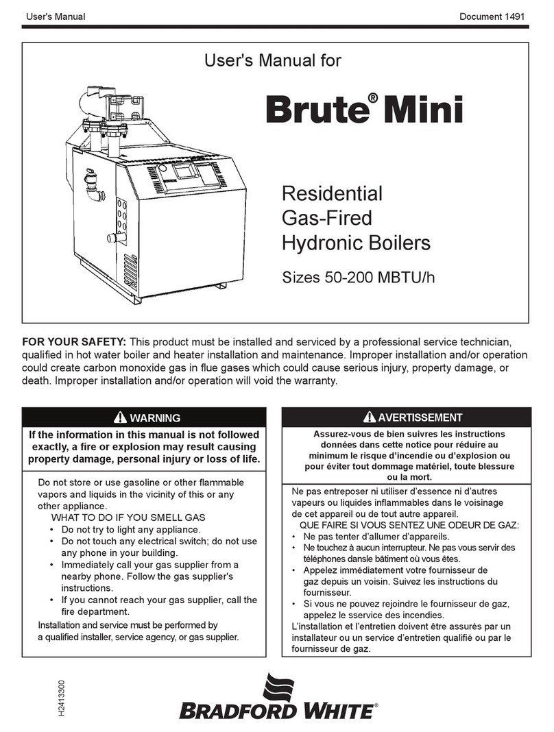
Bradford White Laars Pennant PNCH Series User manual
Other Bradford White Boiler manuals
Bradford White
Bradford White LAARS OmniTherm ONH1250 User manual

Bradford White
Bradford White Laars Linc MagnaTherm FT CFH1000 User manual

Bradford White
Bradford White BRHHH User manual
Bradford White
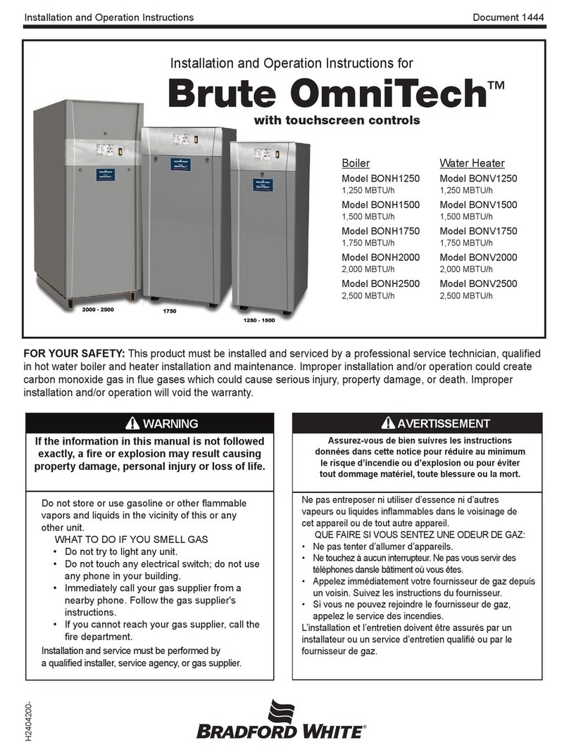
Bradford White Brute OmniTech BONV2500 Owner's manual

Bradford White
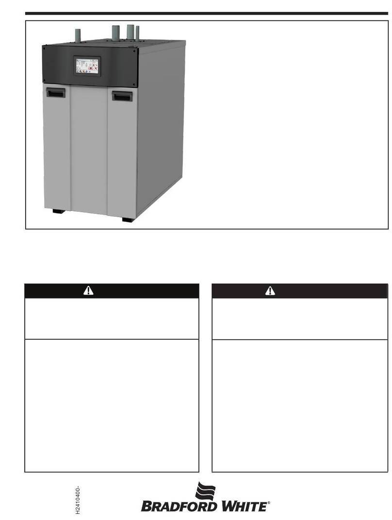
Bradford White BNTH1000 User manual
Bradford White
Bradford White Brute XTR Series User manual

Bradford White
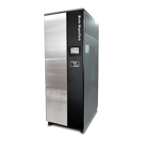
Bradford White Brute MagnaTech BMGH1600 User manual

Bradford White
Bradford White Brute XTR Series Owner's manual

Bradford White
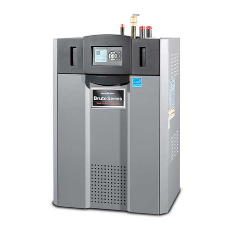
Bradford White FT Series Quick guide
Bradford White
Bradford White Brute BNTH User manual

Bradford White
Bradford White Laars NEOTHERM NTH Series Owner's manual

Bradford White
Bradford White FT Series Owner's manual

Bradford White
Bradford White Copper Brute II User manual
Bradford White
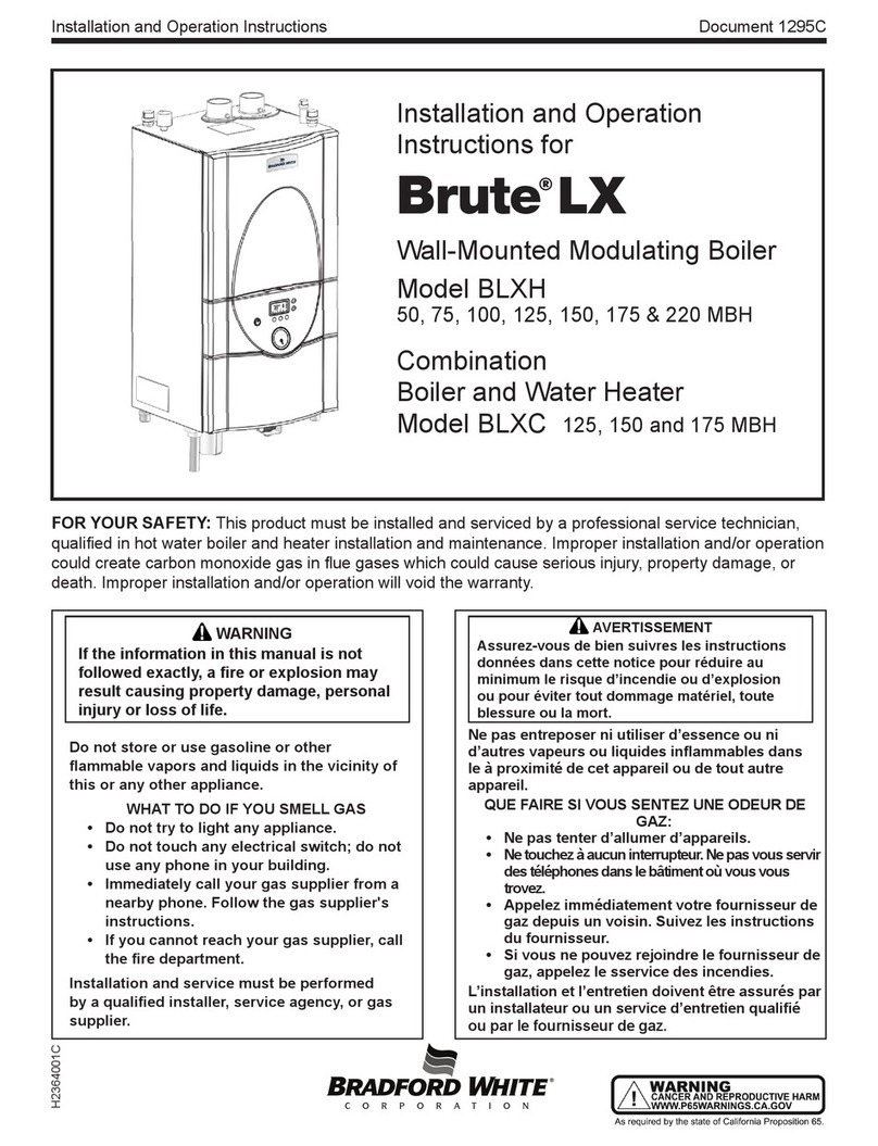
Bradford White Brute LX Owner's manual
Bradford White
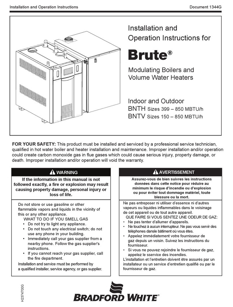
Bradford White Brute BNTH Series Owner's manual

Bradford White
Bradford White JVS User manual

Bradford White
Bradford White BRUTE DELUXE BMT2H User manual

Bradford White
Bradford White BWCH User manual

Bradford White
Bradford White Brute BNTH User manual

Bradford White
Bradford White Copper Brute II BWCH User manual
Popular Boiler manuals by other brands

Vaillant
Vaillant uniSTOR VIH SW GB 500 BES operating instructions

Radijator
Radijator BIO max 23.1 instruction manual

Brunner
Brunner BSV 20 Instructions for use

Buderus
Buderus Logamax GB062-24 KDE H V2 Service manual

Potterton
Potterton 50e Installation and Servicing Manual

UTICA BOILERS
UTICA BOILERS TriFire Assembly instructions

Joannes
Joannes LADY Series Installation and maintenance manual

ECR International
ECR International UB90-125 Installation, operation & maintenance manual

Froling
Froling P4 Pellet 8 - 105 installation instructions

Froling
Froling FHG Turbo 3000 operating instructions

U.S. Boiler Company
U.S. Boiler Company K2 operating instructions

Henrad
Henrad C95 FF user guide

NeOvo
NeOvo EcoNox EF 36 user guide

Potterton
Potterton PROMAX SL 12 user guide

Eco Hometec
Eco Hometec EC 25 COMPACT Technical manual

Viessmann
Viessmann VITODENS 200 Operating instructions and user's information manual

Baxi
Baxi Prime 1.24 installation manual

REXNOVA
REXNOVA ISA 20 BITHERMAL Installation, use and maintenance manual
