manuals.online logo
Brands
  1. Home
  2. •
  3. Brands
  4. •
  5. Bradford White
  6. •
  7. Heat Pump
  8. •
  9. Bradford White AeroTherm User manual

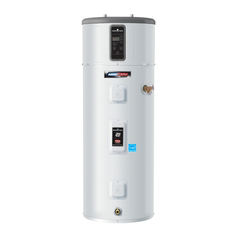
Bradford White AeroTherm User manual

4
Bradford White heat pump Care and cleaning.
If the water heater is to remain idle for an extended period of
time, the power and water to the appliance should be turned
off and the water heater drained to conserve energy and
prevent a buildup of dangerous hydrogen gas. This unit has
no power button, power can only be shut off at the circuit
breaker or disconnect switch.
If the water heater has an anode depletion sensing feature
(some models) and the water heater cannot be drained, it is
recommended to leave the power turned on with the water
heater in vacation mode to ensure that the feature will
continue to operate properly while still conserving energy.
The water heater and piping should be drained if they might
be subjected to freezing temperatures.
After a long shutdown period, the water heater’s operation
and controls should be checked by qualified service
personnel. Make certain the water heater is completely filled
again before placing it in operation.
NOTE: Refer to the Hydrogen Gas Caution in the Operating
Instructions (see page 3).
DRAINING THE WATER HEATER
CAUTION: Risk of Shock - Shut off power to
the water heater before draining water.
DANGER: Risk of Scald - Before manually
operating the relief valve, make certain no one will be exposed
to the hot water released by the valve. The water drained from
the tank may be hot enough to present a scald hazard and
should be directed to a suitable drain to prevent injury or
damage.
To drain the water heater, follow these steps:
1. Attach a garden hose to the drain valve located at the
bottom of the unit and direct that hose to a drain.
2. Turn o the cold water supply.
3. Admit air to the tank by opening a hot water faucet or
lifting the handle on the relief valve
4. Open the drain valve with a at screwdriver.
Note: See page 15 for product schematic.
EXTENDED SHUTDOWN PERIODS OR VACATIONS EXCEEDING VACATION MODE OPTIONS
Use a flat slot
screwdriver to
turn valve.
CLEARING THE CONDENSATION DRAIN TUBE
CLEANING THE FILTER
In the Hybrid, Heat Pump and High Demand/Boost modes, the heater
moves air through the system and out the back of the unit. The filter
is in place to protect the evaporator from dirt and dust.
A clean air filter is important to get the highest efficiency. Occasion-
ally this filter will need to be cleaned (minimum once per year). When
the filter requires cleaning, the Red light above the Filter button will be
illuminated and an audible beep will sound.
NOTE: If the filter gets too dirty, the unit will automatically switch to
Electric/Standard mode and energy savings will be lost.
Leave the power on. Remove the filter from
the top of the unit. Squeeze two tabs and lift to remove the air filter.
Once it has been removed, the filter can be vacuumed or wiped clean
with a damp cloth or rinsed with warm water.
Once the filter has been cleaned and dried, it can be replaced by
aligning it into the slots in the top of the unit and pushing it down into
place.
After the clean filter has been reinstalled, press and hold the FILTER
button. If a heating cycle is on when the filter fault is reset, it will con-
tinue in electric mode to finish the cycle. After that, it will automati-
cally revert to the mode it was in prior to being switched.
IMPORTANT: Filter must be cleaned when the alarm is displayed. A
dirty filter will make the system work harder and result in a reduction
of efficiency and possible damage to the system. In order to get the
best energy efficiency available, make sure your filter is clean.
The main drain is intended to carry all condensate away. If it is
clogged, the heat pump will stop operating, the display will show
F20, and an alarm will sound. Press any button to silence the
alarm, then clear the condensate drain by removing any drain
lines and connections, and clearing debris. Reattach drain lines
and connections, then allow the water heater to run.
Periodically inspect the drain lines and clear any debris that may
have collected in the lines.
See Installation
Instructions for
more information.
Main drain line
Direct the
main drain
tube into a
drain
Overow
Filter
Tabs
Slots
5
ANODE ROD
The anode rod should be removed from the water heater’s tank and
inspected once every 3 years service, and replaced when more than
6” (15.2 cm) of core wire is exposed at either end of the rod. For more
information contact us at www.bradfordwhite.com.
NOTE: Artificially softened water requires that the anode rod be
inspected annually.
Due to shock hazard and to prevent accidental water leaks, this
inspection should be done by a qualified servicer or plumber, and
requires that the electric power and cold water supply be turned off
before servicing the anode rod.
NOTICE: Do not remove the anode rod from the water heater’s tank
except for inspection and/or replacement, as operation with the
anode rod removed will shorten the life of the glass-lined tank and
will void warranty coverage.
The anode rod consumption and replacement are not covered by
warranty.
Some areas have water conditions that may cause an odor to
develop in the water heater. Aluminum-Zinc alloy replacement rods
are available to address the condition.
Additional information for products with an anode depletion
sensing feature:
When the system indicates that the anode depletion sensing anode
rod is approaching end of life, it is recommended to replace it. To
silence the alarm, press the Anode button once. Call Bradford White
Tech Service to order or to replace the anode depletion sensing
anode rod. After replacing, reset the Anode alarm by pressing and
holding the Anode button for 10 seconds until the control beeps and
the LED above the button turns off.
If an Aluminum-Zinc anode rod is installed to address a water odor
condition, the anode depletion sensing feature must be disabled.
Upon power-up after installing an Aluminum-Zinc anode rod, the
control will sound an alarm. To quiet the alarm and disable the
feature, first press the Anode button once to silence the alarm, then
press the Anode button 3 times. The control will beep and a message
will scroll on the display confirming that the feature has been
disabled. Annual inspections of the anode rod are recommended
since the water heater will no longer be capable of alerting for a
depleted anode rod. To enable the feature if an anode depletion
sensing anode rod is installed, press the Anode button 3 times. The
control will beep and a message will scroll on the display confirming
that the feature has been enabled.
NOTE: If the water heater has been installed with a device that
periodically cuts power to the water heater, the accuracy of the
anode rod depletion sensing feature may become compromised and
anode rod inspection every 2-3 years is recommended.
If the water heater will be inactive for a long period of time and the
water heater cannot be drained, it is recommended to leave the
power turned on with the water heater in vacation mode to ensure
that the feature will continue to operate properly while still conserving
energy.
NOTE: Refer to the Hydrogen Gas Caution in the Operating
Instructions (see page 1).
Tools needed:
• T20 Torx Screwdriver • Socket Extention 12” long
• Slot Screwdriver • 1-1/16” Socket
• Tape • Socket Wrench
• Softset Sealant • Anode Rod, if needed
To service the Anode Rod:
1. Disconnect power, shut off the water supply, and partially drain
one or two gallons from the water heater through the lower
drain valve.
2. Remove the filter, trim ring,
and front top cover as
show in Illustration A.
3. Reinstall the trim ring,
place a protective layer
of tape on sheet metal
edges, as show in
Illustration B.
4. Remove insulation to
uncover the anode rod
as show in Illustration
B. Unplug anode wire (on
some models).
5. Using a 1-1/16”
socket and
extension,
unscrew the
anode rod, then
lift out to inspect
as show in
Illustration C.
6. To install the
anode rod, seal
the threads with
soft set sealant,
thread into the port
and using the torque
wrench tighten to
50 ± 5 ft-lbs of
torque. Plug in the
wire for the anode
rod if present.
Reinstall the anode
rod insulation. If an
Aluminum-Zinc or
other non-sensing
anode rod is
installed, the anode depletion sensing feature must be disabled
and the wire end taped (some models).
7. Turn water supply on, open a tap to remove any air in
plumbing system, inspect for leaks, then reassemble the unit
in reverse order as shown in Illustration A, and turn the power
on. Reset the Anode button (some models) by pressing and
holding for 10 seconds to indicate that a new anode depletion
sensing anode rod is installed.
Anode Rod Maintenance and Service.
This information is intended to use by individuals possessing adequate background of electrical, electronic and mechanical expe-
rience. Any attempt to repair a major appliance may result in personal injury and property damage. The manufacturer or seller
cannot be responsible for the interpretation of this information, nor can it assume any liability in connection with its use.
TITLE
Filter
Trim Ring
Front
Top Cover
Illustration A
Trim Ring
Tape Process
Tube Pinch O
Anode Rod
Insulation Foam
Tape Corner
and Edges
Wires
Wires
Illustration B
Anode Rod
Illustration C
CAUTION - IMPORTANT SAFETY NOTICE

Other Bradford White Heat Pump manuals

Bradford White RE2H50 User manual

Bradford White

Bradford White RE2H50 User manual

Bradford White RE2H50S*-1NCWT Series User manual

Bradford White

Bradford White RE2H50S*-1NCWT Series User manual

Bradford White RE2H65T 1NCWT Series User manual

Bradford White

Bradford White RE2H65T 1NCWT Series User manual

Popular Heat Pump manuals by other brands

IV Produkt EcoHeater 060-1 Operation and maintenance instructions

IV Produkt

IV Produkt EcoHeater 060-1 Operation and maintenance instructions

Nordyne T5BP Series User's manual & installation instructions

Nordyne

Nordyne T5BP Series User's manual & installation instructions

EAS Electric M-THERMAL 2 R32 BIBLOCK instruction manual

EAS Electric

EAS Electric M-THERMAL 2 R32 BIBLOCK instruction manual

LG MULTI V B1 Series installation manual

LG

LG MULTI V B1 Series installation manual

CTC Union EcoPart 600M Installation and Maintenance

CTC Union

CTC Union EcoPart 600M Installation and Maintenance

Kaysun KHHP-BI Owners and installation manual

Kaysun

Kaysun KHHP-BI Owners and installation manual

ANTEK AIR MAGNA 100 Installation and maintenance instructions

ANTEK

ANTEK AIR MAGNA 100 Installation and maintenance instructions

Panasonic WH-MDC05H3E5 Service manual

Panasonic

Panasonic WH-MDC05H3E5 Service manual

STIEBEL ELTRON WWK 300 electronic SOL Operation and installation manual

STIEBEL ELTRON

STIEBEL ELTRON WWK 300 electronic SOL Operation and installation manual

Daikin EKHH2E-AV3 Installation and user manual

Daikin

Daikin EKHH2E-AV3 Installation and user manual

Lennox SunSource brochure

Lennox

Lennox SunSource brochure

Mitsubishi Electric PKA-A18HA6 Service manual

Mitsubishi Electric

Mitsubishi Electric PKA-A18HA6 Service manual

Trianco Activair Installation, operation and service manual

Trianco

Trianco Activair Installation, operation and service manual

Detandt-Simon BATHERM A Series Operation and installation manual

Detandt-Simon

Detandt-Simon BATHERM A Series Operation and installation manual

DeDietrich ALEZIO S V200 user guide

DeDietrich

DeDietrich ALEZIO S V200 user guide

CLIMAVENETA AWR MTD Service manual

CLIMAVENETA

CLIMAVENETA AWR MTD Service manual

Dimplex LA 11MAS Installation and operating instructions

Dimplex

Dimplex LA 11MAS Installation and operating instructions

Danfoss DHP-H Varius Pro+ Installation quick guide

Danfoss

Danfoss DHP-H Varius Pro+ Installation quick guide

manuals.online logo
manuals.online logoBrands
  • About & Mission
  • Contact us
  • Privacy Policy
  • Terms and Conditions

Copyright 2025 Manuals.Online. All Rights Reserved.