Braebon Ultima 0580A User manual

8OWLPD'XDO$LUIORZ
3UHVVXUH6HQVRU.LW
0RGHO$'
8VHU*XLGH
Pour une traduction française de ce guide
d'utilisateur, allez à www.braebon.com
Per una traduzione italiana di questa
guida dell'utente, vada a
www.braebon.com
Für eine deutsche Übersetzung dieses
Benutzerführers, gehen Sie zu
www.braebon.com
Para una traducción española de esta
guía del usuario, vaya a
www.braebon.com
$
%UDHERQ0HGLFDO&RUSRUDWLRQ
3URGXFW

7DEOHRI&RQWHQWV
7DEOHRI&RQWHQWV
,QWHQGHG8VH
6DIHW\,QIRUPDWLRQ
6DIHW\&RQYHQWLRQV
:DUQLQ V
&DXWLRQV
)HDWXUHVRIWKH8OWLPD'XDO$LUIORZ3UHVVXUH6HQVRU
'XDO$LUIORZ3UHVVXUH6HQVRU.LW$'&RQWHQWV
$ERXWWKH8OWLPD'XDO$LUIORZ3UHVVXUH6HQVRU
,QSXWV
2XWSXWV
*DLQDQG%DVHOLQH$GMXVWPHQW6FUHZV
%DWWHU\6WDWXV,QGLFDWRU/('
&RQQHFWLQ WKH8OWLPD'XDO$LUIORZ3UHVVXUH6HQVRU
STEP 1: &RQQHFWWKHSUHVVXUHVHQVRUWR\RXUVOHHSUHFRUGLQ V\VWHP
STEP 2: &RQQHFWWKHVDIHW\ILOWHURQWKHFDQQXODWRWKHSUHVVXUHVHQVRULQSXWV
STEP 3: 3RVLWLRQWKHFDQQXODRQWKHSDWLHQW
STEP 4: $GMXVWWKH DLQLIQHFHVVDU\
&DOLEUDWLQ WKH8OWLPD'XDO$LUIORZ3UHVVXUH6HQVRU
0DLQWDLQLQ WKH8OWLPD'XDO$LUIORZ3UHVVXUH6HQVRU
5HSODFLQ WKH%DWWHU\
7URXEOHVKRRWLQ
3URGXFW6SHFLILFDWLRQV
:DUUDQW\

,QWHQGHG8VH
QWHQGHG8VH
The Ultima Dual Airflow Pressure Sensor™ is intended for use during sleep disorder studies as a
measure of respiratory airflow for recording onto a data acquisition system.
The Ultima Dual Airflow Pressure Sensor™ is a battery-powered pressure transducer that uses
state-of-the-art-miniaturized technology to detect and reproduce waveforms associated with
respiratory airflow from both the nose and mouth. Respiratory pressures are converted into
voltage signals compatible with a variety of data acquisition systems.
The differential pressure system uses either custom Braebon™ cannulas (Model 0589, 0588,
0582s, or others) or standard oxygen (O2) cannulas with the Braebon™ safety filter. The single-
use nasal cannula has a 0.2-micron hydrophobic filter that prevents the spread of contaminants
between patients and prevents moisture damage to the pressure sensor. The cannula attaches to
the positive input of the Ultima Dual Airflow Pressure Sensor™.
The pressure sensor essentially functions as an uncalibrated pneumotachograph. The sensor
detects and amplifies pressure swings from the cannula using a stable pressure transducer
capable of detecting differential pressures in the ±25 cm H2O range. The corresponding voltage is
then output for data acquisition.
6DIHW\,QIRUPDWLRQ
6DIHW\ QIRUPDWLRQ
For your personal safety, please read the safety conventions and the warnings and cautions in this
manual.
6DIHW\&RQYHQWLRQV
These are the safety conventions for this manual. The table below lists the safety symbol, the
name for the symbol, and the meaning of the symbol.
Warning
The Warning message appears in the manual before
procedures or tasks that must be strictly observed to avoid
patient injury or harm.
Caution
The Caution message appears in the manual before
procedures or tasks that must be strictly observed to avoid
damage to the product.
Note The Note message contains important information to help
the operator complete a procedure or task correctly.
6DIHW\,QIRUPDWLRQ
• The Ultima Dual Airflow Pressure Sensor™ is for diagnostic use only; it is NOT intended as an
apnea monitor, and it is NOT to be used in life sustaining situations.
• U.S. Federal law restricts this device to sale by or on the order of a physician.
• Always use a new single-use Ultima Airflow Pressure Cannula (Model 0589, 0588, 0582s, or
others) and a new Braebon™ safety filter (Model 0583) with each patient. The Braebon™
safety filter is required to prevent the spread of contaminants between patients and to prevent
moisture damage to the pressure sensor. Failure to use the Braebon™ safety filter will void the
warranty.
• To prevent dust contamination to the pressure sensor always keep safety filters attached to
the unit and change the safety filters immediately prior to next patient use.
• Use only isopropyl alcohol pads to clean the pressure sensor.
•DoNOT immerse the pressure sensor (Model 0585) in any liquids.
•DoNOT steam autoclave or gas sterilize the pressure sensor or damage will result.
• Use two 1.5V AA batteries or damage to the Ultima Dual Airflow Pressure Sensor™ will result.
Do NOT mix battery types. Do NOT insert the batteries backwards.
• If mounting the pressure sensor on the wall, mount the unit upside down to minimize the
likelihood of bending or kinking the cannula tubing.
:DUQLQJV
&DXWLRQV
)HDWXUHVRIWKH8OWLPD'XDO$LUIORZ3UHVVXUH6HQVRU
)HDWXUHVRIWKH8OWLPD'XDO$LUIORZ
3UHVVXUH6HQVRU
• Six Outputs
• Three Inputs
• Gain and Baseline Adjustment
•ON/OFFSwitch Auto-Off (after 10 hours run-time)
• Battery Powered 2 AA Alkaline Batteries
• Nasal Airflow &
Snoring Output
Pure or raw nasal airflow pressure with superimposed snoring
signal
• Nasal Airflow Output Filtered nasal airflow pressure with no snoring signal
• Nasal Snoring
Output
Snoring signal from upper airway pressure vibrations
• Oral Airflow &
Snoring Output
Pure or raw oral airflow pressure with superimposed snoring
signal
• Oral Airflow Output Filtered oral airflow pressure with no snoring signal
• Oral Snoring Output Snoring signal from upper airway pressure vibrations
• Nasal Input Facilitates combining nasal and oral breathing on one channel
by connecting a Braebon™ Ultima Oral/Nasal Cannula (Model
0589) to the nasal input only
Facilitates recording nasal breathing only using any nasal
cannula with a Braebon™ Safety Filter (Model 0583) connected
to the nasal input only
• Differential Nasal
Input
Facilitates connection to a CPAP circuit
• Oral Input Facilitates recording nasal and oral breathing on separate
channels by connecting a Braebon™ Ultima Oral & Nasal Dual
Lumen Cannula (Model 0588) to both the oral and nasal inputs
• Battery Status
Indicator LED
Blinks green every 10 seconds to indicate the batteries are OK
Blinks red every two seconds to indicate the batteries are low

'XDO$LUIORZ3UHVVXUH6HQVRU.LW$'&RQWHQWV
'XDO$LUIORZ3UHVVXUH6HQVRU.LW
$'&RQWHQWV
The 0580A and 0580D Dual Airflow Pressure Sensor kits include the following items:
• One Ultima Dual Airflow Pressure Sensor™ (Model 0585)
• One adult dual lumen nasal & oral cannula with hydrophobic filter (Model 0588)
• One adult nasal/oral cannula with hydrophobic filter (Model 0589)
• Two adult nasal micro cannulas with hydrophobic filter (Model 0582s)
• One AC Interface Cable (Model 0592)
• One DC Interface Cable (Model 0594)
• Two 1.5 volt AA alkaline batteries (installed when shipped from the factory)
• One User Guide
In addition to the items mentioned above, the 0580A Dual Airflow Pressure Sensor Kit for Alice
includes the following:
• Two Alice Interfaces for the 0585 Dual Pressure Sensor (Model 0586A)
• Two Alice Interface Cables (Model 0593)
$ERXWWKH8OWLPD'XDO$LUIORZ3UHVVXUH6HQVRU
$ERXWWKH8OWLPD'XDO$LUIORZ
3UHVVXUH6HQVRU
The Ultima Dual Airflow Pressure Sensor™ is a differential pressure transducer that detects and
amplifies pressure swings in the cm of H2O range. The voltage corresponding to the
differential pressure is output for data acquisition.
The Ultima Dual Airflow Pressure Sensor™ has three inputs and six outputs with an output range
of volts. With the Ultima Dual Airflow Pressure Sensor™, you can adjust the gain and baseline
controls for both the nasal and oral output channels. The output range will vary according to the
gain and baseline settings you used during recording.
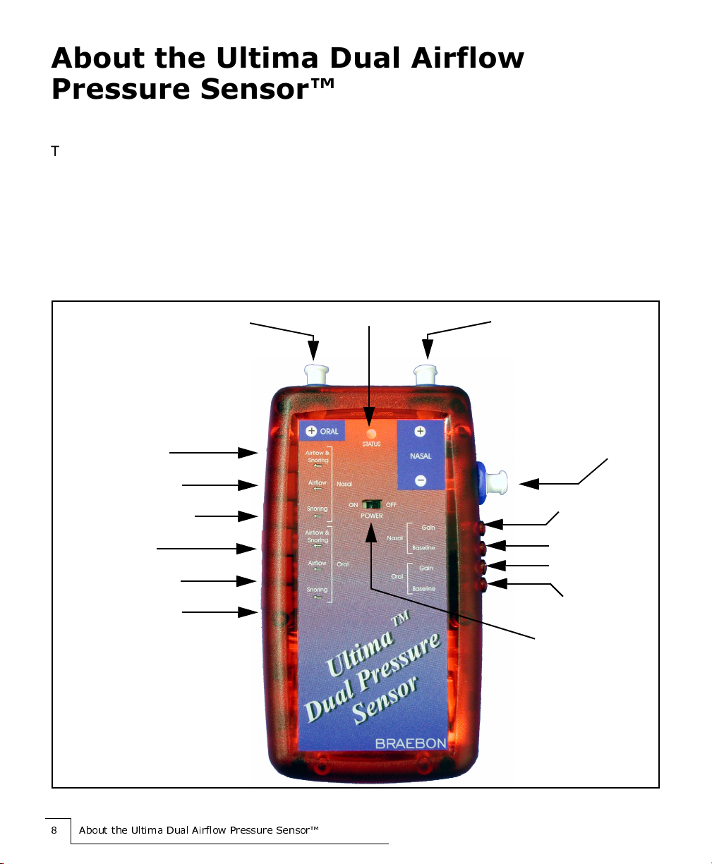
Figure 1 The Ultima Dual Airflow Pressure Sensor™
25
±
5±
Nasal Cannula Input
Oral Cannula Input
Nasal
Differential
Input (CPAP
connection)
Battery Status Indicator LED
ON/OFF Switch
Nasal Airflow &
Snoring Output
Nasal Airflow Output
Nasal Snoring Output
Oral Airflow &
Snoring Output
Oral Airflow Output
Oral Snoring Output
Nasal Gain
Nasal Baseline
Oral Gain
Oral Baseline

$ERXWWKH8OWLPD'XDO$LUIORZ3UHVVXUH6HQVRU
QSXWV
The Ultima Dual Airflow Pressure Sensor™ has three inputs: nasal input, nasal differential input
(CPAP connection), and oral input.
Nasal Input
With the nasal input, you can either combine oral and nasal breathing into one channel using
a single lumen, oral/nasal cannula connected to the nasal input or you can record nasal
breathing only using any nasal cannula connected to the nasal input.
Nasal Differential Input
With the nasal differential input, you can subtract a known pressure from the nasal baseline by
connecting your CPAP circuit to the nasal differential input.
The nasal differential input is your baseline for the nasal input. If you do not connect anything,
then you are using atmospheric pressure as your baseline for your nasal input. However, if
you attach a CPAP circuit to the nasal differential input, then you are using the CPAP pressure
as the baseline instead of atmospheric pressure.
Oral Input
With the oral input, you can record oral and nasal breathing on separate channels using a
dual lumen, oral and nasal cannula connected to both the oral and nasal input.

$ERXWWKH8OWLPD'XDO$LUIORZ3UHVVXUH6HQVRU
2XWSXWV
On the left side of the Ultima Dual Airflow Pressure Sensor™, there are six outputs — three nasal
outputs and three oral outputs. See Table 1 Output Types. You may choose to record from one to
six outputs from the Ultima Dual Airflow Pressure Sensor™.
Table 1 Output Types
Output Name Signal Type Example of Signal
• Nasal Airflow
& Snoring
Output
Pure or raw nasal airflow pressure with
superimposed snoring signal
• Nasal Airflow
Output
Filtered nasal airflow pressure with no
snoring signal
• Nasal Snoring
Output
Snoring signal from upper airway
pressure vibrations
• Oral Airflow &
Snoring
Output
Pure or raw oral airflow pressure with
superimposed snoring signal
•OralAirflow
Output
Filtered oral airflow pressure with no
snoring signal
• Oral Snoring
Output
Snoring signal from upper airway
pressure vibrations
Nasal Airflow and Snoring (Unfiltered)
Nasal Airflow (Snoring Filtered Out)
Nasal Snoring (Airflow Filtered Out)
Oral Airflow and Snoring (Unfiltered)
Oral Airflow (Snoring Filtered Out)
Oral Snoring (Airflow Filtered Out)
$ERXWWKH8OWLPD'XDO$LUIORZ3UHVVXUH6HQVRU
*DLQDQG%DVHOLQH$GMXVWPHQW6FUHZV
On the right side of the Ultima Dual Airflow Pressure Sensor™, there are four, 20-turn screws that
allow you to adjust both the gain and baseline settings for both the nasal and oral outputs. The
baseline is set to zero volts in our factory. Under most circumstances, however, you will NOT need
to make adjustments.
Gain adjustment screws
There are two gain adjustments screws: a nasal gain screw and an oral gain screw. The nasal
gain screw allows you to adjust the gain for all the nasal outputs. Similarly, you can adjust the
gain for all the oral outputs with the oral gain screw.
By adjusting the gain or sensitivity, you enlarge or reduce the size of the waveform on the
display of your recording system. You do not change the actual recorded signal.
By turning the gain screw clockwise, you increase the sensitivity to make the signal larger. By
turning the gain screw counterclockwise, you decrease the sensitivity to make the signal
smaller.
Baseline adjustment screws
The baseline is set to zero volts in our factory. Under most circumstances, however, you
will NOT need to make adjustments.
If you do want to make adjustments, there are two baseline adjustments screws: a nasal
baseline screw and an oral baseline screw. The nasal baseline screw allows you to adjust
the baseline for all the nasal outputs. Similarly, you can adjust the baseline for all the oral
outputs with the oral baseline screw.
When you turn the baseline adjustment screw, you change the position of the waveform
on the display of your recording system. You move the waveform further up or further
down on the display so you can view the signal peak-to-peak. The baseline is set to zero
volts in the factory.
By turning the baseline screw clockwise, you move the baseline higher; that is, increase
the baseline voltage. By turning the baseline screw counterclockwise, you move the
baseline lower; that is, decrease the baseline voltage.
Caution: Do NOT adjust the baseline without a voltmeter.

$ERXWWKH8OWLPD'XDO$LUIORZ3UHVVXUH6HQVRU
%DWWHU\6WDWXV QGLFDWRU/('
Centred on the face of the Ultima Dual Airflow Pressure Sensor™, there is a Battery Status
Indicator LED. The LED flashes either green or red to indicate the status of the batteries in the
Ultima Dual Airflow Pressure Sensor™. See Table 2 Battery Status.
Usually, the batteries will last about 30 - 50 nights (8-hour recordings) depending on the battery
type used. When the Battery Status Indicator LED blinks red, replace your batteries with new AA
alkaline batteries. See the Troubleshooting section, if the LED is not blinking.
Table 2 Battery Status
LED Color Period Status
One Green Blink, One Red Blink At Start-up Only Pressure Sensor is ON
GREEN Every 10-15 Seconds Battery OK
RED Every 2 Seconds Battery LOW
&RQQHFWLQJWKH8OWLPD'XDO$LUIORZ3UHVVXUH6HQVRU
&RQQHFWLQJWKH8OWLPD'XDO$LUIORZ
3UHVVXUH6HQVRU
Connecting the Ultima Dual Airflow Pressure Sensor™ to your sleep system and to the patient
consists of four steps:
STEP 1:Connect the pressure sensor to your sleep recording system.
STEP 2:Connect the safety filter on the cannula to the pressure sensor inputs.
STEP 3:Position the cannula on the patient.
STEP 4:Adjust the gain, if necessary.
67(3 &RQQHFWWKHSUHVVXUHVHQVRUWR\RXU
VOHHSUHFRUGLQ V\VWHP
The connection set-up and recorder settings for the pressure sensor depend upon the sleep
recording system you are using:
Warning: Always use a new single-use Ultima Airflow Pressure Cannula
(Model 0589, 0588, 0582s, or others) and a new safety filter (Model 0583) with
each patient. The safety filter is required to prevent the spread of contaminants
between patients and to prevent moisture damage to the pressure sensor.
Caution: To prevent dust contamination to the Ultima Dual Airflow Pressure
Sensor™, keep safety filters attached to the unit at all times and change the
safety filters immediately prior to patient use.
• AC Amplifier See “To connect to an AC amplifier” on page 14.
• DC Amplifier, DC Input, or
Multiplexer connection
See “To connect to a DC amplifier, DC Input, or
Multiplexer connection” on page 15.
• Alicea
D $OLFHLVDUHJLVWHUHGWUDGHPDUNRI5HVSLURQLFV,QF
See "To connect to Alice (Respironics)" on page 16.
&RQQHFWLQJWKH8OWLPD'XDO$LUIORZ3UHVVXUH6HQVRU
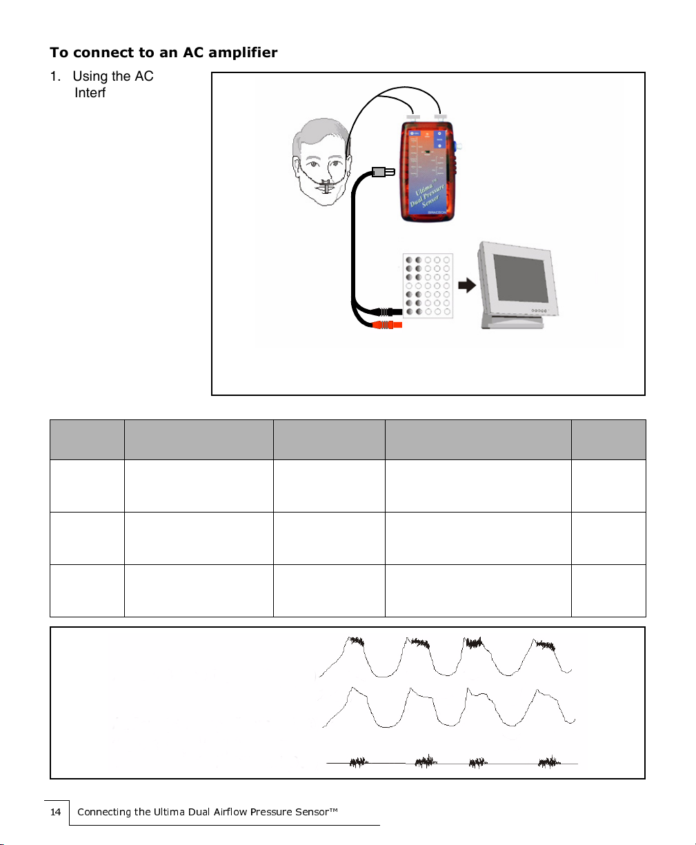
7RFRQQHFWWRDQ$&DPSOLILHU
1. Using the AC
Interface cable
(Model 0592),
connect a 1 mm
keyhole connector to
each of the outputs
you would like to
record. You may
record from one to
six outputs.
2. Connect the 1.5 mm
safety pin
connectors to your
headbox.
3. Use the Braebon™
recommended AC
recorder settings
listed in Table 3 AC
Recorder Settings.
Table 3 AC Recorder Settings
Channel
Output
Low Frequency Filter
(time constant)
High Frequency
Filter Gain/Sensitivity Sampling
Rate
Airflow &
Snoring
Output
0.05 Hz or lower
(3 seconds or longer)
70 Hz or higher 20 mV/cm or
1000 x increase or decrease as
necessary
100 Hz or
greater
Airflow
Output
0.05 Hz or lower
(3 seconds or longer)
10 Hz or higher 20 mV/cm or
1000 x increase or decrease as
necessary
20 Hz or
greater
Snoring
Output
10 Hz or lower
(0.16 seconds or longer)
70 Hz or higher 20 mV/cm or
1000 x increase or decrease as
necessary
100 Hz or
greater
Dual Pressure Sensor (0585)
AC Headbox Recording System
Note: You can connect
one to six cables from
the output of the
pressure sensor to the
input of the AC
headbox
Dual lumen, oral and nasal
cannula connected to both the
nasal and oral input
Figure 2 Complete AC Recorder Connection
Airflow and Snoring (Unfiltered)
Airflow (Snoring Filtered Out)
Snoring (Airflow Filtered Out)

&RQQHFWLQJWKH8OWLPD'XDO$LUIORZ3UHVVXUH6HQVRU
7RFRQQHFWWRD'&DPSOLILHU'& QSXWRU0XOWLSOH[HUFRQQHFWLRQ
1. Using the DC
Interface cable
(Model 0594),
connect a 1 mm
keyhole connector to
each of the outputs
you would like to
record. You may
choose to record
from one to six
outputs.
2. Connect the 1/8 inch
female stereo
connector to your
DC amplifier.
3. Use the DC recorder
settings listed in
Table 4 DC Recorder
Settings.
Table 4 DC Recorder Settings
Channel
Output
Low Frequency Filter
(time constant) High Frequency Filter Gain/Sensitivity Sampling
Rate
Airflow &
Snoring
Output
N/A 70 Hz or higher 20 mV/cm or
1000 x increase or
decrease as necessary
100 Hz or
greater
Airflow
Output
N/A 10 Hz or higher 20 mV/cm or
1000 x increase or
decrease as necessary
20 Hz or
greater
Snoring
Output
N/A 70 Hz or higher 20 mV/cm or
1000 x increase or
decrease as necessary
100 Hz or
greater
Dual Pressure Sensor (0585)
DC Headbox Recording System
Note: You can connect
one to six cables from
the output of the
pressure sensor to the
input of the DC
headbox
Dual lumen, oral and nasal cannula
connected to both the nasal and oral
input
Figure 3 Complete DC Recorder Connection
Airflow and Snoring ( Unfiltered)
Airflow (Snoring Filtered Out)
Snoring (Airflow Filtered Out)
&RQQHFWLQJWKH8OWLPD'XDO$LUIORZ3UHVVXUH6HQVRU
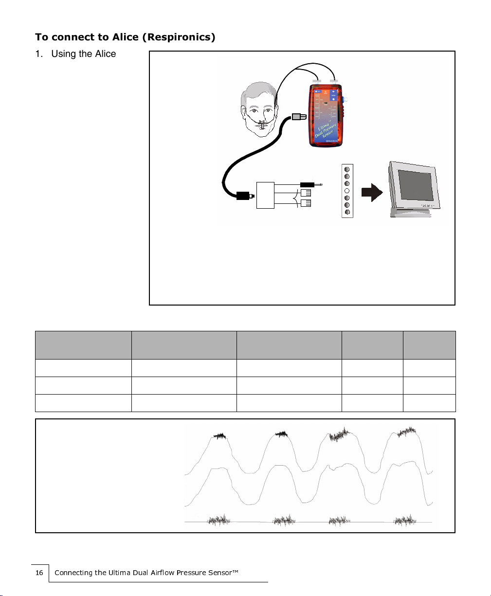
7RFRQQHFWWR$OLFH5HVSLURQLFV
1. Using the Alice
Interface cable
(Model 0593),
connect a 1 mm
keyhole connector to
each of the outputs
you would like to
record. You may
choose to record
from one to six
outputs.
2. Connect the RCA
connector to the
0586A interface.
3. Plug the RJ11
connectors into your
Alice DC box.
4. Use the recorder
settings listed in
Table 5 Alice
Recorder Settings.
Table 5 Alice Recorder Settings
Channel Output Low Frequency Filter
(time constant) High Frequency Filter Gain/
Sensitivity
Sampling
Rate
Airflow & Snoring Output N/A 70 Hz or higher 7 N/A
Airflow Output N/A 10 Hz or higher 7 N/A
Snoring Output N/A 70 Hz or higher 7 N/A
Dual Pressure Sensor (0585)
Alice DC
box
Recording
System
Note: You
can use
one to six
outputs
on the
pressure
sensor.
Dual lumen, oral and nasal
cannula connected to both
the nasal and oral input
Figure 4 Complete Alice Recorder Connection
0586A
PFS
RJ11
3/32 inch stereo
On the 0586A interface
P= Pure waveform with both airflow &
snoring (Unfiltered)
F= Filtered waveform with airflow only
S= Snoring only
Airflow and Snoring ( Unfiltered)
Airflow (Snoring Filtered Out)
Snoring (Airflow Filtered Out)

&RQQHFWLQJWKH8OWLPD'XDO$LUIORZ3UHVVXUH6HQVRU
67(3 &RQQHFWWKHVDIHW\ILOWHURQWKH
FDQQXODWRWKHSUHVVXUHVHQVRULQSXWV
The inputs you use on the pressure sensor depend upon whether you plan to record nasal and
oral breathing on separate channels or on a single channel, record nasal breathing only, or
perform a CPAP titration study in which you subtract a known pressure from the nasal baseline.
• Record nasal and oral
breathing on separate
channels
Using a Braebon™ Ultima Oral & Nasal Dual Lumen
Cannula (Model 0588), connect the safety filters on the
cannula to the nasal and oral inputs.
• Combine nasal and oral
breathing into one
channel
Using a Braebon™ Ultima Oral/Nasal Cannula and filter
(Model 0589), connect the safety filter on the cannula to the
nasal input only.
• Record nasal breathing
only
Using any cannula with a Braebon™ Safety Filter (Model
0583) attached, connect the safety filter on the cannula to
the nasal input only.
• Subtract a known
pressure from the nasal
baseline
1. Connect the CPAP circuit to the Braebon™ Safety Filter
(Model 0583). See Figures 5, 6, and 7 for illustrations of
different CPAP connection options.
2. Connect the safety filter to the nasal differential input on
the Ultima Dual Airflow Pressure Sensor™.
NOTE: You will only be able to affect the baseline on the
nasal output signals.
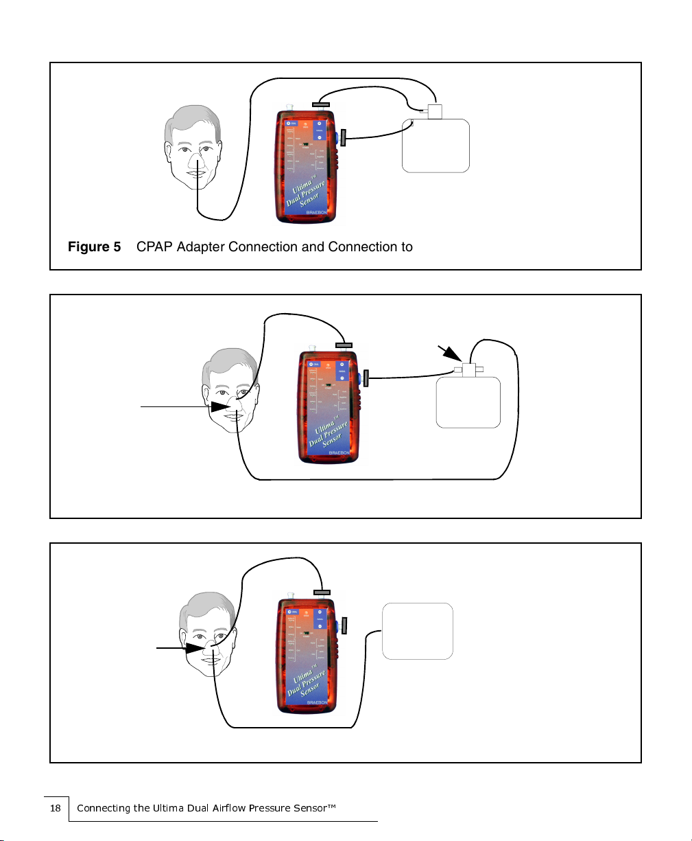
&RQQHFWLQJWKH8OWLPD'XDO$LUIORZ3UHVVXUH6HQVRU
Figure 5 CPAP Adapter Connection and Connection to the Nasal Differential Input
CPAP
Figure 6 CPAP Mask Connection and CPAP Tee Connection to the Nasal Differential Input
Tee
Connection
Tee Connection
CPAP
Tee Connection
Figure 7 CPAP Mask Connection
CPAP

&RQQHFWLQJWKH8OWLPD'XDO$LUIORZ3UHVVXUH6HQVRU
67(3 3RVLWLRQWKHFDQQXODRQWKHSDWLHQW
1. Position the Ultima Pressure Sensor Cannula on the patient and place the cannula sensor tips
into the nose and in front of the mouth as illustrated in Figure 8.
Figure 8 Positioning the Cannula
2. Once the nasal/oral prongs are comfortably placed, slide the cannula tubing over the patient’s
ears and down the front of the chest.
3. Slide the cinch tubing toward the neck for a comfortable fit under the chin.
4. Mount the pressure sensor on the wall or bedside table.
Warning: Always use a new single-use Ultima Airflow Pressure Cannula
(Model 0589, 0588, 0582s, or others) and a new Braebon™ safety filter (Model
0583) to prevent the spread of contaminants between patients and to prevent
damage to the pressure sensor.
Caution: If you are mounting the pressure sensor on the wall, mount the unit
upside down to minimize the likelihood of bending or kinking the cannula
tubing.

&RQQHFWLQJWKH8OWLPD'XDO$LUIORZ3UHVVXUH6HQVRU
67(3 $GMXVWWKH DLQLIQHFHVVDU\
The Ultima Dual Airflow Pressure Sensor™ contains four 20-turn potentiometers (pots) which
allow for precise adjustment of both gain and baseline settings for the nasal and oral outputs.
Under most circumstances, you will NOT need to make any adjustments.
$GMXVWLQJWKHJDLQ
You can enlarge or reduce the size of the waveform on the display by turning the gain screw
clockwise or counterclockwise respectively. You do not change the actual recorded signal when
you increase or decrease the gain.
7RDGMXVWWKHQDVDORURUDOJDLQ
1. To increase the gain (enlarge the waveform), turn the appropriate gain screw clockwise.
2. To decrease the gain (shrink the waveform), turn the appropriate gain screw counterclockwise.
$GMXVWLQJWKHEDVHOLQH
When you turn the baseline adjustment screw, you change the position of the waveform on the
display of your recording system. By turning the screw clockwise or counterclockwise, you
move the waveform further up or further down on the display so you can view the signal
peak-to-peak. The baseline is set to zero volts in the factory.
7RDGMXVWWKHQDVDORURUDOEDVHOLQH
1. Using the interface cable appropriate to your recording system, connect a 1 mm keyhole
connector to either the Nasal Airflow and Snoring output or the Oral Airflow and Snoring
output.
2. Connect the voltmeter to the interface cable.
3. Do the following:
• To move the baseline higher, that is increase the baseline voltage, turn the appropriate
baseline screw clockwise.
• To move the baseline lower, that is decrease the baseline voltage, turn the appropriate
baseline screw counterclockwise.
Caution: Do NOT adjust the baseline without a voltmeter.
This manual suits for next models
1
Popular Accessories manuals by other brands

Moonlight
Moonlight High Resolution Stepper Motor quick start guide

Atlantic Ultraviolet
Atlantic Ultraviolet Sanidyne PREMIUM owner's manual

Leviton
Leviton 5206-S00 Installation

Stahl
Stahl SolConex 8579/31 Series operating instructions

DLS
DLS BP-flexi75 owner's manual

Seeed
Seeed SYH24A1 instruction manual


