manuals.online logo
Brands
  1. Home
  2. •
  3. Brands
  4. •
  5. Moonlight
  6. •
  7. Accessories
  8. •
  9. Moonlight High Resolution Stepper Motor User manual

Moonlight High Resolution Stepper Motor User manual

MoonLite High Resolution Stepper Motor
MoonLite’s high resolution stepper motor option comes in three configurations.
•Stepper motor only or stand alone for $190.00 (customer pro ides controller)
•Stepper motor with MoonLite Mini V2 Controller for $440.00 (mini V2 controller by itself is $250.00)
•Stepper motor with MoonLite Dual Port DRO Display Focus Controller for $685.00 (controller by itself is
$495.00)
MoonLite’s high resolution stepper motor options use a premium, low backlash Hurst stepper motor. This pro ides ery
fine .00016” resolution (full step) and accurate position repeatability required for today’s high end imaging systems. The
stepper motor can also be ran in half step mode pro iding .00008” resolution, but it is recommended to run in full step
mode with most ASCOM software. The high resolution stepper motor is offered on all single rate focuser configurations.
It has such a fine ariable rate that the reduction unit is not needed, so it is not offered on dual rate focusers. Adding a
stepper motor gi es the CS and CF focusers a 7 lb. lifting capacity. Large format focusers such as the CRL, CSL, and
CFL are rated at 8 lb. ertical lifting capacity. Our small CR focuser has a 6 lb. load rating once installed. The stepper
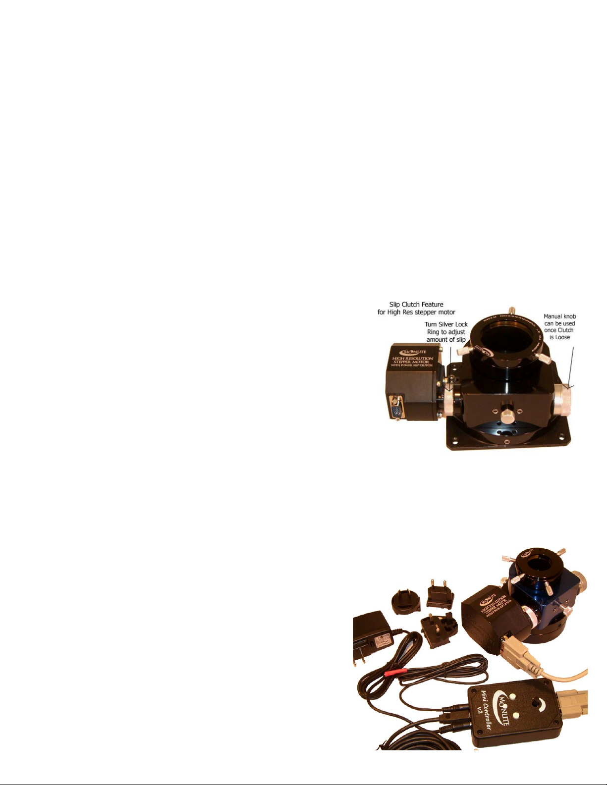
motor option features an adjustable slip clutch system so the focuser can be used manually or operated on motor at the
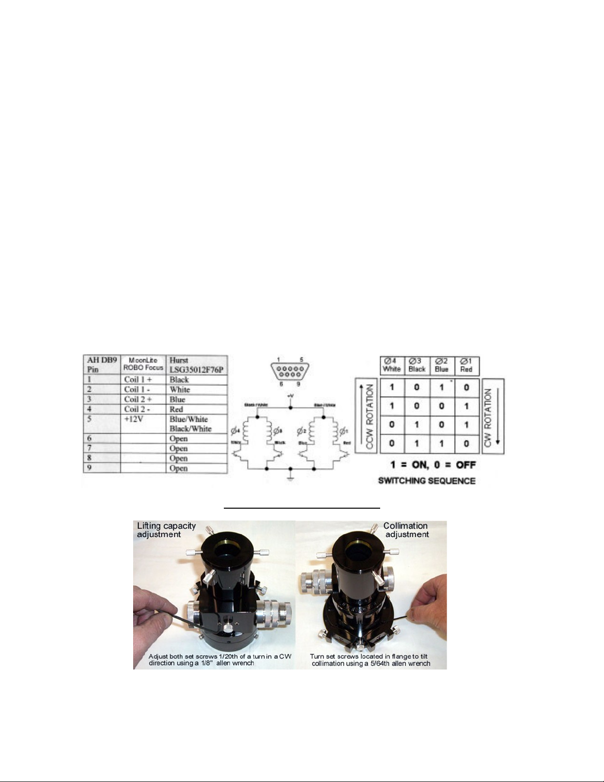
same time. The stepper motor’s 9-pin DBA connector is compatible with other stepper motor controllers such as ROBO
focus, as well as MoonLite’s controllers. A controller of some type must be used; the stepper motor cannot be directly
connected to a PC.
The amount of slip can be adjusted on the slip clutch by adjusting the
tightness of the slip clutch ring. For manual knob operation of the focuser,
turn the sil er knurled ring loose. For motor operation of the focuser,
tighten the sil er knurled ring. To adjust the knurled rings tension, it helps
to hold the manual knob still with your right hand and turn the clutch ring
with your left hand. Holding the manual knob in place will keep the shaft
from turning, allowing the clutch ring to tighten/loosen the clutch Note:
No damage will be done if the focuser motor continues to run past the
mechanical stops of the drawtubes tra el. E en if the clutch is tight, it will
simply slip when the tra el runs out.
In most cases, the stepper motor option is picked at the time of focuser purchase; howe er, we do offer a user installed
High Resolution Stepper Motor Kit for existing MoonLite focusers. The kit comes with different mounting brackets to fit
different MoonLite focuser models. Please see our web site for additional kit information showing the different brackets
a ailable for different model MoonLite focusers.
•The high resolution stepper motor only or stand alone option
is for customers that already ha e a ROBO focus controller or
other brand controller and do not need a stepper motor
controller. The stepper motor’s DB9 connector pin out is
100% compatible with the ROBO focus controller.
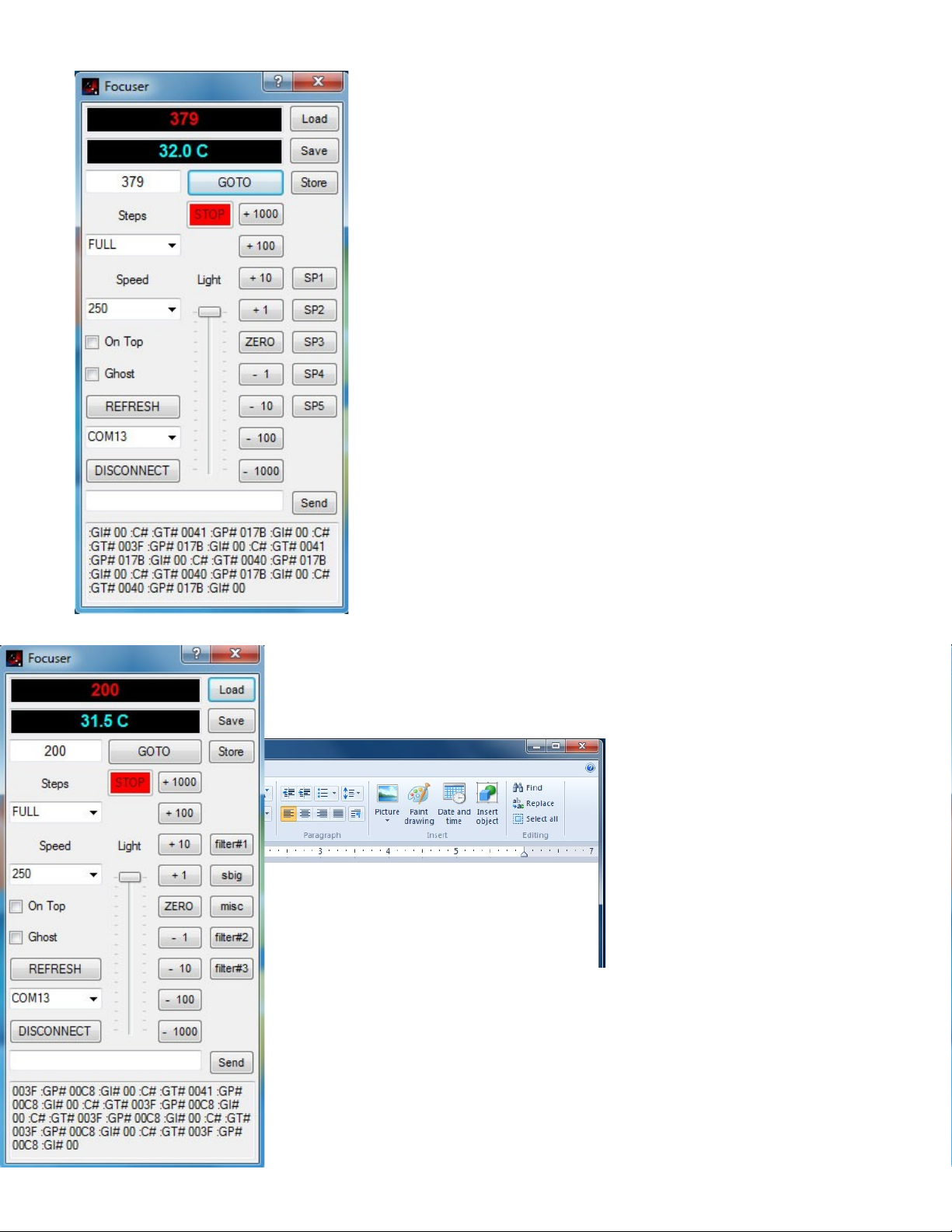
•The high resolution stepper motor with MoonLite Mini V2
controller uses an ASCOM compliant stepper motor
controller from MoonLite. The “Mini V2” controller works
with all ASCOM based software packages such as Focus
Max, CCDSoft, MaximDL, etc. It features a built in temp
sensor and also comes with a remote temp probe. We include
a USB cable and 12 olt AC adapter that has all the different
plug configurations (US, Europe, UK, and Australia);
howe er, most customers will simply use 12- olt power off
their mount. This mini V2 controller is designed to be used
remotely by a PC, or by the up /down buttons and speed
control knob on the controller. It has all the functions of our
larger DRO display controller below but no display. Our ASCOM dri ers and apps can be downloaded from our
site.
•The high resolution stepper motor with MoonLite’s Dual Port DRO Display Focus Controller can operate 2
high resolution stepper motors at the same time. Motor port #1 is for our existing high resolution stepper motor
for focusing. Motor Port #2 is for our soon to be released rotating flange system. This new controller will be able
to pro ide a complete 2 axis automated setup. The controller operates just like the Mini controller abo e, but has a
display to show position. It also comes with a remote temp probe.
Connection
MoonLite pro ides a 6 foot 9 pin DBA serial cable to
go from the controller to the high resolution stepper
motor on the focuser. The cable looks like a serial
cable; howe er, the signals from the controller to the
motor windings are not computer signals. We use the
first 5 pins in the cable to power the stepper motors
windings. Extra long (20’) serial cables are a ailable
if needed. Two cables are included with the dual port
DRO display controller for future use with the flange
rotator option.
A uni ersal AC adapter is included with all controllers
that will operate in different countries’ power (install
the matching plug style in the 12 olt AC adapter you
require). We include a 6 foot USB cable with the new
controller. Some customers use a USB hub for long
distance runs. A remote temp probe can be plugged
into the controller to bypass the built in temp probe located inside the case. Once plugged in, it will defeat the internal
temp sensor. The probe can be taped to the side of the telescope for better thermal reading of the OTA.
Basic Operation for the Dual port DRO display controller
First connect all cables and power up the controller using the power switch on the left side
Please note the boot sequence:
•The Display will go from Red, Green ,and Blue.
•Then display “MoonLite Telescope” and the ersion of the software “Ver 20”.
•It will then gi e a message “Press a button to enter menu”. Do not press any keys during that time, so the
controller can go in to normal operation. If you press a button at that time it will go into ad anced menu mode.
To get out of ad anced menu mode – just cycle the power off and back on.
Top line of display shows step count position for focus motor on port #1
Bottom line of display shows step count position for rotator motor on port #2
Right side of display will show the temp detected by either the internal or remote external
temp probe.
Red buttons will increase / decrease the focuser’s position (rack in / rack out).
Blue buttons will rotate the focuser, either right or left.
The focus steps are fine and slow when the button is first pressed , but will go faster if the
button is held down. Please remember to rack the focuser the whole way in to zero the
step count to the focusers fully racked in position (hold the button down until the focuser
is fully racked in. No harm will come to the focuser, as it will simply slip when hitting the
mechanical stops).
Advanced Menu Operation for the Dual Port DRO display controller
Press any key when prompted after unit is turned on.
etup Menu tructure:
Contrast Adjustment: Used to adjust the LCD contrast.
Red Brightness: The brightness of the RED LED backlight.
Green Brightness: The brightness of the GREEN LED backlight.
Blue Brightness: The brightness of the BLUE LED backlight.
Motor 1 Type: Selects Unipolar or Bipolar. (Bipolar is not supported at this time)
Motor 1 Direction: Selects the which way results in positi e step counts.
Motor 1 Half/Full: Selects if Motor 1 is Half stepped or full stepped. Half has double the resolution, but half the
speed. Focus cur e will need to be re-run if this is changed.
Motor 1 Units: The unit text to display. Steps or Degrees (for rotation).
Motor 2 Type: Selects Unipolar or Bipolar. (Bipolar is not supported at this time)
Motor 2 Direction: Selects the which way results in positi e step counts.
Motor 2 Half/Full: Selects if Motor 2 is Half stepped or full stepped. Half has double the resolution, but half the
speed. Focus cur e will need to be re-run if this is changed.
Motor 2 Units: The unit text to display. Steps or Degrees (for rotation).
Home Switch: Select which motor has the optional home switch. Used for zero setting
to a known point.
Temp Offset: Used to set the temperature offset for single point temperature calibration.
Temp Scale: Used to change the scaling to allow for two point calibration.
Reset To Defaults: Resets all of the abo e settings to the factory defaults. Acti ate by pressing both Blue Buttons at
the same time.
DONE? Exits the setup menu and sa es all settings to EEPROM. If a mistake was made, simply cycle power
without exiting, or use the “Reset to Defaults” option.
Expanded Commands:
The scale factor allows for stepped or scaled
mo es. If you ha e a filter wheel with a known
532 steps between positions, you can set the scale
factor to 532d or 0x0214. E ery button press
would then mo e 532 steps. Remote commands
remain unaffected by the scale.
The commands remain backward compatible with
the original DRO focus controller, but now add a
second channel, remote temperature sense, option
home switch, and an impro e user interface.
The motor mo e buttons are dual function. When
pressed for a short time, they mo e the motor in
ery fine increments at a slow speed. When held
down for longer periods of time, the motor speed
picks up and fast mo es are made.
erial Commands:
All commands are preceded by a “:” symbol and
finished with a “#” symbol. “x” represents a
hexadecimal digit.
Command Response Description
GP XXXX Get Current Motor 1 Positon, Unsigned Hexadecimal
GN XXXX Get the New Motor 1 Position, Unsigned Hexadecimal
GT XXXX Get the Current Temperature, Signed Hexadecimal
Comman
d
Respons
e
Description
POxx Adjust Temperature Offset, Signed
Hexadecimal
PSxx Adjust Temperature Scale, Signed
Hexadecimal
PRxx Adjust Red Backlight Brightness
PGxx Adjust Green Backlight Brightness
PBxx Adjust Blue Backlight Brightness
PCxx Adjust LCD Contrast
PXxxxx Adjust the Scale for Motor 1
Pyxxxx Adjust the Scale for Motor 2
PHxx Find home for Motor, alid options are “01”,
“02”
GD XX Get the Motor 1 speed, alid options are “02, 04, 08, 10, 20”
GH XX “FF” if half step is set, otherwise “00”
GI XX “01” if the motor is mo ing, otherwise “00”
GB XX The current RED Led Backlight alue, Unsigned Hexadecimal
GV XX Code for current firmware ersion
SPxxxx Set the Current Motor 1 Position, Unsigned Hexadecimal
SNxxxx Set the New Motor 1 Position, Unsigned Hexadecimal
SF Set Motor 1 to Full Step
SH Set Motor 1 to Half Step
SDxx Set the Motor 1 speed, alid options are “02, 04, 08, 10, 20”
FG Start a Motor 1 mo e, mo es the motor to the New Position.
FQ Halt Motor 1 mo e, position is retained, motor is stopped.
Example: To set a new position: :SN0537#
For motor 2 all of the above commands are available, just precede the command with a “2”.
Motor 2 Example: To set Motor 2 to a new position: :2SN0537#
MoonLite Mini V2 controller Layout
Please note the internal temp sensor will be used if no remote temp probe cable is plugged in to the controller. Once the
remote temp probe is plugged in the controller it will not use the internal unit. Manual buttons will o er ride and mo e the
focusers position reported in the software. Note speed control knob can go from no mo ement at all (full CCW) to a
moderate rate (full CW) setting. Re zero focuser step count by racking the drawtube the whole way down in to a fully
racked in position and also zero the count in the software to match.
Both Mini V2 controllers and the Dual port DRO display controller work
with all ASCOM based software packages such as Focus Max, CCDSoft,
MaxumDL, Sequence Generator Pro, Equinox Pro, and so on.
MoonLite offers both 32 and 64 bit dri ers. We also offer 2 simple
non ASCOM programs for customers not running a full blown
ASCOM automated system (a simple automated control app to run the
focuser). Single port 1.07 ersion software and FCP V2 for the Dual
port controller.
MoonLite’s 1.07 NON ASCOM software program (photo at left).
Version 1.07 will work with all MoonLite controllers. The original
Mini controller, new Mini V2 controller, DRO display controller, and
the new Dual port DRO display controller for Rotation. Howe er it
will only operate the first port when connected to the new Dual port
DRO display Rotator controller.
The latest 1.07 ersion of the software has 5 user defined buttons for
customers to store step count positions that are frequently used. Just go
to the step count you want and then click Store and the SP button you
want to assign the step count alue to. Once finished with storing all 5
button alues click Sa e and then pick a directory to sa e the info.
In this case I sa ed the file to a directly called camera positions. Once
sa ed I can then open the file in Word pad and modify the text for the 5 buttons to
label them anything that is required. Note the old SP1 button now says filter#1
and will go to a step count of 100 if clicked. Then when I hit Load and indicate
the file, it will now rename all of the buttons.
The Software also has a Serial data
log feature at the bottom. This
allows you to monitor
communications with the focuser
and also send serial commands to
the controller. Example if you want
to adjust/ calibrate the temp display,
just type in PO02 in in the box and
hit send. This will change the temp
positi e by 1 degree. A PO04
command would adjust it by 2
degrees. A POFC command would adjust it -2 degrees. All serial commands are in
Hex. Please see serial commands later in this document for more information.
Please see the download section of our
web site for all dri ers and software
downloads.
http://www.focuser.com/downloads.shtml
For controlling the focuser with your
current imaging software, we personally
like Focus Max and it is free to download
at the following website.
http://users.bsdwebsolutions.com/~larryweber/ (Sample screen shot of Focus Max)
Computer Connection Operation
Connect the controller to your PC using USB. Windows should
show new hardware found and install the de ise automatically.
If your laptop is older, you may need to install the latest USB
dri er. To install the dri er download the VCP ( irtual com port)
dri er for the FT232R chip from
http://www.ftdichip.com/Dri ers/VCP.htm Unzip using your
fa orite zip file utility to a directory of your choice. Connect
power to the focus controller and the USB cable to your computer
and the focus controller. Windows will state that it has found new hardware and needs to install dri ers. When
prompted, select “Ha e Disk” and select the directory where the files were unzipped. The installer should then
complete the software installation.
Please make sure you ha e downloaded and installed the latest ersion of ASCOM http://ascom-standards.org/
Please download our most current ASCOM dri er from our website. Installation documentation and the dri ers
are located here http://www.focuser.com/downloads.shtml Please see our tutorial for setting up the focuser to
run with Focus Max at http://www.focuser.com/cgi-bin/dman.cgi?page=fmflw
Generic serial commands can be used to operate the controllers if needed. Please see table below for
command set.

   
   
          
          !"#$%#$
"#&'()#*+
$,-+#.
$#$"##"*
 / -        -.",011110
#*
 / 2        !,",(#$*
 -        33 "#4#.33
.56678#"9'*
 - :       33 #""6,.33
.566'*:
#(("$*
 - ;       ))<// 0//0((#(5""
.0))0
 - !       ))<) 0))0((#$6=
.0)0
 -        1111 .""$,,
011110#.1111(56
6'*
 - >       1111 #".1111
(566'*
 - +       1111 #".1111
(56678#"9'*
 -        :: -$(?..56
#.?6@
$=#6
$*
   3 3      ."#4#.33
.56=678#"9'*
  : 3 3      .""6,.33.56=
6'*$)=
)=)=))=.##"""6
,()===""#
"#$,*
  /        (5"*
  ;        (5"*
   1 1 1 1    .".1111(56
6'*
  > 1 1 1 1    #".1111(56
6'*
 A         #$"#"(#6*
 5         :"#"(#6*
 > < 3 3      +"#B=33.56
6'=(6#*
C'"><)B(AD
C'"></EB(5*D
DB9 cable pin out and Stepper motor winding pin out.
We use a high quality Hurst unipolar 12 olt stepper motor with a fairly high reduction gearbox. There is a ery
small amount of backlash noted with this unit. MoonLite controllers will release idle current to the motor
windings when not mo ing to reduce current consumption and also reduce heat generated by the motor itself;
howe er some controllers like ROBO focuser and others will keep the current draw continuous when not in
motion. That can cause the motor to get warm; howe er it will not damage the motor.
Mechanical adjustment section
Lifting Capacity: The drawtube pressure can be adjusted to each user’s preference. Increasing the pressure
increases the load capacity ( ertical lifting capacity) of the focuser. Decreasing the pressure lowers the load
capacity but gi es the focuser a smoother focusing action. We set the focuser at approximately 5 lbs. at time of
assembly; howe er, you can adjust it to be more depending on your specific needs. The ideal setting is to ha e
it adjusted so the focuser can hold the hea iest load presented without slipping and requiring no additional
force. This will gi e the focuser the best feel and still pro ide the ertical lifting capacity required. To adjust
the lifting capacity, turn the aluminum thumbscrew located between the two setscrews on the bottom of the
focuser clockwise (CW) to increase load capacity. The aluminum thumbscrew can only add pressure, not take
away pressure. This is due to the 2 setscrews on each side of the thumbscrew applying a minimum set pressure
amount. In some rare case it may be necessary to do a coarse adjustment by turning the 2 setscrews located on
each side of the aluminum thumbscrew (1/8 Allen wrench is needed) a ery small amount. Normally, 1/20th of a
turn or less should be made on the setscrews in a CW direction, then check
the lifting capacity pressure by racking the drawtube up and down with your
hea iest load. Note: excessi e pressure adjustment o er 1/20th of a turn can
crack the bearings!
•Collimation: To adjust collimation, turn the 4 mini
setscrews located in the top part of the 2-part flange. A
small amount of tip/tilt (.015 max) can be made by
adjusting the setscrews. We collimate each focuser
dead on before shipping it so no adjustment should be
required; howe er, if collimation is required due to
some sort of OTA defect when the focuser is installed,
then the tip/tilt ability of the focuser's flange will come
in handy. Please Note: rotating the focuser will throw
off any collimation reference once the flange is tilted
off plane. So please do not collimate the focuser off
center line unless it is absolutely necessary to fix a
gross error in the OTA.
•Performance: To maintain the CF focusers
performance, keep all bearing and shaft riding surfaces
clean on the drawtube. All crayford style focusers
require a clean bearing to drawtube surface for smooth
operation. The drawtube has been polished to remo e
all machine marks and hard anodized resulting in the
action ha ing a super smooth feel. Keeping the
surfaces clean will keep the focuser operating at
optimal performance. Note: Some wear marks on the
drawtube are normal o er regular use and do not cause
any performance issue; howe er, excessi e wear marks
on the drawtube can be seen if the drawtube is not
clean. Airborne contaminates on the drawtube surface
can get crushed between the bearings and the drawtube
surface. The crushed particles will be abrasi e causing
the drawtube’s anodized surface to wear quicker than normal. Please keep the drawtube clean, especially
in sandy/windy areas.
•Reduction Unit: Dual rate focuser owners may want to break in the 8:1 reduction unit by running it up
and down when first recei ing the focuser. It is adjusted fairly tight at the time of assembly and requires
a little use to come up to peak performance. No maintenance should be required on the reduction unit as
it is packed with lithium low temperature grease for the life of its operation.
Motor Trouble hooting guide
The amount of slip can be adjusted on the slip clutch by adjusting
the tightness of the slip clutch ring. For manual knob operation of
the focuser, turn the sil er knurled ring loose. For motor operation
of the focuser, tighten the sil er knurled ring. To adjust the
knurled rings tension, it helps to hold the manual knob still with
your right hand and turn the clutch ring with your left hand.
Holding the manual knob in place will keep the shaft from turning,
allowing the clutch ring to tighten/loosen the clutch
Focuser adjustment guide for motor options if focuser slips
under heavy loads. Slipping can be caused be either a loose clutch
setting or drawtube to shaft pressure setting to low. Check mo ement of manual knob to erify what adjustment
is needed. If the manual knob on the right does not turn when the focuser is slipping, then the slip clutch is is
not tight enough on the motor.( tighten clutch as shown in motor documentation). If the manual knob on the
right is mo ing but the drawtube is not mo ing, then the drawtube is slipping and the shaft to drawtube pressure
needs increased a small amount. See lifting capacity adjustment shown abo e.
To erify motor is mo ing, check the black hub part of the clutch that is connected to the motor shaft for
motion. If you look carefully at the black nub that attaches to the motor, you may be able to see it turn as a
small set screw should be noted turning around with the black hub. The black hub is on the left side of the slip
clutch. The black larger pad side of the clutch is set screwed on to the main shaft. As the motor turns the small
black hub part of the clutch will mo e with it. It is set screwed on to the motor shaft. This is a good way of
testing to see if the motor is actually mo ing. The whole clutch as a unit should rotate with the motor if it is
tight. If it is loose, then only the small hub on the motor side will be turning with the motor.
MoonLite Telescope Accessories, 755 Preser e Road, Dan ille PA 17821, 570-437-2232
www.focuser.com Re 09/13

Popular Accessories manuals by other brands

Ezviz DB2 Pro manual

Ezviz

Ezviz DB2 Pro manual

4B WDB81 Series installation instructions

4B

4B WDB81 Series installation instructions

ELTEX SMG 156 Instructions for use

ELTEX

ELTEX SMG 156 Instructions for use

Emos P5729B manual

Emos

Emos P5729B manual

Philips SB7G17B Specifications

Philips

Philips SB7G17B Specifications

Mutec REF 10 manual

Mutec

Mutec REF 10 manual

Intenso XS20000 user manual

Intenso

Intenso XS20000 user manual

emerio EBL-123277.3 instruction manual

emerio

emerio EBL-123277.3 instruction manual

Laser PW-W3 Quick start user guide

Laser

Laser PW-W3 Quick start user guide

Manitowoc G-0800 installation instructions

Manitowoc

Manitowoc G-0800 installation instructions

Aeon Labs Aeotec MULTISENSOR 6 user guide

Aeon Labs

Aeon Labs Aeotec MULTISENSOR 6 user guide

Siko MSAC501 Original Installation Instructions

Siko

Siko MSAC501 Original Installation Instructions

Seifert SlimLine Pro KG 8506 instruction manual

Seifert

Seifert SlimLine Pro KG 8506 instruction manual

Garmin GDL 90 UAT Upgrade instructions

Garmin

Garmin GDL 90 UAT Upgrade instructions

Lillipad Diving Board owner's manual

Lillipad

Lillipad Diving Board owner's manual

Elko INELS RF Control RFSC-61 manual

Elko

Elko INELS RF Control RFSC-61 manual

PNY PowerPack L1500 user manual

PNY

PNY PowerPack L1500 user manual

IFM Electronic efector500 PQ08 Series operating instructions

IFM Electronic

IFM Electronic efector500 PQ08 Series operating instructions

manuals.online logo
manuals.online logoBrands
  • About & Mission
  • Contact us
  • Privacy Policy
  • Terms and Conditions

Copyright 2025 Manuals.Online. All Rights Reserved.