Brain Bee OPA-100 User manual
SERVICE MANUAL
TECHNICAL INFORMATION
REV. 1.0
SMOKEMETER
OPA-100

OPA-100 INDEX
MS0100-06-0_service_manual.doc 2/22 INTRODUCTION
INDEX
1
INTRODUCTION..........................................................................................................................3
1.1
CONTENTS
OF
THE
MANUAL.............................................................................................3
2
SAFETY GENERAL INFORMATION.......................................................................................4
2.1
IMPORTANT
INFORMATION
FOR
SAFETY......................................................................4
2.2
SYMBOL..................................................................................................................................5
2.2.1
SAFETY..........................................................................................................................................5
2.2.2
MARCATURA................................................................................................................................5
3
INSTALLATION AND SERVICE OPERATIONS ...................................................................6
3.1
VERIFY
COMPONENTS ........................................................................................................6
3.1.1
SYSTEM N. 1 : PC+AGS-200+OPA-100.......................................................................................6
3.1.2
SYSTEM N. 1 : PC+AGS-200+OPA-100.......................................................................................7
3.2
SOFTWARE
UPDATE.............................................................................................................8
3.3
INITIAL
VERIFICATION ....................................................................................................... 8
3.3.1
EXTERNAL VISUAL CHECK ......................................................................................................8
3.3.2
INTERNAL VISUAL CHECK (ONLY FOR AUTHORIZED TECHNICIAN) ............................9
3.3.3
CHECK POWER SUPPLY.............................................................................................................9
3.3.4
CHECK WARM-UP LOCKOUT..................................................................................................10
3.3.5
CHECK ZERO AUTOMATIC ADJUSTMENT...........................................................................10
3.3.6
EXECUTE FILTER CALIBRATION...........................................................................................10
3.3.6.1
Filter ..........................................................................................................................................10
3.3.6.2
Opacity calibration procedure...................................................................................................11
3.4
SUBSEQUENT
VERIFICATION.......................................................................................... 12
3.5
ROUTINE
TESTING.............................................................................................................. 12
4
TECHNICAL DOCUMENTS.....................................................................................................13
4.1
A
SYSTEM
OVERVIEW.......................................................................................................13
4.2
INTERNAL
CABLES ............................................................................................................14
4.2.1
Cables View...................................................................................................................................14
4.2.2
124010001700 Internal OMNIBUS cable for Power supply and RS485 network.........................16
4.2.3
124010001500 Internal cable for Temperature probe input...........................................................16
4.2.4
124010000800 Internal cable for RPM Piezo input.......................................................................17
4.2.5
124010001600 Internal cable for RS232 Interface ........................................................................17
4.2.6
125010000900 Internal cable for antenna to receive from MGT-300/R........................................18
4.2.7
124010001000 Cable for Led of Chamber Light Emission ...........................................................18
4.2.8
124010001100 Cable for Photodiode Chamber light receiver.......................................................19
4.2.9
124010000900 Internal cable for LM35 Chamber temperature.....................................................19
4.2.10
125010002400 Internal cable connected to Fan Side Emission Side Receiver..............................20
5
OTHER INFORMATION...........................................................................................................21

INTRODUCTION OPA-100
INTRODUCTION 3/22 MS0100-06-0_service_manual.doc
1 INTRODUCTION
1.1 CONTENTS OF THE MANUAL
This manual is for the TECHNICAL SERVICE department and is an aid for repair and servicing of the
OPA Diesel Smokemeter.
The manual is made with different chapters:
Chapter 2 SAFETY GENERAL INFORMATION
Chapter 3 INSTALLATION AND SERVICE OPERATIONS
Chapter 4 TECHNICAL DOCUMENTS
Chapter 5 OTHER INFORMATION
________________________________________

OPA-100 SAFETY GENERAL INFORMATION
MS0100-06-0_service_manual.doc 4/22 SAFETY GENERAL INFORMATION
2 SAFETY GENERAL INFORMATION
2.1 IMPORTANT INFORMATION FOR SAFETY
During the installation and the execution of operative procedure, some important rules for individual
safety must be observed.
All operations described in this manual must be done by
trained people
In order to move heavy loads or to use any tools it is
compulsory to put on protection gloves
In order to use tools (drill, saw) it is compulsory to put on
protection glasses
It is forbidden raising loads heavier than 22 kg per person
without lifter
Remove main power and use tools with insulate handle
before handling inside the instruments
Respect carefully all indications in this manual or in other
linked manuals
SAFETY GENERAL INFORMATION OPA-100
SAFETY GENERAL INFORMATION 5/22 MS0100-06-0_service_manual.doc
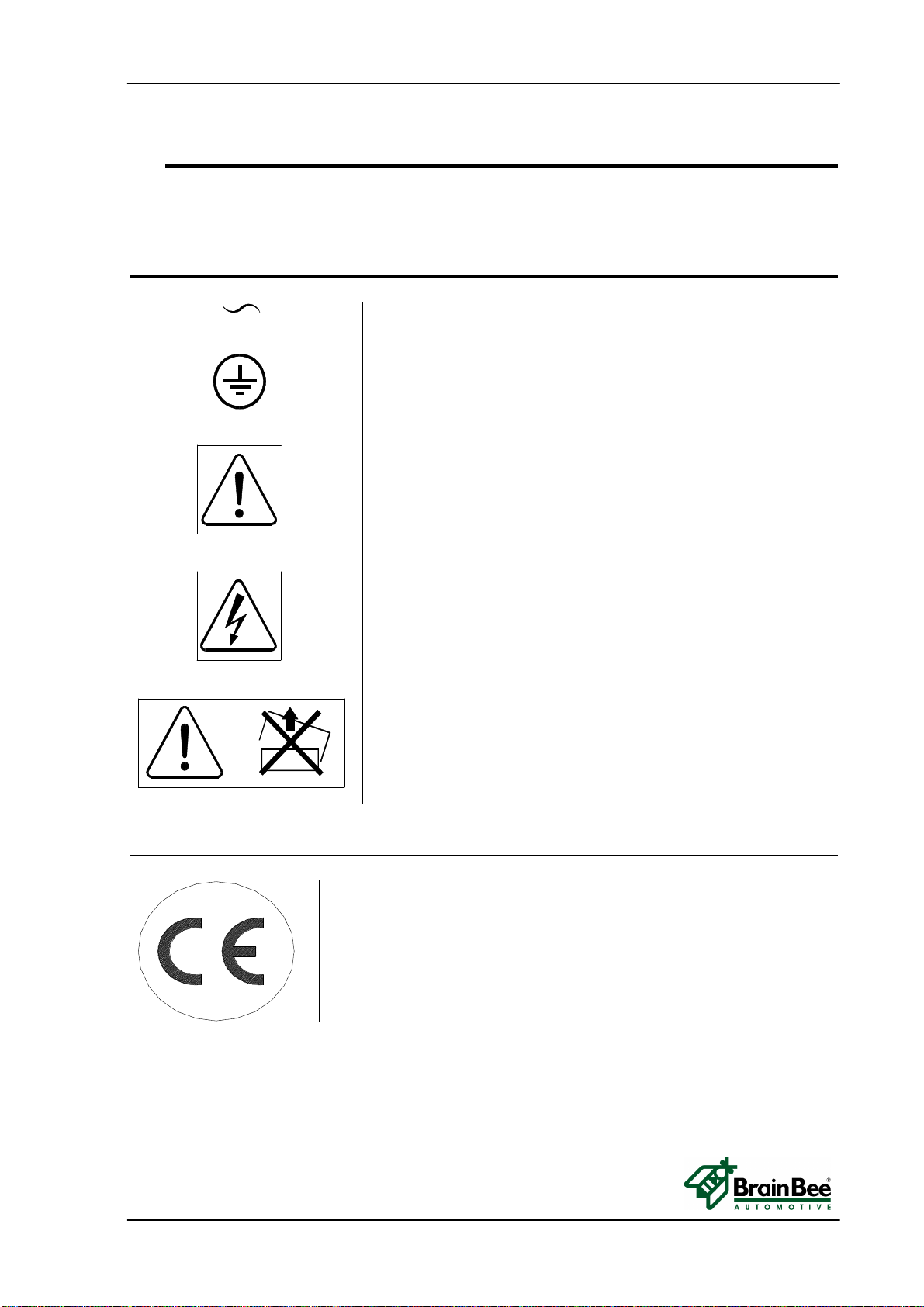
2.2 SYMBOL
This paragraph explains all safety symbols you might find on the devices.
2.2.1 SAFETY
ALTERNATE CURRENT
GROUND
READ MANUAL INSTRUCTION
ATTENTION ! ELECTRICAL SHAKE
ATTENTION ! DON’T REMOVE THE COVER
(reserved operation only for technical department)
2.2.2 MARCATURA
CE BRAND
OPA-100 INSTALLATION AND SERVICE OPERATIONS
MS0100-06-0_service_manual.doc 6/22 INSTALLATION AND SERVICE OPERATIONS
3 INSTALLATION AND SERVICE OPERATIONS
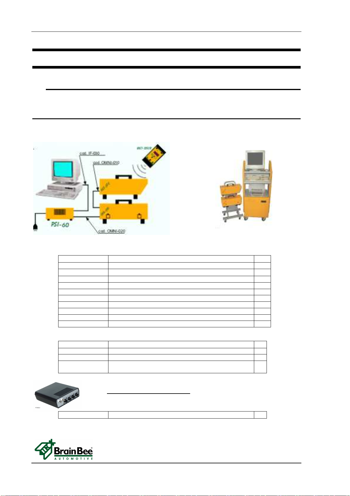
3.1 VERIFY COMPONENTS
Verify the availability of the components to install in your system:
3.1.1 SYSTEM N. 1 : PC+AGS-200+OPA-100
CODE DESCRIPTION Qt.
SW-800 OMNIBUS-800 software 1
AGS-200 Exhaust gas module 1
OPA-100 Smokemeter module 1
PSI-50 Power supplìer 1
MGT-300/R (*) RPM Counter radio transmission 1
IF-030 PC connection cable 1
OMNI-020 Connection cable PSI/AGS/OMNIBUS (4 m.) 1
CMNI-010 Connection cable PSI/AGS/OMNIBUS (0.4 m.) 1
TRO-030 AGS/OPA trolley 1
TRO-020 Roll-stand for PC 1
(*) alternative : MG-7000 + MG-7011 (modulo radio-radio module)
In case MGT-300/R is not required, replace the code with following items :
ST-020 Temperature probe AGS/OPA (6 m.) 2
CPI-020 RPM Inductive clamp 1
RPM-020 Diesel RPM cable for piezo transducer (6 m.) 1
TSD-010 Piezo transducer diesel RPM reading for OPA-100 (d.6
mm) 1
DMO-810 Oscilloscope kit for PC with cables 1
OSCILLOSCOPE FUNCTION :
INSTALLATION AND SERVICE OPERATIONS OPA-100
INSTALLATION AND SERVICE OPERATIONS 7/22 MS0100-06-0_service_manual.doc
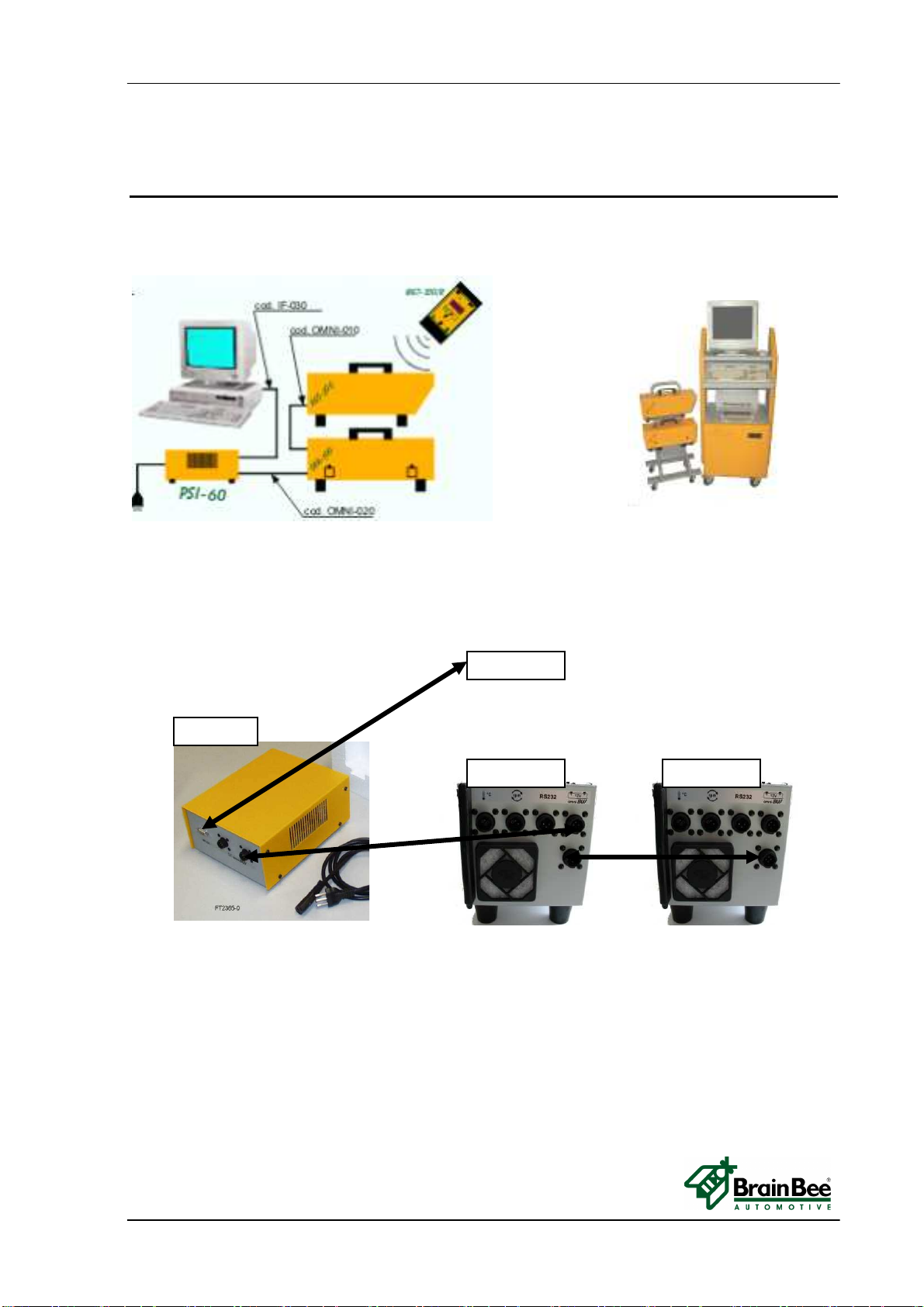
3.1.2 SYSTEM N. 1 : PC+AGS-200+OPA-100
OPA
-
100
PSI
-
60
AGS
-
200
COM PC

OPA-100 INSTALLATION AND SERVICE OPERATIONS
MS0100-06-0_service_manual.doc 8/22 INSTALLATION AND SERVICE OPERATIONS
3.2 SOFTWARE UPDATE
In order to update the instrument you can use special software where you can find on line
instructions with the required cables and connections.
You can get software via the internet (www.brainbee.com) or by our CD Rom
3.3 INITIAL VERIFICATION
The initial verification of the instruments may include the following tests:
3.3.1 EXTERNAL VISUAL CHECK
•Perform an external visual check. The plates/labels must be readable. The seal must
not be broken. The eight screws of the cover must be present and fixed securely.
•Verify that the same serial number printed next to the barcode label is the same as on
the printouts.
•Verify the presence and the status of the glasses.
Three elements must be present:
2 x protective frames with transparent glass
1 x open frame without glass
•Pull out the three frames. Cleans the glasses with a soft cloth or optical cleaning wipe as
used to clean glasses. Re-insert the glass lenses after cleaning.
AGS
-
200
Open frame transparent glass transparent glass
Serial number

INSTALLATION AND SERVICE OPERATIONS OPA-100
INSTALLATION AND SERVICE OPERATIONS 9/22 MS0100-06-0_service_manual.doc
3.3.2 INTERNAL VISUAL CHECK (ONLY FOR AUTHORIZED TECHNICIAN)
DANGER!
TO AVOID BURN ON YOUR HANDS DO NOT TOUCH UNCOVERED PARTS OF
MEASUREMENT CHAMBER
TO AVOID CRUSHING YOUR FINGERS DON’T TOUCH THE ZERO ELECTROVALVE
WHEN POWER SUPPLY IS ON
•Remove the cover by unscrewing the eight black screws.
•Check the integrity of pneumatic and electric circuits.
Fan (side rx light) - empty frame - frame with glass - zero electro valve - frame with glass – Fan (side tx light)
Run software of Smokemeter and wait for warm-up to finish.
After warm-up, the OPA-100 performs an autozero adjustment.
During the autozero adjustment the electro valve turn on and the two fans will start .
Check the fans turn properly.
The red led on the electronic board flashes 1 pulse/sec to signal a correct working status.
If led flashes slow (1 pulse/3 sec) OPA-100 is waiting for communication with PC.
If led flashes fast (5 pulse/1 sec) the OPA-100 signals a warning state with an internal
error.
To view internal errors, from the Smokemeter menu select F6 (Control) and then F8
(Status OPA-100).
3.3.3 CHECK POWER SUPPLY
Check the power supply voltage and frequency at the location of use to determine compliance
with the specifications on the measuring instrument’s label.
The OPA-100 power supply range must be from 11 to 15 VDC.
You can measure power supply voltage value by a voltmeter between pin 1(+) and 4(-) of
the OMNIBUS CABLE connected to the power supply.

OPA-100 INSTALLATION AND SERVICE OPERATIONS
MS0100-06-0_service_manual.doc 10/22 INSTALLATION AND SERVICE OPERATIONS
3.3.4 CHECK WARM-UP LOCKOUT
Check the activation of the warm-up lockout by attempting to make a measurement within 1
min of initial power-on of the instrument.
Turn off OPA-100, after some minutes turn on, check the activation of warm up message
and verify you are unable to perform any smoke measurement and tests.
3.3.5 CHECK ZERO AUTOMATIC ADJUSTMENT
Check if the automatic zero adjustment works properly.
•Verify proper insertion of the frames in the chamber, they must be all inserted.
•Select F1 (continuous test) then press F2 to start with a zero adjustment.
•Verify at the end of the autozero adjustment the opacity display value should read 0 m-1
3.3.6 EXECUTE FILTER CALIBRATION
After the instruments has been checked and the warm up is finished, perform the filter
calibration.
3.3.6.1 Filter
PAY ATTENTION!
Make sure the filter has been properly cleaned with a glasses cleaning cloth.
DURING THIS PROCEDURE DO NOT TOUCH THE FILTER GLASS WITH FINGERS!
•Use the filter provided with OPA-100
Opacity value
INSTALLATION AND SERVICE OPERATIONS OPA-100
INSTALLATION AND SERVICE OPERATIONS 11/22 MS0100-06-0_service_manual.doc
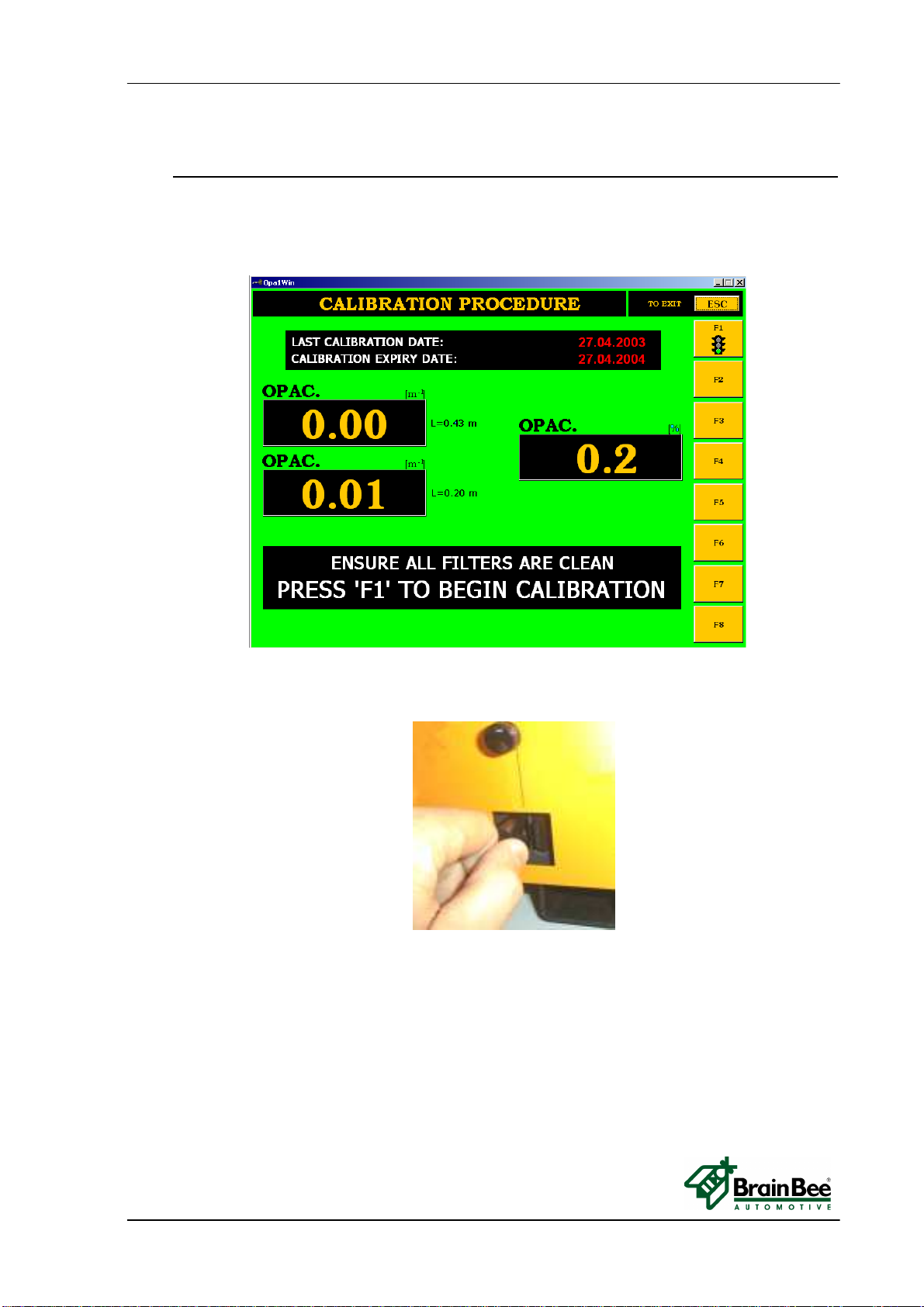
3.3.6.2 Opacity calibration procedure
•From the Smokemeter menu select “SERVICE” (F7) ,and insert the password.
•Now select
“Official calibration” (F2) .
•Select “F1”
•Wait until the autozero has finished.
•
•Insert the calibration filter into the hole of the empty frame
•Insert the value of the filter into the box displayed on the display.
•Press ENTER when ready and the automatic calibration will start.
•After the message CALIBRATION COMPLETE, press ENTER to confirm the end
of operation
•Press ESC to return in the main menu
•Select “Control”(F6) ;
•Select “Last calibration date”(F1).
•Verify that the correct date of calibration has been set.
•Select ESC to exit

OPA-100 INSTALLATION AND SERVICE OPERATIONS
MS0100-06-0_service_manual.doc 12/22 INSTALLATION AND SERVICE OPERATIONS
3.4 SUBSEQUENT VERIFICATION
Subsequent verification of an instrument at the same location may include the following tests.
•For any subsequent verification clean up the glasses and probe.
•For short-term subsequent verification, perform all tests included in the initial verification
except for the power check and the warm-up check.
•For short-term subsequent verification, perform a filter calibration using the filter provided with
OPA-100.
•For long-term subsequent verification, perform all tests included in the initial verification.
•When the instruments have been moved to a new location (e.g. change in business address
as defined by the responsible legal authority), or have undergone repairs other than the
replacement of probe, perform all tests included in the initial verification.
3.5 ROUTINE TESTING
A routine test of the instruments should consist of at least the following.
•Perform an external visual control.
Clean the glass lenses and the sample probe.
Pay attention to every screen message.

TECHNICAL DOCUMENTS OPA-100
TECHNICAL DOCUMENTS 13/22 MS0100-06-0_service_manual.doc
4 TECHNICAL DOCUMENTS
The electrical diagrams are not enclosed in this manual because in case of electronic failure cards
must be replaced. In this chapter there is just cable and the connection diagrams.
4.1 A SYSTEM OVERVIEW
Connection
panel
Smoke input
Electronic Board
Cables
Measurement Chamber
with -TX light - RX light – Heating resistors
Smoke Input Tube
Zero Electro valve
Glasses Frames Holes
Fans
Tubes
OPA-100 TECHNICAL DOCUMENTS
MS0100-06-0_service_manual.doc 14/22 TECHNICAL DOCUMENTS
4.2 INTERNAL CABLES
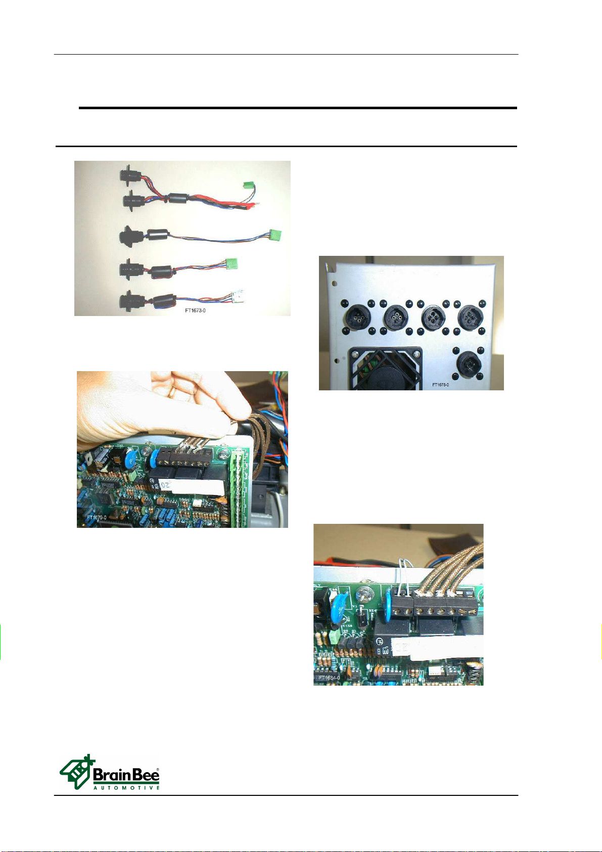
4.2.1 Cables View
In the photo you can see:
1. Cable 1240100017XX ( omniBUS);
2. Cable 1240100016XX ( RS-232 );
3. Cable 1240100008XX ( RPM );
4. Cable 1240100015XX ( temp/prog).
Heating Resistor connections
(about 3,3 ohm each)
Electro valve coil connections (unpolarized
wires)
4 3 2 1
1
TECHNICAL DOCUMENTS OPA-100
TECHNICAL DOCUMENTS 15/22 MS0100-06-0_service_manual.doc
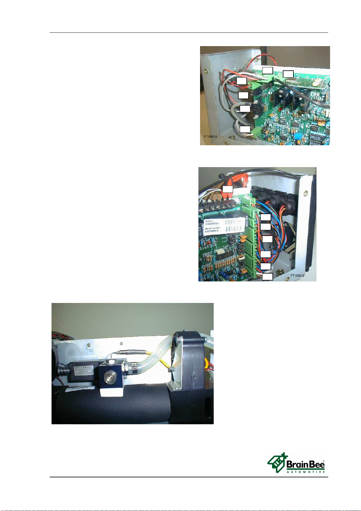
1. 125010000900 antenna cable;
2. 124010000900 LM35 temp. chamber sensor);
3. 125010002400 cable Fan Emission Side;
4. Thermocouple cable;
5. Tube T4S0205 from measurement chamber
6. 124010001000 Cable for Led .
1. 124010001700 cable for Power supply;
2. 125010002400 cable Fan Receiver Side;
3. 124010001700 cable for RS485 network;
4. 124010001600 cable for RS232;
5. 124010000800 RPM Piezo input;
6. 124010001500 Temperature probe;
7.
124010001100 Cable for Photodiode
.
Thermocouple smoke temperature
1
2
3
4
5
6
7
1
2
3
4
5
6
OPA-100 TECHNICAL DOCUMENTS
MS0100-06-0_service_manual.doc 16/22 TECHNICAL DOCUMENTS
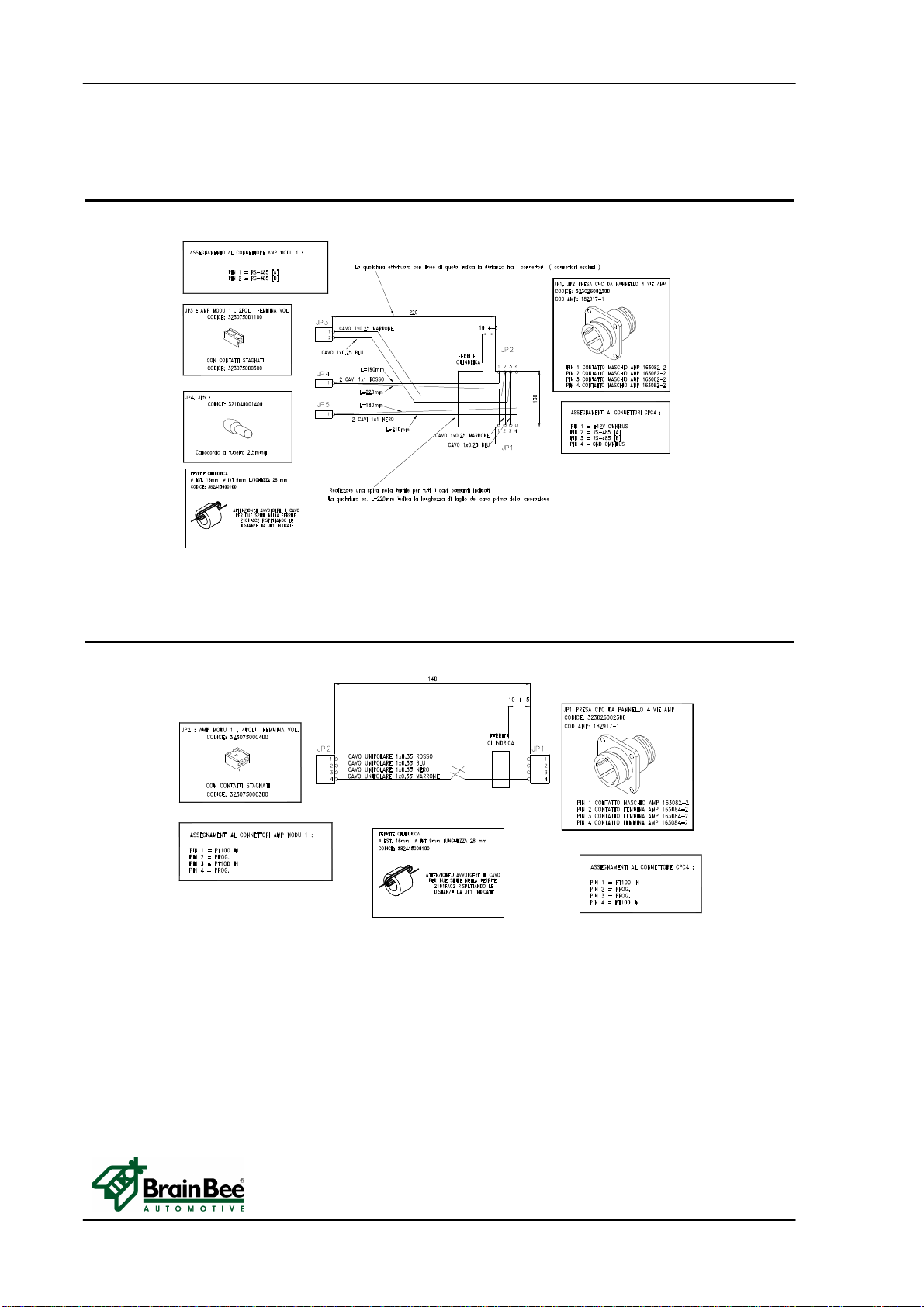
4.2.2 124010001700 Internal OMNIBUS cable for Power supply and RS485
network
4.2.3 124010001500 Internal cable for Temperature probe input

TECHNICAL DOCUMENTS OPA-100
TECHNICAL DOCUMENTS 17/22 MS0100-06-0_service_manual.doc
4.2.4 124010000800 Internal cable for RPM Piezo input
4.2.5 124010001600 Internal cable for RS232 Interface
OPA-100 TECHNICAL DOCUMENTS
MS0100-06-0_service_manual.doc 18/22 TECHNICAL DOCUMENTS
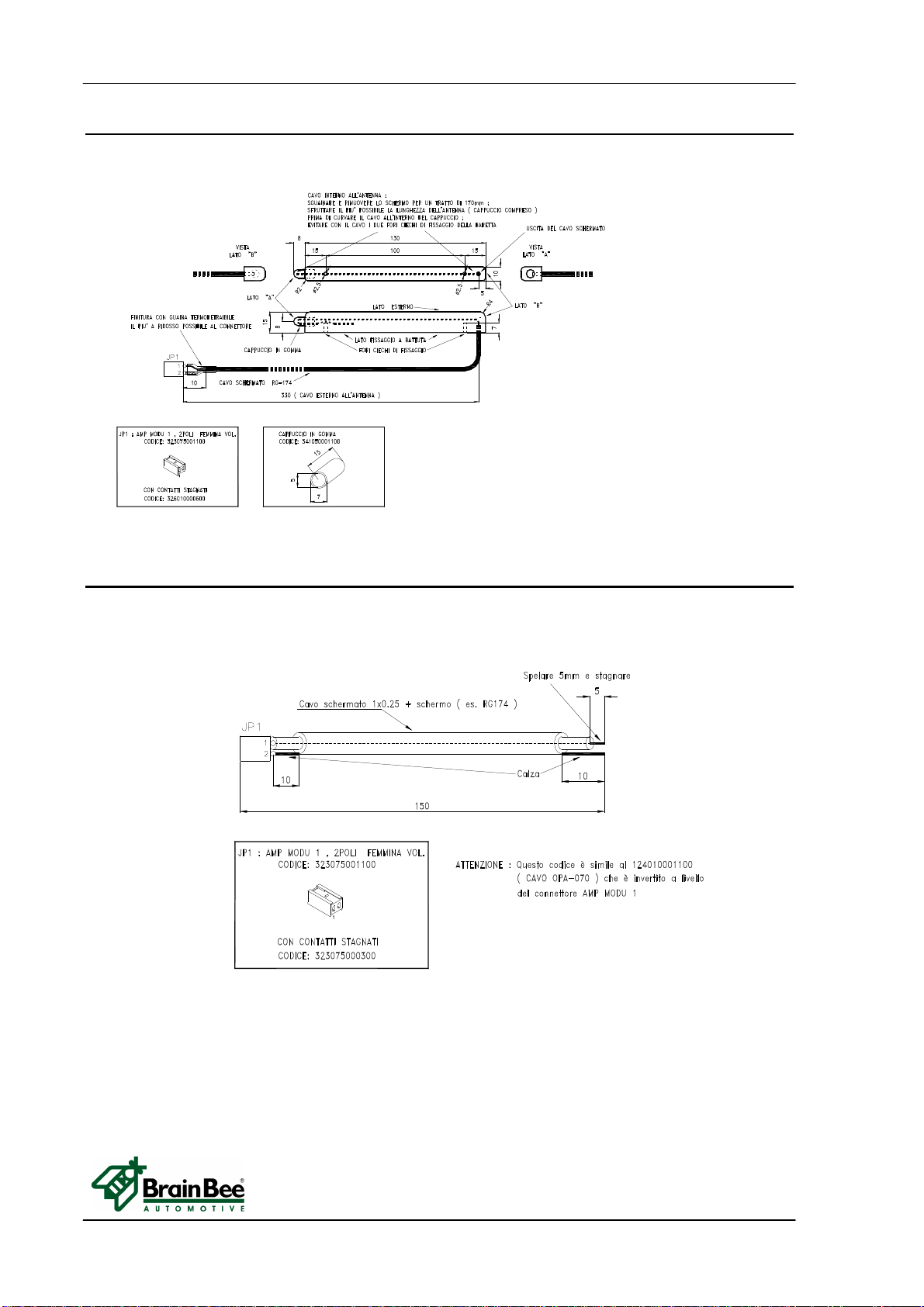
4.2.6 125010000900 Internal cable for antenna to receive from MGT-300/R
4.2.7 124010001000 Cable for Led of Chamber Light Emission
TECHNICAL DOCUMENTS OPA-100
TECHNICAL DOCUMENTS 19/22 MS0100-06-0_service_manual.doc
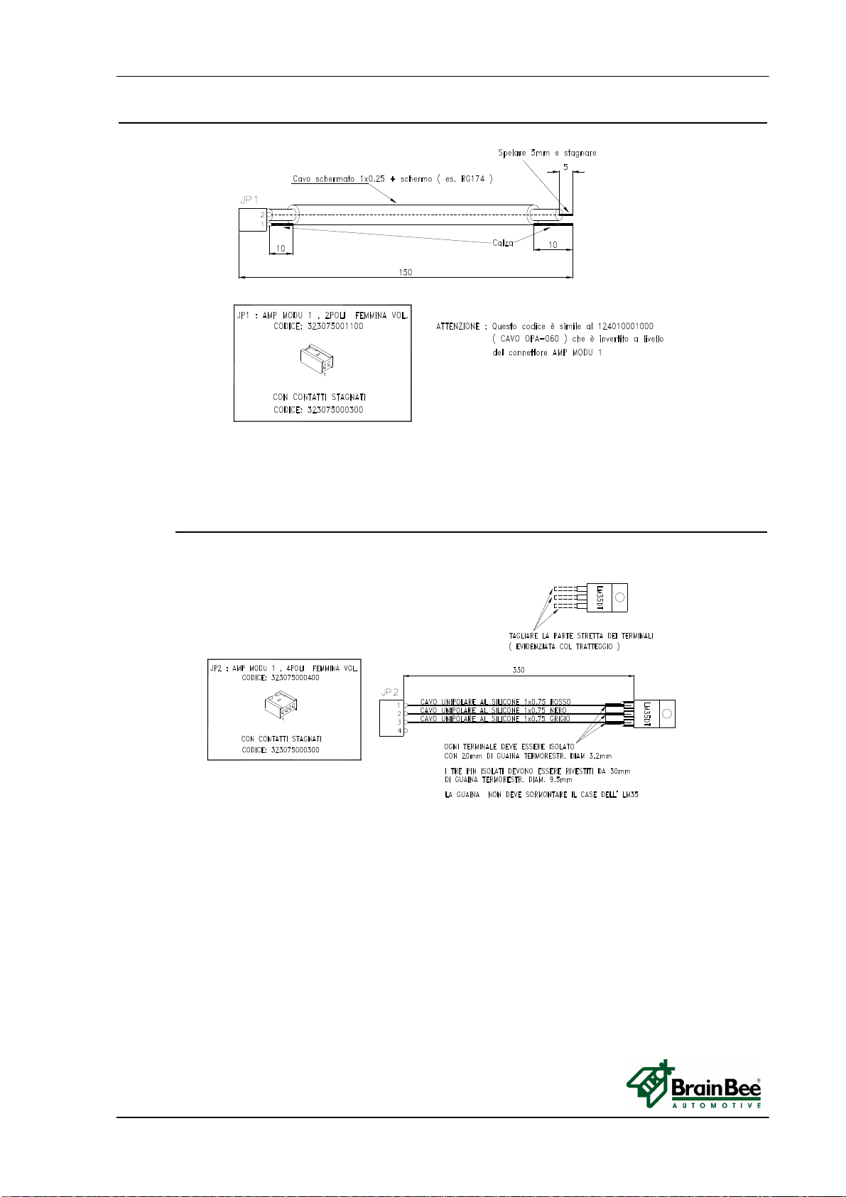
4.2.8 124010001100 Cable for Photodiode Chamber light receiver
4.2.9 124010000900 Internal cable for LM35 Chamber temperature
OPA-100 TECHNICAL DOCUMENTS
MS0100-06-0_service_manual.doc 20/22 TECHNICAL DOCUMENTS
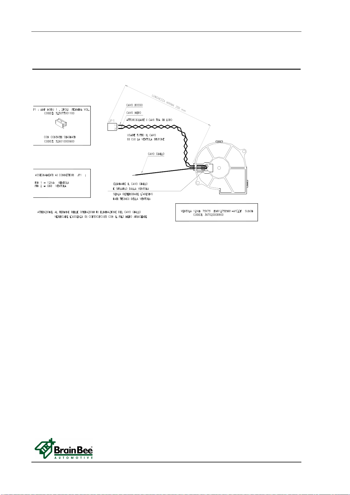
4.2.10 125010002400 Internal cable connected to Fan Side Emission Side
Receiver
Table of contents
Other Brain Bee Measuring Instrument manuals

Popular Measuring Instrument manuals by other brands

Image Engineering
Image Engineering TE292 user manual

Logitech Electronics
Logitech Electronics 2000 MKII Series user guide

Agilent Technologies
Agilent Technologies ENA Series Service guide

Baker Hughes
Baker Hughes Panametrics Sentinel LCT8 user manual

Banner
Banner A-GAGE EZ-ARRAY instruction manual

PCE Instruments
PCE Instruments Gossen ML 5052C USB operating instructions


