Brainboxes ED-549 User manual

Print Date: 28/03/17
Brainboxes Limited, 18 Hurricane Drive, Liverpool International Business Park, Speke, Liverpool, Merseyside, L24 8RL
Tel: +44 (0)151 220 2500 Fax: +44 (0)151 252 0446 Web: www.brainboxes.com Email: sale[email protected]om
Brainboxes Ethernet to Analogue IO

Ethernet Analogue DIO
Product Manual V1.3
© Copyright Brainboxes Ltd
Page 2 of 100
Contents
1 Introduction........................................................................................................................................................7
2Before you start ..................................................................................................................................................8
Box Contents...........................................................................................................................................................8
Requirements .........................................................................................................................................................8
Supported Operating Systems............................................................................................................................8
System Requirements.........................................................................................................................................9
Network Requirements ......................................................................................................................................9
3Hardware Features ...........................................................................................................................................10
ED Range –Industrial............................................................................................................................................10
Usability Features .................................................................................................................................................11
Technical Specifications........................................................................................................................................11
Network connection .........................................................................................................................................11
Power................................................................................................................................................................11
Storage and Operating Environment Guidelines ..................................................................................................12
LED indicators ...................................................................................................................................................12
Block Diagrams .....................................................................................................................................................13
ED-549 ..............................................................................................................................................................13
ED-560 ..............................................................................................................................................................13
Pin-outs.................................................................................................................................................................14
Device Dimensions................................................................................................................................................15
ED-549 ..............................................................................................................................................................15
ED-560 ..............................................................................................................................................................15
Reset Button .........................................................................................................................................................16
Manual Reboot .................................................................................................................................................16
Manual Hard Restore........................................................................................................................................16
Specification .........................................................................................................................................................17
ED-549 Input Specification ...............................................................................................................................17
ED-560 Output Specification ............................................................................................................................18
Firewall Exceptions and Port Numbers.................................................................................................................18
4Getting Started .................................................................................................................................................19

Ethernet Analogue DIO
Product Manual V1.3
© Copyright Brainboxes Ltd
Page 3 of 100
Connecting your ED device ...................................................................................................................................19
Configuring your device settings ..........................................................................................................................19
Connecting analogue signal sources to the ED-549..............................................................................................20
Differential (balanced) voltage signal ...............................................................................................................20
Single-ended (unbalanced) voltage signal ........................................................................................................20
Current-loop transducer signal.........................................................................................................................20
Current-sink transducer signal..........................................................................................................................21
Current-source transducer signal .....................................................................................................................21
Connecting analogue devices to the ED-560 ........................................................................................................22
Single-ended voltage signal ..............................................................................................................................22
Current-loop signal ...........................................................................................................................................22
5Boost.IO Manager.............................................................................................................................................23
Introduction..........................................................................................................................................................23
Installing Boost.IO Manager .................................................................................................................................23
Finding and Installing an ED device ......................................................................................................................24
COM Port Settings ................................................................................................................................................26
Advanced COM Port Settings............................................................................................................................28
TCP/IP Settings..................................................................................................................................................29
Adding a Device by IP Address..............................................................................................................................29
Adding a Device by MAC Address.........................................................................................................................31
IP Addressing ........................................................................................................................................................32
Rebooting Device..................................................................................................................................................33
Restoring Factory Settings ....................................................................................................................................34
Firmware Upgrade ................................................................................................................................................34
Proxy Server Settings ............................................................................................................................................36
Device Swapping...................................................................................................................................................36
Adding a Remote Device Using Boost.IO ..............................................................................................................36
Remote Access......................................................................................................................................................37
6Web Configuration Pages .................................................................................................................................38
Introduction..........................................................................................................................................................38
Home page............................................................................................................................................................38

Ethernet Analogue DIO
Product Manual V1.3
© Copyright Brainboxes Ltd
Page 4 of 100
Network page .......................................................................................................................................................41
Protocol page........................................................................................................................................................42
ASCII Protocol Settings .....................................................................................................................................43
Serial Expansion Settings ..................................................................................................................................44
Modbus TCP Settings........................................................................................................................................44
Console page ........................................................................................................................................................46
I/O Lines page .......................................................................................................................................................47
Input I/O Lines page (ED-549)...........................................................................................................................47
Output I/O Lines page (ED-560)........................................................................................................................50
Device Management page....................................................................................................................................51
Factory Default Settings........................................................................................................................................52
7ASCII Protocol ...................................................................................................................................................53
Introduction..........................................................................................................................................................53
Command Format.................................................................................................................................................53
Response Format ..................................................................................................................................................54
Range settings and data formats ..........................................................................................................................55
ED-549 Analogue input type settings (rr) .........................................................................................................55
ED-560 Analogue input type settings (tt) .........................................................................................................56
Command List .......................................................................................................................................................56
Baud Rate Settings (cc) .....................................................................................................................................57
Data Format Settings (ff) ..................................................................................................................................57
%aannttccff...........................................................................................................................................................58
#** ........................................................................................................................................................................59
#aa ........................................................................................................................................................................60
#aan ......................................................................................................................................................................61
#aan(Data) ............................................................................................................................................................62
$aa0Ci ...................................................................................................................................................................63
$aa1Ci ...................................................................................................................................................................64
$aa2 ......................................................................................................................................................................65
$aa4 ......................................................................................................................................................................66
$aa5vv...................................................................................................................................................................67

Ethernet Analogue DIO
Product Manual V1.3
© Copyright Brainboxes Ltd
Page 5 of 100
$aa6 ......................................................................................................................................................................68
$aa7CiRrr ..............................................................................................................................................................69
$aa8Ci ...................................................................................................................................................................70
$aa9nttss ..............................................................................................................................................................71
$aa9nts .................................................................................................................................................................72
$aa9n ....................................................................................................................................................................73
$aaA......................................................................................................................................................................74
$aaB ......................................................................................................................................................................75
$aaF ......................................................................................................................................................................76
$aaM.....................................................................................................................................................................77
$aaM0...................................................................................................................................................................78
$aaM1...................................................................................................................................................................79
$aaRS ....................................................................................................................................................................80
$aaS0 ....................................................................................................................................................................81
$aaS1 ....................................................................................................................................................................82
~aaEv.....................................................................................................................................................................83
~aaL(Location) ......................................................................................................................................................84
~aaO(Name)..........................................................................................................................................................85
~** ........................................................................................................................................................................86
~aa0 ......................................................................................................................................................................87
~aa1 ......................................................................................................................................................................88
~aa2 ......................................................................................................................................................................89
~aa3ett..................................................................................................................................................................90
~aa4n ....................................................................................................................................................................91
~aa5n ....................................................................................................................................................................92
8Modbus TCP Protocol .......................................................................................................................................93
Introduction..........................................................................................................................................................93
Slave ID .................................................................................................................................................................93
Addressing notations............................................................................................................................................93
Logical addressing.............................................................................................................................................94
984 style addressing .........................................................................................................................................94

Ethernet Analogue DIO
Product Manual V1.3
© Copyright Brainboxes Ltd
Page 6 of 100
IEC 61131 addressing........................................................................................................................................94
Modbus 1.1b3 standard addressing .................................................................................................................95
Product data tables and value encoding ..............................................................................................................95
ED-549 ..............................................................................................................................................................95
ED-560 ..............................................................................................................................................................97
9Lifetime Warranty and Support........................................................................................................................98
10 Regulatory Approvals / Compliance .................................................................................................................98
Company Accreditation ........................................................................................................................................98
Europe –EU Declaration of Conformity ...............................................................................................................99
WEEE Directive (Waste Electrical and Electronic Equipment)..............................................................................99
RoHS Compliance.................................................................................................................................................99
11 Copyright ........................................................................................................................................................100

Ethernet Analogue DIO
Product Manual V1.3
© Copyright Brainboxes Ltd
Page 7 of 100
1Introduction
The Brainboxes Ethernet to Analogue products are a range of Ethernet devices controlled by a host computer
which provide analogue inputs and outputs for high-precision measuring and control of voltages and currents.
The ED-549 has 8 analogue inputs which are independently configurable as differential voltage inputs or
current inputs, and the ED-560 has 4 analogue outputs which are independently configurable as voltage or
current outputs.
The ED range is designed and built on-site at the company’s headquarters in Liverpool, England, with close
collaboration between the hardware and software teams to deliver a product that is both user-friendly and
has plenty of functionality.
Ethernet Analogue DIO
Product Manual V1.3
© Copyright Brainboxes Ltd
Page 8 of 100
2Before you start
Box Contents
The following items are included with your Ethernet Analogue Input/Output Device product:
Boost.IO Installation CD including manual, Microsoft signed drivers and utilities
Quick Start Guide
Optional Items:
PW-600: Power Adapter 5V 1A Terminal Tails UK/EU/US/AUS
PW-650: USB to 5 Pin Terminal Block Power Adapter. Ideal for powering your ED device from
anywhere using your laptop
If any of the items are missing from your box or damaged in any way please contact support@brainboxes.com
Requirements
Supported Operating Systems
The Ethernet to Analogue product range can be used in the following Microsoft Operating Systems with the
supplied Boost.IO drivers:
Windows Server 2012
Windows 8.1 32-bit
Windows 8.1 64-bit
Windows 8 32-bit
Windows 8 64-bit
Windows 2008 R2
Windows 7 32-bit
Windows 7 64-bit
Windows Server 2008 32-bit
Windows Server 2008 64-bit
Windows Vista 32-bit
Windows Vista 64-bit
Windows Server 2003 32-bit
Windows Server 2003 64-bit
Windows XP 32-bit
Windows XP 64-bit
Windows 2000

Ethernet Analogue DIO
Product Manual V1.3
© Copyright Brainboxes Ltd
Page 9 of 100
Brainboxes Boost.IO drivers have undergone extensive Microsoft testing with the ED range. Upon passing
these tests, the drivers were signed by Microsoft, as an indication of their quality and stability.
System Requirements
Components: Microsoft .NET Framework 2.0 (installed automatically with Boost.IO package)
Windows Installer: Windows Installer 3.1 or later (Recommended)
Internet Explorer: If you are running Internet Explorer, then Internet Explorer 7.0 or later is required
Processor: 400 MHz Pentium processor or equivalent (Minimum); 1GHz Pentium processor or equivalent
(Recommended)
RAM: 96 MB (Minimum); 256 MB (Recommended)
Hard Disk: Up to 500 MB of available space may be required
CD or DVD Drive: Not required
Display: 800 x 600, 256 colours (Minimum); 1024 x 768 high colour, 32-bit (Recommended)
Network Requirements
Ethernet network connection (10BaseT/100BaseTX).

Ethernet Analogue DIO
Product Manual V1.3
© Copyright Brainboxes Ltd
Page 10 of 100
3Hardware Features
ED Range –Industrial

Ethernet Analogue DIO
Product Manual V1.3
© Copyright Brainboxes Ltd
Page 11 of 100
Usability Features
The ED range has been designed so that it is as easy as possible to wire up the input/output, serial expansion
and power wires to the terminal blocks and to connect the network cable:
Removable screw terminal blocks make installation easier and quicker.
Colour coded terminal blocks and ports prevent an incorrect connection.
Individually numbered pins simplify the wiring and removes confusion.
Smart Ethernet which automatically detects the polarity of the Ethernet connection so either a
straight through or crossover Ethernet cable can be used.
Built-in functional ground connection to DIN rail.
Power input from 5-30V: dual redundant input enables two power sources to be connected
Can use the 5 Volt power from any computer USB port via the optional cable accessory PW-650.
Technical Specifications
Network connection
-10Base-T or 100Base-TX Ethernet connection
-Standard 8P8C (“RJ45”) socket connector
-TCP/IP protocol stack
-DHCP or static IP address
-Automatic transmit/receive crossover detection
-1500V magnetic isolation
Power
-Wide-range +5 to +30V DC 60mA@24V 1.4W Typical 120mA@24V 2.9W Max
-Reverse voltage protected
-ESD and surge protected
-Earthing connection point
!
Caution - Do not attempt to operate this product with
any other power supply/rating than that specified.

Ethernet Analogue DIO
Product Manual V1.3
© Copyright Brainboxes Ltd
Page 12 of 100
Storage and Operating Environment Guidelines
ED Range –Industrial
Operating Temperature:
-30°C to +80°C
Storage Temperature:
-40°C to +85°C
Humidity:
5% to 95% non-condensing
Housing:
IP 20 rated non-conducting polyamide case
Integrated DIN rail mount
LED indicators
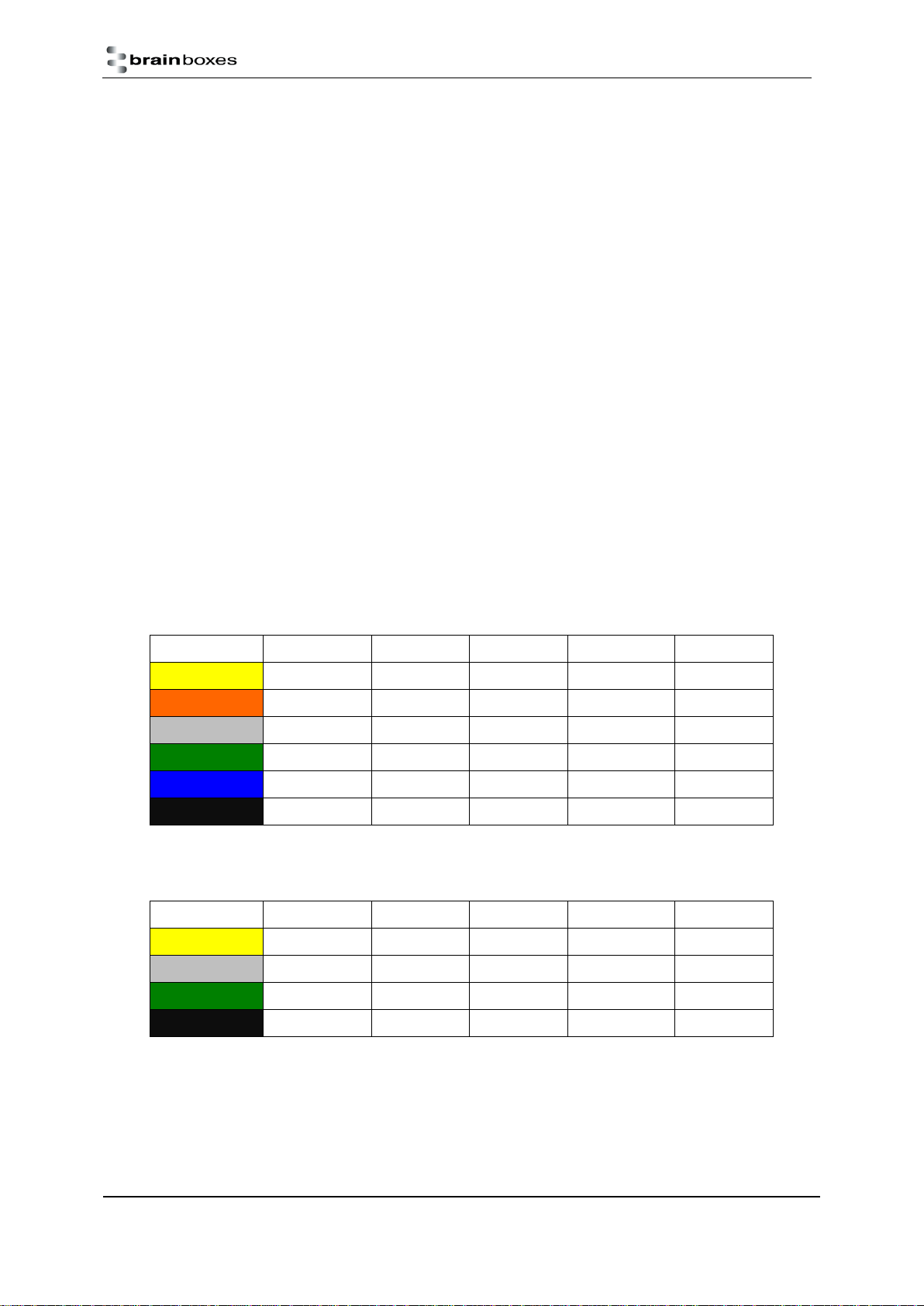
There are 4 LEDs on the ED devices representing the status, expansion port, Ethernet link and the activity. The
table below lists these LEDs and the meaning of the colours.
Status LED
Green
Device Ready
Flashing Yellow
Changing Settings
Flashing between Red & Green
Querying IP
Flashing Green and Red
User performing Hard Reset
Flashing between Green & Red/Yellow
IP address diagnostic
Flashing between Green & Yellow
Initialization diagnostic
Expansion
Flashing Red
RS-485 Comms error
Flashing Green
RS-485
Link LED
Green light on
Network Link Established
Flashing Green
Network Data RX/TX
Activity
Flashing Green
Input Read
Flashing Red
Input Error

Ethernet Analogue DIO
Product Manual V1.3
© Copyright Brainboxes Ltd
Page 13 of 100
Block Diagrams
ED-549
ED-560
Ethernet Analogue DIO
Product Manual V1.3
© Copyright Brainboxes Ltd
Page 14 of 100
Pin-outs
Functional Ground is a ground connection for the reduction of electrical noise. It is different from a
Protective Earth which is for safety purposes, and is not required on these products due to their low operating
voltage. The Functional Ground (earth) on the ED-5xx product series is on pin 5 of the black power connector.
There is also a contact clip on the back of the product case which connects the Functional Ground to the DIN
rail the product is mounted on. DIN rails are typically grounded, in which case it is not necessary to wire to the
Functional Ground terminal as well.
Power Ground (GND, -V) is the low side or “0V”of the power input. The terminals labelled GND on the pin-
out tables are connected directly to the –V terminals of the BLACK power input connector and are thus
connected to the low side of the power supply/supplies.
Analogue Ground (AGND) is the ground for the analogue input or output circuitry. It is isolated from
power ground to reduce noise and prevent ground loops, but can be connected to power ground if the system
design requires it. For the ED-560, AGND is the reference voltage for the single-ended voltage outputs and the
loop 0V terminal for current-mode outputs. For the ED-549, the analogue measurements are not directly
dependent on the AGND connection (voltage mode measures the voltage between the AIn+ and the AIn-
terminals, and current mode measures the current flowing through the AIn+ and AIn- terminals) –but AGND is
still required to be connected to a suitable 0V point on the signal-sourcing equipment, such that all the AIn+
and AIn- terminals are within ±11V of AGND. AGND is also a suitable connection point for any cable shield or
drain wires.
ED-549 Pin-outs
Terminal Block
Pin 1
Pin 2
Pin 3
Pin 4
Pin 5
Yellow
AGND
AIn 0-
AIn 0+
AIn 1-
AIn 1+
Orange
AGND
AIn 2-
AIn 2+
AIn 3-
AIn 3+
Grey
GND
RS-485 D-
RS-485 D+
RS-485 D+
RS-485 D-
Green
AGND
AIn 4-
AIn 4+
AIn 5-
AIn 5+
Blue
AGND
AIn 6-
AIn 6+
AIn 7-
AIn 7+
Black
-V
+VA
+VB
-V
Func GND
ED-560 Pin-outs
Terminal Block
Pin 1
Pin 2
Pin 3
Pin 4
Pin 5
Yellow
AGND
VOut 0
VOut 1
IOut 0
IOut 1
Grey
GND
RS-485 D-
RS-485 D+
RS-485 D+
RS-485 D-
Green
AGND
VOut 2
VOut 3
IOut 2
IOut 3
Black
-V
+VA
+VB
-V
Func GND
Ethernet Analogue DIO
Product Manual V1.3
© Copyright Brainboxes Ltd
Page 15 of 100
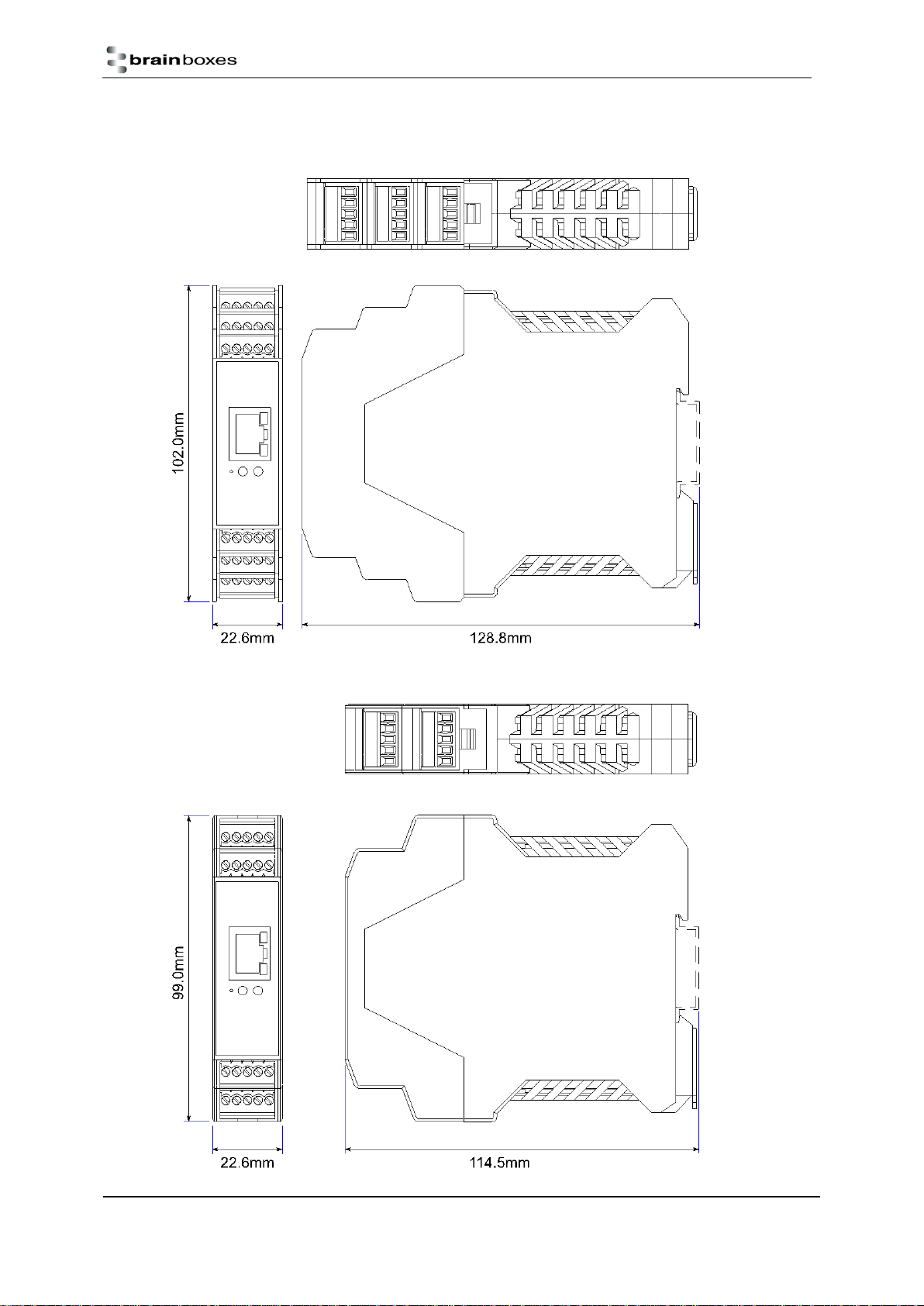
Device Dimensions
ED-549
ED-560

Ethernet Analogue DIO
Product Manual V1.3
© Copyright Brainboxes Ltd
Page 16 of 100
Reset Button
The reset button is behind the hole marked ‘Reset’ on the front panel. To press it, use a straightened-out
paper clip or similar tool.
Manual Reboot
1) Press the reset button once.
2) The status LED will flash and after 5 seconds the device will reboot.
3) When the device is restarted, any connections you have had to the COM ports will need to be re-
established.
Manual Hard Restore
1) Press and hold the reset button on the device for 5 seconds.
2) The status LED will flash red/green and the device will be restored to factory default settings. For the
factory settings, see Factory Default Settings section. Any user calibration will be erased, and the
calibration will return to the factory calibration as originally supplied to you.
Ethernet Analogue DIO
Product Manual V1.3
© Copyright Brainboxes Ltd
Page 17 of 100
Specification
ED-549 Input Specification
The ED-549 provides eight analogue input channels, each of which is independently configurable as either a
differential voltage input or a current-sense input.
In voltage input mode, the input impedance is a minimum or 10MΩ. The full scale range can be configured as
±10V, ±5V, ±2.5V, ±1V, ±500mV, ±250mV, ±150mV or ±75mV using either an ASCII command or by selecting
the range on the web configuration pages.
In current input mode, a 115Ω sense resistor is used. The full scale range can be set to either ±20mA, 0-20mA
or 4-20mA.
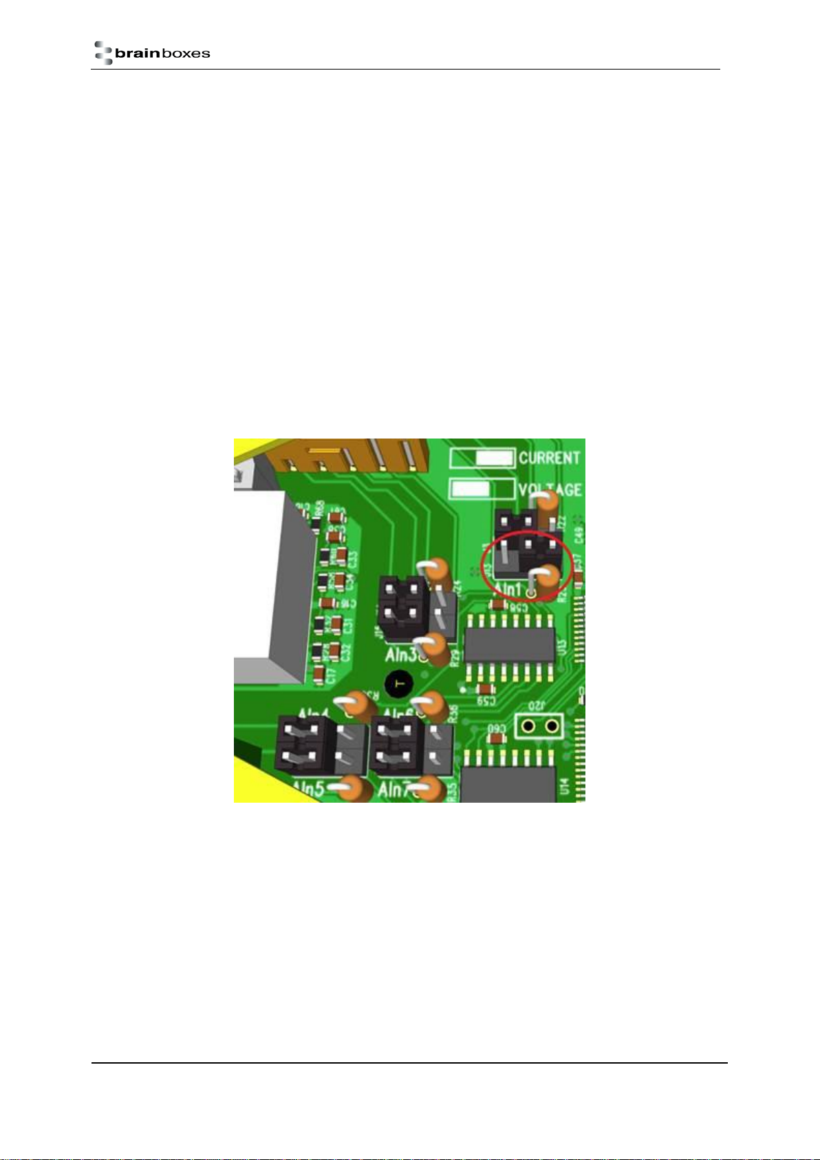
Each channel has a jumper block that allows it to be individually set for either voltage input mode or current
input mode. The factory fitted configuration is that all 8 channels are set to voltage input mode. When the
jumper is across the left hand and central pins the channel has a high input impedance suitable for voltage
input ranges; when the jumper is across the right hand and central pins the channel has a 115Ω sense resistor
enabled suitable for current input ranges. In the picture AIn1 is set for current measurements, all other
channels are set for voltage measurements.
The device can make 12 measurements per second, divided between all the enabled inputs, and reports the
measurements with 16-bit resolution.
The allowed single-ended voltage of any analogue input pin is within ±11V of the AGND pins.
Measurement accuracy for the inputs on the device is within 0.1% of the full scale range at 25°C and 0.3% of
the full scale range over -30°C to +80°C. The common-mode rejection ratio (CMRR) of the analogue inputs is
over 120dB and the normal-mode rejection ratio (NMRR) of the inputs is greater than 100dB at both 50Hz and
60Hz.
Ethernet Analogue DIO
Product Manual V1.3
© Copyright Brainboxes Ltd
Page 18 of 100
ED-560 Output Specification
The device provides four analogue output channels, each of which has a voltage output terminal and a current
output terminal. Each analogue output channel is independently configurable by software for a calibrated 0-
10V voltage output, a 0-20mA current output or a 4-20mA current output. When an output channel is
configured for voltage output then the state of the current output signal is undefined; when an output channel
is configured for current output then the state of the voltage output signal is undefined.
The voltage outputs generate voltages within 10mV of the software-programmed value (0.1% of the full-scale
range), while sourcing between -5mA and 5mA. The temperature drift of the zero output is no larger than
30µV/°C, and the temperature drift of the span is no larger than 25ppm/°C.
The current output is of the ‘sink’ type, and requires an external power source. The voltage of the power
source needs to be sufficient to provide at least 2.8V at the IOut terminal, up to a maximum of 30V. The
outputs sink a current within 16µA of the software-programmed value (0.1% of the full-scale range). The
temperature drift of the zero output is no larger than 0.2µA/°C, and the temperature drift of the span is no
larger than 25ppm/°C.
The settling time for output signals will depend on the load on the outputs, but in tests with an oscilloscope
probe as the load the voltage output took around 350µs to settle when moving between 1V and 9V, and the
current output took around 4µs to settle when moving between 2mA and 18mA.
Firewall Exceptions and Port Numbers
When using the ED Devices with a firewall you may need to manually add the exception entries and port
numbers to the firewall list.
Below are the default port numbers and the firewall exceptions.
Function
Default port number
Device web server
TCP port 80
ASCII protocol
TCP port 9500
Modbus protocol
TCP port 502
Firmware upgrade
UCP ports 67, 68, 69
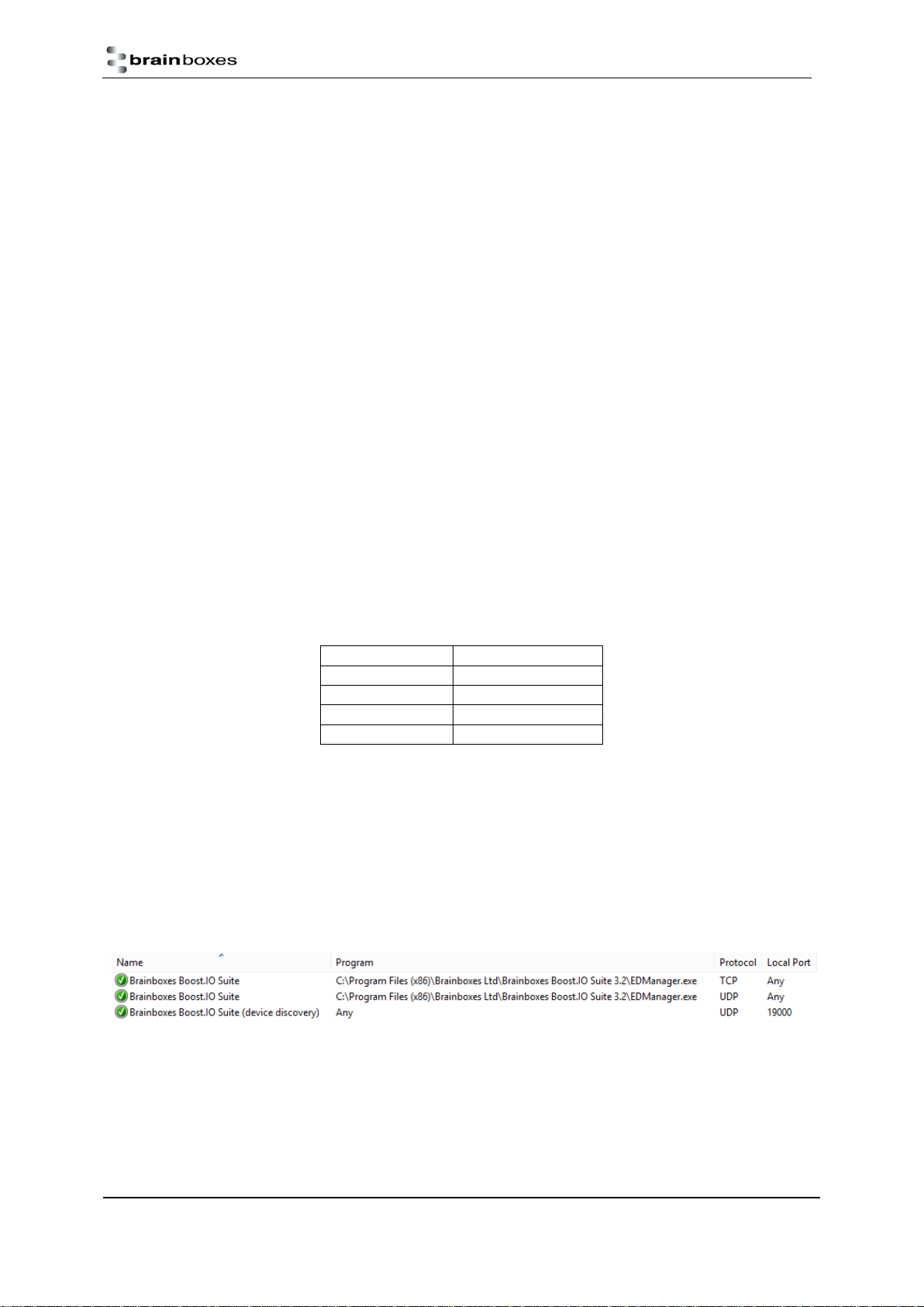
Below are listed the Windows Firewall exception entries which are added by default during the installation of
Boost.IO Manager.
Brainboxes Boost.IO Suite
Brainboxes Boost.IO Suite (Device Discovery)
(Except Windows XP32 & 64 bits)
UPnP Framework (Windows XP32 & 64 bits)
Network Discovery (Windows 7 or later)
If you are using other anti-virus or firewall software you may need to add these exceptions into the anti-virus
and firewalls you have installed.

Ethernet Analogue DIO
Product Manual V1.3
© Copyright Brainboxes Ltd
Page 19 of 100
4Getting Started
Connecting your ED device
1. Connect a power supply providing a minimum of 1.1 Watts with an output voltage between +5VDC
and +30VDC to the removable black terminal block. The optional PW-600 and PW-650 power supplies
enable the device to be plugged easily into a standard power socket or powered via USB.
a. Using one power supply: connect the positive terminal of the power supply to either +VA or
+VB pin and the negative to one of the -V pins.
b. Using two separate power supplies: connect one to +VA and -V and the other to +VB and -V.
The higher voltage of the two power supplies is selected by the device and in the event of a
failure the other supply automatically takes over to keep the device running. The status of
the power supply inputs can be monitored visually via a browser from the ED devices home
page and also programmatically.
Terminal Block
Pin 1
Pin 2
Pin 3
Pin 4
Pin 5
Black
-V
+VA
+VB
-V
Func GND
2. Connect the ED device to your local network by plugging an Ethernet cable into the Ethernet port on
the device. The ED Ethernet port will automatically detect the polarity of the Ethernet connection so
either straight-through or crossover Ethernet cables can be used.
3. The LEDs will flash when the power is first applied. When the status LED turns a steady green (after 5-
60 seconds) the device is ready to use.
4. On connecting to the network, the device automatically checks if it there is a DHCP server available. If
this is the case, the DHCP server will allocate an IP address automatically to the ED device.
5. If no DHCP server is detected (e.g. you have the ED device plugged directly into the PC), the ED device
will default to an IP address of 192.168.127.254 after 60 seconds. If connecting directly to a PC, make
sure the PC is on the same 192.168.127.xxx subnet in order to find your device.
Make a note of device MAC address (on the side of the ED device, 00-0A-4F-XX-XX) as you will need it
to identify the device on your network later.
Configuring your device settings
There are three methods to view and configure your ED device. Which method to use depends on personal
preference and convenience.
Boost.IO Manager: This is the Windows application that is installed initially to find the device and
install the COM port drivers if required. Configuring from here is the recommended option for ease
and convenience, as it centralises all Ethernet to Analogue devices in one window. However, not all
of the settings of the ED device can be configured from the Boost.IO Manager. See Section 5 for
information about Boost.IO Manager.
Web Page Interface: This allows the Ethernet to Analogue device to be accessed from any PC within
your network as it does not require Boost.IO Manager. Unlike Boost.IO Manager, every setting can be
configured using the web configuration pages. See Section 6 for more information about the web
page interface.
ASCII Protocol: The ASCII protocol is a query-response communication protocol which can be used to
set all of the protocol settings of the device, send and read data, and get status information from the

Ethernet Analogue DIO
Product Manual V1.3
© Copyright Brainboxes Ltd
Page 20 of 100
devices. To send the commands and receive responses a connection to the device needs to be set up.
This can be done using either a TCP connection or through the COM port.
Modbus TCP Protocol: Modbus TCP is a standard communication protocol which can also be used to
read and write configuration and analogue value data. It uses binary data instead of human-readable
ASCII text, and is supported by a wide range of PLCs and data acquisition software. Unlike the ASCII
protocol, it allows overlapping requests and connections from multiple controllers.
Connecting analogue signal sources to the ED-549
These are not the only ways in which the products may usefully be connected, but the diagrams below show
the most common configurations.
Differential (balanced) voltage signal
Single-ended (unbalanced) voltage signal
Current-loop transducer signal
This manual suits for next models
1
Table of contents
Other Brainboxes Media Converter manuals


