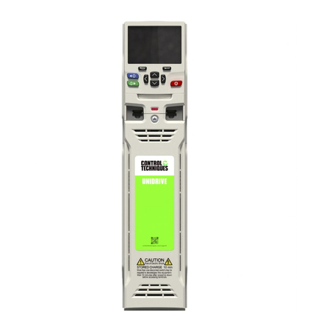
Control Techniques Unidrive M201 User manual

Control Quick Start
Guide
Unidrive M200/201
Part Number: 0478-0282-03
Issue: 3
Flexible machine integration
through communications

Original Instructions
For the purposes of compliance with the EU Machinery Directive 2006/42/EC
This guide is intended to provide basic information required in order to set-up a drive to run a motor.
For more detailed installation information, please refer to the relevant drive documentation which is
available to download from:
www.drive-setup.com
Warnings, Cautions and Notes
Copyright © April 2017
Issue Number: 3
A Warning contains information which is essential for avoiding a safety hazard.
A Caution contains information which is necessary for avoiding a risk of damage to the
product or other equipment.
A Note contains information, which helps to ensure correct operation of the product.
This guide does not include safety information. Incorrect installation or operation of the
drive, could cause personnel injury or equipment damage. For essential safety
information, please refer to the relevant drive documentation or the safety booklet supplied
with the drive.
WARNING
CAUT IO N
NOTE
WARNING

Unidrive M200/201 Control Quick Start Guide
Issue Number: 3
Contents
1 Safety information ....................................................................................... 4
1.1 Warnings, Cautions and Notes ................................................................................ 4
1.2 Installation and Use ................................................................................................. 4
1.3 Enclosure ................................................................................................................. 4
1.4 Competence of the installer ..................................................................................... 4
1.5 Electric Shock and Fire Hazards ............................................................................. 5
1.6 Electrical installation ................................................................................................ 5
1.7 Setting up, commissioning and maintenance .......................................................... 6
1.8 Safety of machinery, safety-critical applications ...................................................... 6
1.9 Electromagnetic compatibility (EMC) ....................................................................... 7
1.10 Copyright ................................................................................................................. 7
2 Introduction ..................................................................................................8
2.1 Operating modes ..................................................................................................... 8
3 Options .........................................................................................................9
4 Control connections ..................................................................................10
4.1 Control terminal configurations and wiring ............................................................. 10
5 Keypad and display ...................................................................................16
5.1 Saving parameters ................................................................................................ 17
5.2 Restoring parameter defaults ................................................................................ 17
6 Basic parameters (Menu 0) .......................................................................18
6.1 Menu 0: Basic parameters ..................................................................................... 18
6.2 Unidrive M200/201 parameter descriptions ........................................................... 24
7 Running the motor .................................................................................... 46
8 Diagnostics ................................................................................................48
8.1 Alarm indications ................................................................................................... 52
9 NV Media Card Operation .........................................................................53
10 Machine Control Studio ............................................................................54

4Unidrive M200/201 Control Quick Start Guide
Issue Number: 3
1 Safety information
1.1 Warnings, Cautions and Notes
1.2 Installation and Use
The information given in this publication is derived from tests and calculations on sample products. It
is provided to assist in the correct application of the product, and is believed to correctly reflect the
behaviour of the product when operated in accordance with the instructions. The provision of this
data does not form part of any contract or undertaking. Where a statement of conformity is made with
a specific standard, the manufacturer takes all reasonable measures to ensure that its products are
in conformance. Where specific values are given these are subject to normal engineering variations
between samples of the same product. They may also be affected by the operating environment and
details of the installation arrangement.
The manufacturer accepts no liability for any consequences resulting from inappropriate, negligent or
incorrect installation of the equipment.
1.3 Enclosure
Unless stated otherwise in the installation instructions, the product is intended to be mounted in an
enclosure which prevents access except by trained and authorized personnel, and which prevents
the ingress of contamination. It is designed for use in an environment classified as pollution degree 2
in accordance with IEC 60664-1. This means that only dry, non-conducting contamination is
acceptable.
1.4 Competence of the installer
Installation should be carried out by professional installers who are familiar with the requirements for
safety and EMC. The installer is responsible for ensuring that the end product or system complies
with all the relevant laws in the country where it is to be used.
A Warning contains information which is essential for avoiding a safety hazard.
A Caution contains information which is necessary for avoiding a risk of damage to the
product or other equipment.
A Note contains information, which helps to ensure correct operation of the product.
WARNING - This warning applies to products intended to be used with variable
speed drives.
The adjustable speed drive uses high voltages and currents, carries a high level of stored
electrical energy, and is used to control mechanical plant which can cause injury.
Close attention is required to the electrical installation and the system design to avoid
hazards either in normal operation or in the event of equipment malfunction.
System design, installation, commissioning and maintenance must be carried out by
personnel who have the necessary training and experience. They must read this safety
information and the instruction manual carefully.
Failure to observe the following instructions can cause physical injury or death, or damage
to the equipment.
WARNING
CAUT IO N
NOTE
WARNING

Unidrive M200/201 Control Quick Start Guide 5
Issue Number: 3
1.5 Electric Shock and Fire Hazards
1.5.1 AC supply
The AC supply must be isolated before any servicing work is performed, other than adjustments to
the settings or parameters specified in the manual.
1.5.2 Live terminals
Some types of signal and control lines carry hazardous voltages (120/ 240 V) and can cause severe
electric shock and may be lethal.
1.5.3 Stored charge
Some products contain capacitors that remain charged to a potentially lethal voltage after the power
supply has been disconnected. It is recommended that the power supply is isolated at least ten
minutes before working on the equipment.
1.6 Electrical installation
1.6.1 Protective Ground (Earth) connection
The ground loop impedance must conform to the requirements of local safety regulations. The
equipment must be grounded by a connection capable of carrying the prospective fault current until
the protective device (fuse or circuit breaker) disconnects the supply. The ground connections must
be inspected and tested at appropriate intervals.
1.6.2 Fuses
The supply to the equipment must be installed with suitable protection against overload and short-
circuits. The tables in the relevant documentation show recommended fuse ratings. Failure to
observe these installation instructions could result in fire.
1.6.3 Cables
The cable sizes in the relevant documentation are only a guide. The mounting and grouping of
cables affects their current-carrying capacity, in some cases smaller cables may be acceptable but in
other cases a larger cable is required to avoid excessive temperature or voltage drop. Refer to local
wiring regulations for the correct size of cables. Failure to observe these installation instructions
could result in fire.
1.6.4 Terminal connections and torque settings
Loose power connections can be a fire risk. Always ensure that terminals are tightened to the
specified torques. Refer to the tables in the relevant documentation.
1.6.5 High voltage insulation (flash) testing
High voltage insulation (flash) testing should not be carried out on the equipment.
1.6.6 ELV terminals
The ELV terminals are insulated from the mains supply by a single isolation barrier.
These terminals must be prevented from human contact by an additional isolation barrier, for
example a terminal cover.
WARNING - Dangerous voltage
Where products are supplied by or connected to mains voltages, the voltages used can
cause severe electrical shock and/or burns, and could be lethal. Extreme care is
necessary at all times when working with or adjacent to the equipment. Refer to the
relevant documentation.
WARNING

6Unidrive M200/201 Control Quick Start Guide
Issue Number: 3
1.6.7 SELV terminals
SELV terminals can be safely connected to other SELV equipment and further protection against
human contact is not required.
If an ELV terminal is connected directly to a SELV circuit (on the drive or other equipment), the
combined circuit is ELV.
For this reason, ELV terminals should not be connected to SELV circuits unless it is acceptable to
compromise the SELV circuit.
1.6.8 Products connected by plug and socket
An electric shock hazard exists if mains-supplied equipment is supplied via a plug and socket. When
unplugged, the pins of the plug may carry a potentially lethal voltage until the internal capacitors have
discharged. This can take up to 10 minutes.
It is recommended that a shrouded plug is used that prevents contact with the pins.
1.7 Setting up, commissioning and maintenance
1.7.1 Lifting and handling
Some items of equipment weigh in excess of 15 kg (33 lb). Use appropriate safeguards when lifting
these models. A full list of weights can be found in the installation instructions.
1.7.2 Output circuit and motor protection
Control parameters that are related to motor overload and protection must be set correctly to avoid a
risk of overheating and fire in the event of motor overload. In some applications motor temperature
protection may also be required.
1.7.3 STOP, Enable and Safe Torque Off functions (where applicable)
These functions do not remove dangerous voltages from the equipment or any external option unit,
nor do they isolate the motor from dangerous voltages.
Automatic start
Some parameter settings may cause the motor to start unexpectedly.
Restore default parameter set
Depending on the application, this may cause unpredictable or hazardous operation.
1.8 Safety of machinery, safety-critical applications
Within the European Union all machinery in which this product is used must comply with Machinery
Directive 2006/42/EC.
The design of safety-related control systems must only be done by personnel with the required
training and experience. The Safe Torque Off function will only ensure the safety of a machine if it is
correctly incorporated into a complete safety system. The system must be subject to a risk
assessment to confirm that the residual risk of an unsafe event is at an acceptable level for the
application.
It is essential that changes to the settings are given careful consideration. Depending on
the application, a change could have an impact on safety. Appropriate precautions must
be taken against inadvertent changes or tampering. Some specific settings which require
particular care are listed below. This is not an exclusive list. Other settings may have an
impact on safety in specific applications.
CAUTION

Unidrive M200/201 Control Quick Start Guide 7
Issue Number: 3
1.9 Electromagnetic compatibility (EMC)
The product is designed to comply with international standards in a typical installation. Installation
instructions are provided in the User Guide. If the installation is poorly designed or other equipment
does not comply with international standards for EMC, the product might cause or suffer from
disturbance due to electromagnetic interaction with other equipment. It is the responsibility of the
installer to ensure that the equipment or system into which the product is incorporated complies with
the relevant EMC legislation in the country of use.
Within the European Union, equipment into which this product is incorporated must comply with the
Electromagnetic Compatibility Directive 2014/30/EU.
1.10 Copyright
The contents of this publication are believed to be correct at the time of printing. In the interests of a
commitment to a policy of continuous development and improvement, the manufacturer reserves the
right to change the specification of the product or its performance, or the contents of the guide,
without notice.
All rights reserved. No parts of this publication may be reproduced or transmitted in any form by any
means, electrical or mechanical including photocopying, recording or by an information storage or
retrieval system, without permission in writing from the publisher

8Unidrive M200/201 Control Quick Start Guide
Issue Number: 3
2Introduction
Unidrive M200/M201 delivers substantial communications and application integration through
optional RS485 plus a wide range of industry standard fieldbus and I/O SI modules. Enhances
machine up-time and performance with it’s remote control monitoring.
2.1 Operating modes
The drive is designed to operate in any of the following modes:
1. Open loop mode
Open loop vector mode
Fixed V/F mode (V/Hz)
Square V/F mode (V/Hz)
2. RFC - A
Without position feedback sensor
2.1.1 Open loop mode
The drive applies power to the motor at frequencies varied by the user. The motor speed is a result of
the output frequency of the drive and slip due to the mechanical load. The drive can improve the
speed control of the motor by applying slip compensation. The performance at low speed depends
on whether V/F mode or open loop vector mode is selected.
Open loop vector mode
The voltage applied to the motor is directly proportional to the frequency except at low speed where
the drive uses motor parameters to apply the correct voltage to keep the flux constant under varying
load conditions.
Typically 100 % torque is available down to 1 Hz for a 50 Hz motor.
Fixed V/F mode
The voltage applied to the motor is directly proportional to the frequency except at low speed where a
voltage boost is provided which is set by the user. This mode can be used for multi-motor
applications.
Typically 100 % torque is available down to 4 Hz for a 50 Hz motor.
Square V/F mode
The voltage applied to the motor is directly proportional to the square of the frequency except at low
speed where a voltage boost is provided which is set by the user. This mode can be used for running
fan or pump applications with quadratic load characteristics or for multi-motor applications. This
mode is not suitable for applications requiring a high starting torque.
2.1.2 RFC-A mode
Rotor flux control provides closed loop control without the need for position feedback by using
current, voltages and key motor parameters to estimate the motor speed. It can eliminate instability
traditionally associated with open loop control such as operating large motors with light loads at low
frequencies.

Unidrive M200/201 Control Quick Start Guide 9
Issue Number: 3
3Options
Table 3-1 System Integration (SI) option module identification
Type Option module Color Name Further details
Fieldbus
Purple SI-PROFIBUS
See relevant option
module User Guide
Medium
Grey SI-DeviceNet
Light Grey SI-CANopen
Beige SI-Ethernet
Brown Red SI-EtherCAT
Yellow
Green SI-PROFINET V2
Automation
(I/O expansion) Orange SI-I/O

10 Unidrive M200/201 Control Quick Start Guide
Issue Number: 3
Table 3-2 Adaptor Interface (AI) option module identification
4 Control connections
For information on the default control connections, refer to the back cover of this guide. The
functionality of the control connections change depending on the setting of Pr 05.
4.1 Control terminal configurations and wiring
* With Unidrive M201, the default is PAd (5). The setting of Pr 05 automatically sets the drive
configuration.
Action will only occur if the drive is inactive and no User Actions are running. Otherwise, the
parameter will return to its pre altered value on exit from edit mode. All parameters are saved if this
parameter changes.
Type Option module Name
Communications
AI-485 Adaptor
AI-485 24V Adaptor
Backup AI-Backup Adaptor
Backup AI-SMART Adaptor
05 Drive Configuration
RW Txt PT US
OL
Ú
AV (0), AI (1), AV.Pr (2), AI.Pr (3),
PrESEt (4), PAd (5), PAd.rEF (6),
E.Pot (7), torquE (8), Pid (9)
ÖAV (0)*
RFC-A
Value Text Description
0AV
Analog input 1 (voltage) or Analog input 2 (voltage) selected by terminal
(Local/Remote)
1AI
Analog input 1 (current) or Analog input 2 (voltage) selected by terminal
(Local/Remote)
2AV.Pr
Analog input 1 (voltage) or 3 presets selected by terminal
3 AI.Pr Analog input 1 (current) or 3 presets selected by terminal
4PrESEt
Four presets selected by terminal
5PAd
Keypad reference
6 PAd.rEF Keypad reference with terminal control
7E.Pot
Electronic Potentiometer
8 torquE Torque mode, Analog input 1 (current frequency reference) or Analog input 2
(voltage torque reference) selected by terminal
9Pid
PID mode, Analog input 1 (current feedback source) and Analog input 2
(voltage reference source)

Unidrive M200/201 Control Quick Start Guide 11
Issue Number: 3
Figure 4-1 Pr 05 = AV
Figure 4-2 Pr 05 = AI
1
2
4
0V
Voltage speed reference
input (AI 2)
input (AI 1)
5
+ 10 V output
7
9
10
Digital output
(zero frequency)
Drive enable
11
12
13
14
Run reverse
Run forward
Analog output 1
(motor frequency)
Analog input 1/
input 2 select
+ 24 V output
10k
10k
1
2
4
0V
Current speed reference
Current speed
reference input
Voltage speed reference
input (AI 2)
input (AI 1)
5
+ 10 V output
7
9
10
Digital output
(zero frequency)
Drive enable
11
12
13
14
Run reverse
Run forward
Analog output 1
(motor frequency)
Analog input 1/
input 2 select
+ 24 V output
10k

12 Unidrive M200/201 Control Quick Start Guide
Issue Number: 3
Figure 4-3 Pr 05 = AV.Pr
Figure 4-4 Pr 05 = AI.Pr
* Refer to the Control User Guide.
1
2
4
0V
Voltage speed reference
Reference select
input (AI 1)
5
+ 10 V output
7
9
10 Digital output
(zero frequency)
Drive enable
11
12
13
14
Run reverse
Run forward
Analog output 1
(motor frequency)
Reference select
+ 24 V output
10k
Terminal 5 Terminal 14 Reference selected
0 0 Analog reference 1*
0 1 Preset speed 2*
1 0 Preset speed 3*
1 1 Preset speed 4*
1
2
4
0V
Current speed
reference input
Current speed
reference input (AI 1)
Reference select
Reference select
5
+ 10 V output
7
9
10 Digital output
(zero frequency)
Drive enable
11
12
13
14
Run reverse
Run forward
Analog output 1
(motor frequency)
+ 24 V output
Terminal 5 Terminal 14 Reference selected
0 0 Analog reference 1*
0 1 Preset speed 2*
1 0 Preset speed 3*
1 1 Preset speed 4*

Unidrive M200/201 Control Quick Start Guide 13
Issue Number: 3
Figure 4-5 Pr 05 = PrESEt
* Refer to the Control User Guide.
Figure 4-6 Pr 05 = PAd
Terminal 5 Terminal 14 Reference selected
0 0 Preset speed 1*
0 1 Preset speed 2*
1 0 Preset speed 3*
1 1 Preset speed 4*
1
2
4
0V
Voltage speed reference
Reference select
Reference select
input (AI 1)
5
+ 10 V output
7
9
10 Digital output
(zero frequency)
Drive enable
11
12
13
14
Run reverse
Run forward
Analog output 1
(motor frequency)
+ 24 V output
1
2
4
0V
Voltage speed reference
input (AI 2)
input (AI 1)
5
+10 Voutput
7
9
10 Digital output
(zero frequency)
Drive enable
11
12
13
14
Run reverse
Run forward
Analog output 1
(motor frequency)
Analog input 1/
input 2select
+24 Voutput
When Pr 05 is set to PAd, to run in reverse:
Set Pr 17 to On
The keypad reference can now be set to a
negative frequency to run the motor in the
reverse direction.

14 Unidrive M200/201 Control Quick Start Guide
Issue Number: 3
Figure 4-7 Pr 05 = PAd.rEF
Figure 4-8 Pr 05 = E.Pot
* Refer to the Control User Guide.
1
2
4
0V
Voltage speed reference
input (AI 2)
input (AI 1)
5
+ 10 V output
7
9
10 Digital output
(zero frequency)
Drive enable
11
12
13
14
Run reverse
Run forward
Analog output 1
(motor frequency)
Analog input 1/
input 2 select
+ 24 V output
When Pr 05 is set to E.Pot, the following
parameters may need to be adjusted:
• Motorized pot up/down rate (s/100 %)*
• Motorized pot bipolar select (0 = unipolar, 1 =
bipolar)*
• Motorized pot mode: 0 = zero at power-up, 1 = last
value at power-up, 2 = zero at power-up and only
change when the drive is running,
3 = last value at power-up and only change when
drive is running, 4 = zero at power-up and drive
disabled, only change when the drive is running.
1
2
4
0V
Voltage speed reference
input (AI 1)
DOWN
5
+ 10 V output
7
9
10 Digital output
(zero frequency)
Drive enable
11
12
13
14
Run reverse
Run forward
Analog output 1
(motor frequency)
UP
+ 24 V output

Unidrive M200/201 Control Quick Start Guide 15
Issue Number: 3
Figure 4-9 Pr 05 = torquE
Figure 4-10 Pr 05 = Pid
* Refer to the Control User Guide.
1
2
4
0V
Current speed
reference input
Current speed reference
input (AI 1)
Torque reference
input (AI 2)
5
+ 10 V output
7
9
10 Digital output
(zero frequency)
Drive enable
11
12
13
14
Run reverse
Run forward
Analog output 1
(motor frequency)
Torque mode
select
+ 24 V output
10k
When torque mode is selected and
the drive is connected to an
unloaded motor, the motor speed
may increase rapidly to the
maximum speed (Pr 02 +10 %)
WARNING
1
2
4
0V
4 - 20 mA PID
feedback input
PID feedback
input (AI 1)
PID reference
input (AI 2)
5
+ 10 V output
7
9
10 Digital output
(zero frequency)
Drive enable
11
12
13
14
Run reverse
Run forward
Analog output 1
(motor frequency)
PID enable
+ 24 V output
0-10 V PID
Reference input
When Pr 05 is set to Pid, the following parameters
may need to be adjusted:
• PID proportional gain*
• PID integral gain*
• PID feedback invert*
• PID output upper limit (%)*
• PID output lower limit (%)*

16 Unidrive M200/201 Control Quick Start Guide
Issue Number: 3
5 Keypad and display
The keypad and display provide information to the user regarding the operating status of the drive,
alarms and trip codes, and provide the means for changing parameters, stopping and starting the
drive, and the ability to perform a drive reset.
(1) The Enter button is used to enter parameter view or edit mode, or to accept a parameter edit.
(2 / 5) The Navigation buttons can be used to select individual parameters or to edit parameter
values.
(3) The Stop / Reset button (red) is used to stop and reset the drive in keypad mode. It can also be
used to reset the drive in terminal mode.
(4) The Start button (green) is used to start the drive in keypad mode.
(6) The Escape button is used to exit from the parameter edit / view mode.
(7) The Speed ref potentiometer is used to control the frequency reference in keypad mode (only on
Unidrive M201).
Table 5-1 Status indications
Figure 5-1 Unidrive M200 keypad detail Figure 5-2 Unidrive M201 keypad detail
String Description Drive output
stage
inh The drive is inhibited and cannot be run. The Drive Enable signal
is not applied to the drive enable terminal or is set to 0. Disabled
rdy The drive is ready to run. The drive enable is active, but the drive
inverter is not active because the final drive run is not active Disabled
StoP The drive is stopped / holding zero speed. Enabled
S.Loss Supply loss condition has been detected Enabled
dc inj The drive is applying dc injection braking Enabled
Er The drive has tripped and no longer controlling the motor. The trip
code appears on the display. Disabled
UV The drive is in the under voltage state either in low voltage or high
voltage mode. Disabled
HEAt The motor pre-heat function is active Enabled
1
2
3
4
5
6
VAHzrpm%
1
V A Hz rpm %
7

Unidrive M200/201 Control Quick Start Guide 17
Issue Number: 3
5.1 Saving parameters
When changing a parameter in Menu 0, the new value is saved when pressing the Enter button
to return to parameter view mode from parameter edit mode.
If parameters have been changed in the advanced menus, then the change will not be saved
automatically. A save function must be carried out.
Procedure
1. Select ‘Save' in Pr 00 or Pr mm.000 (alternatively enter a value of 1001 in Pr 00 or Pr mm.000)
2. Either:
• Press the red reset button
• Carry out a drive reset through serial communications by setting Pr 10.038 to 100
5.2 Restoring parameter defaults
Restoring parameter defaults by this method saves the default values in the drives memory. User
Security Status (Pr 10) and User Security Code (Pr 25) are not affected by this procedure.
Procedure
1. Ensure the drive is not enabled, i.e. drive is in inhibit or under voltage state.
2. Select 'Def.50’ or 'Def.60' in Pr 00 or Pr mm.000 (alternatively, enter 1233 (50 Hz settings) or
1244 (60 Hz settings) in Pr 00 or Pr mm.000).
3. Either:
• Press the red reset button
• Carry out a drive reset through serial communications by setting Pr 10.038 to 100

18 Unidrive M200/201 Control Quick Start Guide
Issue Number: 3
6 Basic parameters (Menu 0)
Menu 0 is used to bring together various commonly used parameters for basic easy set up of the
drive.
6.1 Menu 0: Basic parameters
Parameter Range (Ú)Default (Ö)Type
OL RFC-A OL RFC-A
01 Minimum Speed 0.00 to Pr 02 Hz 0.00 Hz RW Num US
02 Maximum Speed 0.00 to 550.00 Hz Def.50: 50.00 Hz
Def.60: 60.00 Hz RW Num US
03 Acceleration Rate 1 0.0 to 32000.0 s/100 Hz 5.0 s/100 Hz RW Num US
04 Deceleration Rate 1 0.0 to 32000.0 s/100 Hz 10.0 s/100 Hz RW Num US
05 Drive Configuration
AV (0), AI (1), AV.Pr (2), AI.Pr (3),
PrESEt (4), PAd (5), PAd.rEF (6),
E.Pot (7), torquE (8), Pid (9)
AV (0)* RW Txt PT US
06 Motor Rated Current 0.00 to Drive Rating A Maximum Heavy Duty
Rating A RW Num RA US
07 Motor Rated Speed** 0.0 to 33000.0 rpm
Def.50:
1500.0 rpm
Def.60:
1800.0 rpm
Def.50:
1450.0 rpm
Def.60:
1750.0 rpm
RW Num US
08 Motor Rated Voltage 0 to 765 V
200V drive: 230 V
400V drive Def.50: 400 V
400V drive Def.60: 460 V
575 V drive: 575 V
690 V drive: 690 V
RW Num RA US
09 Motor Rated Power
Factor*** 0.00 to 1.00 0.85 RW Num RA US
10 User Security Status LEVEL.1 (0), LEVEL.2 (1), ALL (2),
StAtUS (3), no.Acc (4) LEVEL.1 (0) RW Num ND PT
11 Start/Stop Logic
Select 0 to 6 0 RW Num US
15 Jog Reference 0.00 to 300.00 Hz 1.50 Hz RW Num US
16 Analog Input 1 Mode
4-20.S (-6), 20-4.S (-5),
4-20.L (-4), 20-4.L (-3),
4-20.H (-2), 20-4.H (-1), 0-20 (0),
20-0 (1), 4-20.tr (2), 20-4.tr (3),
4-20 (4), 20-4 (5), Volt (6)
Volt (6) RW Txt US
17 Bipolar Reference
Enable Off (0) or On (1) Off (0) RW Bit US
18 Preset Reference 1 0.00 to Pr 02 Hz 0.00 Hz RW Num US
19 Preset Reference 2 0.00 to Pr 02 Hz 0.00 Hz RW Num US
20 Preset Reference 3 0.00 to Pr 02 Hz 0.00 Hz RW Num US
21 Preset Reference 4 0.00 to Pr 02 Hz 0.00 Hz RW Num US
22 Status Mode
Parameter 2 0.000 to 30.999 4.020 RW Num PT US
23 Status Mode
Parameter 1 0.000 to 30.999 2.001 RW Num PT US
24 Customer Defined
Scaling 0.000 to 10.000 1.000 RW Num US
25 User Security Code 0 to 9999 0 RW Num ND PT US
27
Power-up Keypad
Control Mode
Reference
rESEt (0), LASt (1), PrESEt (2) rESEt (0) RW Txt US
28 Ramp Mode Select Fast (0), Std (1), Std.bst (2),
Fst.bst (3) Std (1) RW Txt US
29 Ramp Enable Off (0) or On (1) On (1) RW Bit US

Unidrive M200/201 Control Quick Start Guide 19
Issue Number: 3
30 Parameter Cloning NonE (0), rEAd (1), Prog (2),
Auto (3), boot (4) NonE (0) RW Txt NC US
31 Stop Mode
CoASt (0), rP (1),
rP.dc I (2),
dc I (3), td.dc I (4),
diS (5),
CoASt (0), rP (1),
rP.dc I (2),
dc I (3),
td.dc I (4), diS (5),
No.rP (6)
rP (1) RW Txt US
32
Dynamic V to F
Select / Flux
Optimization Select
0 to 1 0 RW Num US
33 Catch A Spinning
Motor
dis (0), Enable (1), Fr.Only (2),
Rv.Only (3) dis (0) RW Txt US
34 Digital Input 5 Select Input (0), th.Sct (1), th (2),
th.Notr (3), Fr (4) Input (0) RW Txt US
35 Digital Output 1
Control 0 to 21 0 RW Num US
36 Analog Output 1
Control 0 to 14 0 RW Txt US
37 Maximum Switching
Frequency
0.667 (0), 1 (1), 2
(2), 3 (3), 4 (4), 6
(5), 8 (6), 12 (7),
16 (8) kHz
2 (2), 3 (3),
4 (4), 6 (5),
8 (6), 12 (7),
16 (8) kHz
3 (3) kHz RW Txt US
38 Autotune 0 to 2 0 to 3 0 RW Num NC US
39 Motor Rated
Frequency 0.00 to 550.00 Hz Def.50: 50.00 Hz
Def.60: 60.00 Hz RW Num RA US
40 Number of Motor
Poles**** Auto (0) to 32 (16) Auto (0) RW Num US
41 Control Mode
Ur.S (0), Ur (1), Fd
(2), Ur.Auto (3), Ur.I
(4), SrE (5),
Fd.tap (6)
Ur.I (4) RW Txt US
42 Low Frequency
Voltage Boost 0.0 to 25.0 % 3.0 % RW Num US
43 Serial Baud Rate
600 (1), 1200 (2),
2400 (3), 4800 (4), 9600 (5),
19200 (6), 38400 (7), 57600 (8),
76800 (9), 115200 (10)
19200 (6) RW Txt US
44 Serial Address 1 to 247 1 RW Num US
45 Reset Serial
Communications Off (0) or On (1) Off (0) RW Bit ND NC US
46
Brake Controller
Upper Current
Threshold
0 to 200 % 50 % RW Num US
47
Brake Controller
Lower Current
Threshold
0 to 200 % 10 % RW Num US
48
Brake Controller
Brake Release
Frequency
0.00 to 20.00 Hz 1.00 Hz RW Num US
49
Brake Controller
Brake Apply
Frequency
0.00 to 20.00 Hz 2.00 Hz RW Num US
50 Brake Controller
Brake Delay 0.0 to 25.0 s 1.0 s RW Num US
51
Brake Controller
Post-brake Release
Delay
0.0 to 25.0 s 1.0 s RW Num US
53 Brake Controller
Initial Direction rEF (0), For (1), rEv (2) rEF (0) RW Txt US
Parameter Range (Ú)Default (Ö)Type
OL RFC-A OL RFC-A

20 Unidrive M200/201 Control Quick Start Guide
Issue Number: 3
* With Unidrive M201, the default is PAd (5).
54
Brake Controller
Brake Apply Through
Zero Threshold
0.00 to 25.00 Hz 1.00 Hz RW Num US
55 Brake Controller
Enable
diS (0), rELAy (1), dig IO (2),
USEr (3) diS (0) RW Txt US
56 Trip 0 0 to 255 RO Txt ND NC PT PS
57 Trip 1 0 to 255 RO Txt ND NC PT PS
58 Trip 2 0 to 255 RO Txt ND NC PT PS
59 OUP Enable Stop (0) or Run (1) Run (1) RW Txt US
60 OUP Status -2147483648 to 2147483647 RO Num ND NC PT
65
Frequency Controller
Proportional Gain
Kp1
0.000 to
200.000 s/rad 0.100 s/rad RW Num US
66 Frequency Controller
Integral Gain Ki1
0.00 to
655.35 s2/rad 0.10 s2/rad RW Num US
67 Sensorless Mode
Filter
4 (0), 5 (1), 6 (2),
8 (3), 12 (4),
20 (5) ms
4 (0) ms RW Txt US
69 Spin Start Boost 0.0 to 10.0 1.0 RW Num US
70 PID1 Output ±100.00 % RO Num ND NC PT
71 PID1 Proportional
Gain 0.000 to 4.000 1.000 RW Num US
72 PID1 Integral Gain 0.000 to 4.000 0.500 RW Num US
73 PID1 Feedback
Invert Off (0) or On (1) Off (0) RW Bit US
74 PID1 Output Upper
Limit 0.00 to 100.00 % 100.00 % RW Num US
75 PID1 Output Lower
Limit ±100.00 % -100.00 % RW Num US
76 Action on Trip
Detection 0 to 31 0 RW Num ND NC PT US
77 Maximum Heavy
Duty Current Rating 0.00 to Drive HD Current Rating A RO Num ND NC PT
78 Software Version 0 to 99.99.99 RO Num ND NC PT
79 User Drive Mode OPEn.LP (1), RFC-A (2) OPEn.LP (1) RFC-A (2) RW Txt ND NC PT US
81 Reference Selected -Pr 02 to Pr 02 or Pr 01 to Pr 02 Hz RO Num ND NC PT
82 Pre-ramp Reference -Pr 02 to Pr 02 or Pr 01 to Pr 02 Hz RO Num ND NC PT
83 Final Demand
Reference -Pr 02 to Pr 02 or Pr 01 to Pr 02 Hz RO Num ND NC PT FI
84 D.C. Bus Voltage 0 to 1190 V RO Num ND NC PT FI
85 Output Frequency ± 550.00 Hz RO Num ND NC PT FI
86 Output Voltage 0 to 930 V RO Num ND NC PT FI
87 Motor Rpm ±33000.0 rpm RO Num ND NC PT FI
88 Current Magnitude 0 to Drive Maximum Current A RO Num ND NC PT FI
89 Torque Producing
Current ± Drive Maximum Current A RO Num ND NC PT FI
90 Digital I/O Read
Word 0 to 2047 RO Bin ND NC PT
91 Reference On Off (0) or On (1) RO Bit ND NC PT
92 Reverse Select Off (0) or On (1) RO Bit ND NC PT
93 Jog Select Off (0) or On (1) RO Bit ND NC PT
94 Analog Input 1 ± 100.00 % RO Num ND NC PT FI
95 Analog Input 2 ± 100.00 % RO Num ND NC PT FI
Parameter Range (Ú)Default (Ö)Type
OL RFC-A OL RFC-A
This manual suits for next models
1
Table of contents
Other Control Techniques Media Converter manuals