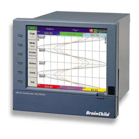
Brainchild VR06 User manual

User Manual
Paperless Recorder VR06
UMVR061D
Brainchild Electronic Co., Ltd.
4th Edition, 10/2013

2
Contents
Page
Safety ---------------------------------------------------------------------------------
4
Safety Symbols
----
-
---------------------------------------------------------------------
4
Safety Notes and Precautions
----------------------------------------------------------
4
Static Electricity
-------------------------------
----------------------------------------
5
1. General Description
--------------------------------------------------------------------
6
1.1 Unique Features of Recorder -------------------------------------------------------
6
1. Expandable Input and Output cards ------------------------------------------------
6
1.3 Communication ---------------------------------------------------------------------
---
6
1.4 Storage Media CF card -----------------------------------------------------------------
7
1.5 Data Security --------------------------------------------------------------------------
7
1.6 Infrared Detector ---------------------------------------------------------------------
7
1.7 Ordering Codes and Accessories --------------------------------------------------
8
1.8 Specifications ------------------------------------------------------------------------
-
11
2. Installation and wiring
-------------------------------------------------------------------
14
.1 Unpacking -------------------------
----------------------------------------------------------
14
.
Installation
----------------
----------
-------------------------------------
---
----------------------
1
4
.3
Setup Input
, Ou
tput
& 4VDC power supply cards
-------------
---
----------------------
1
.4
Wiring of the cards
----
--------
---------------------------------
---
---------------------
3
.5
RS
-
3 , RS
-
4 , RS
-
485 wiring
----------------------------------
----
--------------------
6
.
6
Install
a
tion of Compact Flash
CF Card
-------------------------------
----
--------------------
8
. Basic Operation
----------------------------------------------------------------------------
9
3.1 Page --------------------------------------------------
------------------------------------
9
3. Mode ---------------------------------
----------------------------------------------------
30
3.3 History --------------------------------------------------
------------------------------------
31
3.4 Event ----------------------------------------------
------------------------------------
3
3.5 Status ---------------------------------------------
-------------------------------------
33
3.6 Exit --------------------------------------------------
--------------------------------------
33
3.7 Dump ---------------------------------------------
----------------------------------------
34
3.8 Clear -----------------------------------------
---------------------------------------------
34
3.9 Operate --------------------------------------
---------------------------------------------
34
3.10
Shutdown -----------------------------------
---------------------------------------------
34
3.11
Logout ------------------------------------------------------------------------------------
34
3.1
Small Icons ---------------------------------
----------------------------------------------
35
4.
Configuration
---------------------------------------------------------------------
36
4.1 Channel ( Analog input, Digital input, Analog output, Math input )
-------------
37
4. Display
------------------------------------------------------------------------------
43
4.3 Tools ( Timer, Counter & Totalizer ) -------------------------------
-------------------------
45
4.4 Instrument ---------------------
----------------------------------------------------------
50
4.5 Clock -----------------------------------------
-----------------------------------------------------
53
4.6 Security & FDA 1 CFR part 11 compliance
---------------------------------------
54
4.7 Demo -------------------------------
-------------------------------------------------
55

3
4.8
System Info
-----------------------------------------------------------------
-------------
55
4.
9
A
C
onfiguration
Example
----------------------
------
------------------------------------------
56
5. PC software and Communication configuration
----------------------------
57
5.1
Observer I & Observer II PC software guide
-
---------------------
---------------
57
5.
Ethernet
C
onfiguration
-------------------
-------
----------------------------------
61
5.3 RS 3 , RS485, RS4 Configuration ---------------------
----------------------------------
65
5.4 CF card Configuration
---------------------------------------------------------------
70
5.5 Configuration in Real-Time Viewer
-----------------------------------------------------
73
5.6 DDE dynamic data exchange
----------------------------------------------------
77
6. Application examples
----------------------------------------------------------------------------
83
7. Trouble shooting
--------------------------------------------------------------------------
86
8. FAQs frequently asked questions
--------------------------------------------------
89

4
Safety
This recorder is compliant with the requirements of EN61010-1, UL 61010C-1 & CSA C . No. 4-93.
The protection provided by the recorder may be impaired if it is used in a manner inconsistent with its
intended purpose, or in an environment that exceeds the specifications of the recorder. Brainchild
Electronic Co., Ltd. is not liable for customer’s failure to comply with these requirements.
Safety Symbols
The following symbols may be seen on the user manual or recorder labeling.
Caution
Protective Earth
DC Supply
Safety Notes and Precautions
1. The protective earth terminal should be connected first before any other connection is made. To avoid
making the recorder dangerous under fault conditions, any interruption of the protective Earth conductor
inside or outside the recorder is prohibited. Even in the case of a portable unit, the protective earth
terminal must remain connected if the recorder is connected to any hazardous voltage.
. Keep signal and supply voltage wiring separated from one another. If this is impractical, use shielded
cables for signal wiring. Double insulation should be used for signal wiring when the recorder is being
used with hazardous voltage.
3. Do not use the recorder where there is high vibration, or high magnetic field, this could cause damage or
error of measurement.
4. All maintenance or repairs should be carried out with power disconnected, to avoid personal injury, or
damage to the unit.
5. In areas with conductive pollution, adequate ventilation, filtering and sealing need to be installed.

5
6. When cleaning the recorder, handle carefully and use soft dry cloth. Avoid the use of abrasives or any
sharp and hard objects, which would damage the display.
7. Do not operate the recorder if any part has been removed or disassembled. Consult your nearest dealer
at once.
Static Electricity
Appropriate precautions must be taken when handling the recorder. The circuit board, components are
susceptible to damage caused by electrostatic discharge. Take static electricity precautions whilst handling
and inserting Compact Flash Card into the recorder.
To replace the power-line fuse
The power-line fuse is located within the fuse-holder on the power board. For 90- 50 VAC line voltages,
the user must use a .5A/ 50VAC time-lag fuse, and for both 11-18 VDC and 18-36 VDC line voltages, a
5.0A/ 50VAC time-lag fuse must be used.

6
1. General Description
1.1 Unique features of recorder
The VR06 is a well-designed paperless recorder with many outstanding features including:
• 6.4〞TFT Color LCD with VGA Display in 640x480 pixels.
• 6 isolated Analog Inputs in maximum
• Plug & play I/O cards for easy expansion
• Simple and friendly operation
• Infrared detector to prolong lifetime of LCD
• Solid storage media CF card in high capacity
• 174 mm short depth
• Ethernet as standard and optional RS- 3 /4 /485 communication
• High accuracy 18-bit A-D Analog Input
• 15-bit D-A Analog Output.
• 00 milli second sample rate.
• Bench top with convenient portable handle, easy converted into panel mount
1.2 Expandable Input and Output Cards
The recorder is equipped with six-rear expansion slots, which work flexibly with the following plug & play
I/O cards.
Analog Input cards (part number AI181, AI18 , AI183 ) : These three cards are used for 1, , & 3-
channel analog input. Each input is isolated from each other to avoid noise and to ensure stable
measurement. Analog input is configured by DIP switches and jumpers on the card before plugging into
rear expansion slot. Refer 2.3 etting Input and Output Cards.
Digital utput card ( DO181 ): Each card includes 6 alarm relays. Contacts are rated 5 Amp/ 40 VAC
Digital Input card ( DI181 ): Each card includes 6 channels. Logic Low: -5V minimum, 0.8V maximum,
Logic High: - V minimum, 5V maximum
Analog utput cards ( AO183I, AO183V ): Each card includes 3 channels. AO183I is used for 4- 0mA,
0- 0mA current output, and AO183V is used for 0-5V, 1-5V, 0-10V voltage output.
1. Communication
The standard communication interface is Ethernet with protocol IEEE 80 .3 - 10 Base T. Other options are
RS- 3 / RS-4 / RS-485.

7
1.4 Storage Media CF Card
The Solid Compact Flash Memory Card (CF card) GB capacity is a free standard storage media used for
this instrument. Its compact size, anti-dust and anti-vibration features increase its reliability. To read
measured data on CF Card, add a CF reader on USB port of PC. If the recorder is used with 6-channel
inputs, an easy chart to show the maximum days CF can store the data.
CF card GB
Log speed
1 second 1975 days
10 seconds 19750 days
1 0 seconds 37030 days
Each record of data uses bytes of CF card memory.. If the Log Speed ( the recording speed of measured
data ) is set to the fastest speed at 1 second per data, then for a single channel, GB CF card will last
approximately 11850 days [= 048MB / ( bytes x 4 hours x 60 minutes x 60 seconds ).
The following formula is to calculate how many days the CF card could do saving before it is full.
The
?
days = The capacity of CF Card / ( 2 bytes / the Log peed x the working hours per day x 3600
seconds )
To avoid loosing recorded data while storing on PC, it is necessary to insert CF card back again into the
recorder soon after loading recorded data onto PC.
1.5 Data Security
The recorded data is stored in the manufacturer’s special binary format. It is not possible to manipulate
or modify the recorded data. This feature fully guarantees the security of the data.
1.6 Infrared Detector ( IR Detector )
The use of Passive Infrared technology on the recorder is an innovative idea to prolong the lifetime of the
LCD display. The detector senses the movement of body heat from a distance of approximately meters.
This feature works together with the Screensaver. For example, if the IR Sensor is turned on and
Screensaver set to 10 Min, then the display will turn off 10 minutes after the user walks away from the
recorder. The Passive Infra Red detects when the user returns to the recorder and the display turns on
straight away, no need to press any key on the recorder. If the user does not prefer using this function, it
can be disabled.
1.7 Ordering codes and accessories

8
Ordering codes
VR06
– □□□□ – □□□ – □□□
1 2 3 4 – 5 6 7 – 8 9 10
1 Power
4: 90- 50 VAC, 47-63 Hz
5: 0- 8 VAC, 47-63 Hz
6: 11-18 VDC
7: 18-36 VDC
8. 36-7 VDC
2 Analog Input Card
0: none
1: 1 channel withAI181 G: 3 channels with AI183V
: channels with AI18 H: 6 channels with AI183V
3: 3 channels with AI183
4: 4 channels with AI181 & AI183
5: 5 channels with AI18 & AI183
6: 6 channels with AI183
*See AI181/ /3(V) in Accessories below.
3 Digital Input Card
0: none
1: 6 channels
4 Digital Output Card
0: none
1: 6 relays : 1 relays
5 Communication
0: standard Ethernet interface
1: RS- 3 /4 /485 ( three in one ) + Ethernet interface
6 PC software
1: Free basic software Observer I for non-communication application
: Extensive software Observer II for communication of RS- 3 /4 /485 or Ethernet
7 Firmware
1: with Mathematics, Counter & Totalizer & FDA 1 CFR part 11 compliance

9
8 Storage Media
6: GB CF card
9 Case/Mounting
4: standard panel mounting, black case
5: Bench top / portable style with handle, USA power cable, black case
6: Bench top with handle, European power cable, black case
10 Special Option:
0: none
1: 4VDC auxiliary power supply ( for transmitter, 6 channels )
: 3-channel current output
3: 6-channel current output
D: 3-channel voltage output
E: 6-channel voltage output
5. panel mounting with rear power plug and USA power cable
6. panel mounting with front power switch
7. 7=1+5
8. 8=1+6
9. 9=1+5+6
A. A=6+5
B. B=6+G
G: panel mounting with rear power plug and Europe power cable
H: H=1+G
I: I=1+G+6
X: other options

10
Accessories:
Part no. Descriptions
AI181, AI18 , AI183 1, , 3-channel analog input card (TC, RTD, + mA, + V, + mV)
AI183V 3-channel voltage input card (± mA, ± V, ± mV only)
DI181 6-channel digital input card
DO181 6-channel relay output card (AC/DC)
AP181 4 VDC auxiliary power supply card for 6 transmitters
CM181 RS- 3 /4 /485 + Ethernet communication module
CM18 Standard Ethernet communication module
PM181 90- 50 VAC, 47-63 Hz power supply
PM18 11-18 VDC power supply module
PM183 18-36 VDC power supply module
PM184A 90- 50 VAC, 47-63 Hz power supply with power plug and USA power cable
PM184E 90- 50 VAC, 47-63 Hz power supply with power plug and European power cable
PM185 36-7 VDC 47-63 Hz power supply
PM186 0- 8 VAC power supply,
MK181 panel mount assembly kit
MK183B bench top / portable handle assembly kit (black color)
CF 04 GB compact flash card
AS181 Basic PC software bserver I
AS18 Extensive PC software bserver II
AO183I 3-channel current output card
AO183V 3-channel voltage output card
BT18 Boot ROM with Math, Counter & Totalizer & FDA 1 CFR part 11
SC181 The Slot cover of an empty slot
SNA10A RS-485 to RS- 3 converter
UMVR061 User Manual
Notes:
The rear Slots of the recorder will only accept up to 6 optional cards of input, output or 4 VDC
power supply in any combination. For example, 6-channel analog input needs pieces of 3-channel
analog input card AI183. Now it is left 4 empty Slots for other cards.
The basic PC software bserver I is supplied free together with recorder. There is an additional
charge for the extensive PC software bserver II supplied with communication of RS- 3 /4 /485
or Ethernet.
◆ The Ordering Code of standard model without any option is VR06-4X00-011-640. The standard color
of housing is made in black.

11
1.8 Specifications
Power
90- 50VAC, 47-63Hz, 60VA, 30W maximum
11-18VDC or 18-36 VDC, 60VA, 30W maximum
Display
6.4〞TFT LCD, 640X480 pixel resolution, 56 colors
Memory
16MB storage memory on board
Storage media: GB CF ( Compact Flash ) cards
Analog Input Cards (AI181, AI182, AI183)
Channels: AI181 ~ 1 channel, AI18 ~ channels, AI183 ~ 3 channels
Resolution: 18 bits
Sampling Rate: 5 times/ second
Maximum Rating: - VDC minimum, 1 VDC maximum (1 minute for mA input)
Temperature Effect: ±1.5 µV/ ˚C for all inputs except mA
±3.0 µV/ ˚C for mA input
Sensor Lead Resistance Effect:
T/C: 0. µV/ohm 3-wire RTD: .6 ˚C /ohm of resistance difference of two leads
-wire RTD: .6 ˚C /ohm of resistance sum of two leads
Burn-out Current: 00nA
Common Mode Rejection Ratio (CMRR): 1 0dB
Normal Mode Rejection Ratio (NMRR): 55dB
Isolation Breakdown Voltage between channels: 430VAC min.
Sensor Break Detection: Sensor opened for TC, RTD and mV inputs, below 1 mA for 4- 0mA input,
below 0. 5V for 1-5V inputs, unavailable for other inputs
Sensor Break Responding Time: Within 10 seconds for TC, RTD and mV inputs, 0.1 second for 4- 0 mA
and 1-5V inputs
Characteristics:
Type Range Accuracy Input
at 5 ˚C Impedance
J -1 0 ~ 1000 ˚C ±1 ˚C . MΩ
(-184 ~ 183 ˚F)
K - 00 ~ 1370 ˚C ±1 ˚C ˚ . MΩ
(-3 8 ~ 498 ˚F)
T - 50 ~ 400˚˚C ±1 ˚C . MΩ
(-418 ~ 75 ˚F)
E -100 ~ 900 ˚C ±1 ˚C . MΩ
(-148 ~ 165 ˚F)
B 0 ~ 18 0 ˚C ± ˚C . MΩ
(3 ~ 3308 ˚F) ( 00 ~ 18 0 ˚C)
R 0 ~ 1768 ˚C ± ˚C . MΩ
(3 ~ 3 14 ˚F)
S 0 ~ 1768 ˚C ± ˚C . MΩ
(3 ~ 3 14 ˚F)
N - 50 ~ 1300 ˚C ±1 ˚C . MΩ
(-418 ~ 37 ˚F)
L - 00 ~ 900 ˚C ±1 ˚C . MΩ

12
(-3 8 ~ 165 ˚F)
PT100 - 10 ~ 700 ˚C ±0.4 ˚C 1.3KΩ
(DIN) (-346 ~ 1 9 ˚F)
PT100 - 00 ~ 600 ˚C ±0.4 ˚C 1.3KΩ
(JIS) (-3 8 ~ 111 ˚F)
mV -8 ~ 70mV ±0.05% . MΩ
mA -3 ~ 7mA ±0.05% 70.5Ω
0~1V -0.1 ~ 1.15V ±0.05% 33 KΩ
0~5V -1.3 ~ 11.5V ±0.05% 33 KΩ
1~5V -1.3 ~ 11.5V ±0.05% 33 KΩ
0~10V -1.3 ~ 11.5V ±0.05% 33 KΩ
Analog Input Cards (AI183V)
Characteristics:
Type Range Accuracy Input
at 5 ˚C Impedance
-60~60mV -6 ~6 mV ±0.1% . MΩ
- ~ V - . ~ . V ±0.3% 33 KΩ
- 0~ 0 V - ~ V ±0.1% 33 KΩ
- 0~ 0 mA - ~ mA ±0.1% 70.5Ω
Digital Input Card (DI181)
Channels: 6 per card
Logic Low: -5V minimum, 0.8V maximum
Logic High: V minimum, 5V maximum
External pull-down Resistance: 1KΩ maximum
External pull-up Resistance: 1.5MΩ minimum
Digital utput Card (D 181)
Channels: 6 per card
Contact Form: N.O. (form A)
Relay Rating: 5A/ 40 VAC, life cycles 00,000 for resistive load
Analog utput Card (A 183I, A 183V)
Channels: 3 per card
Output signal: AO183I: 4- 0mA, 0- 0mA, AO183V: 0-5V, 1-5V, 0-10V
Resolution: 15 bits
Accuracy: ±0.05% of Span ±0.00 5% /˚C
Load Resistance: 0-500 ohms (current), 10K ohms minimum (voltage)
Output Regulation: 0.01% for full load change
Output Setting Time: 0.1 second (stable to 99.9%)
Isolation Breakdown Voltage: 1000VAC min.
Integral Linearity Error: ±0.005% of Span
Temperature Effect: ±0.00 5% of Span /˚C
24VDC Auxiliary Power Supply Card (AP181)
Channels: to be used for 6 transmitters
Output Rating: 4 ± 1 VDC, 180mA in maximum, 30mA / each channel

13
C MM Module (CM181)
Interface: RS- 3 (1 unit), RS-485 or RS-4 (up to 47 units)
Protocol: Modbus Protocol RTU mode
Address: 1- 47
Baud Rate: 0.3~38.4 Kbits/sec.
Measured data Bits: 7 or 8 bits
Parity Bit: None, Even or Odd
Stop Bit: 1 or bits
Standard Ethernet Communication
Protocol: Modbus TCP/IP, 10 Base T
Ports: AUI (Attachment Unit Interface) and RJ-45, Auto- detect capability
Infrared Detector
Distance: Detect moving human body in distance around meters
Time delayed: 10, 0, 30, 40, 50 or 60 minutes to be defined
Real time clock accuracy vs. temperature inside of housing
Temperature inside housing typical error per month
10 ~ 40 ˚C 18 seconds
0 ˚C or 50 ˚C 5 seconds
-10˚C or 60 ˚C 107 seconds
Environmental & Physical
Operating Temperature: 5 ~ 50 ˚C
Storage Temperature: - 5 ~ 60 ˚C
Humidity: 0 to 80% RH (non-condensing), maximum relative humidity 80% for temperature up to 31˚C
decreasing linearly to 50% relative humidity at 40˚C
Altitude: 000 M maximum
Insulation Resistance: 0 M ohms min. (at 500 VDC)
Dielectric Strength: 1350 VAC, 50/60 Hz for 1 minute
Vibration Resistance: 10-55 Hz, 10m/ s² for hours
Shock Resistance: 30m/ s² (3g) for operation, 100g for transportation
Operation Position: no inclined restriction
Dimensions: Panel Mount style: 166(W) x 144(H) x 174mm(D)
Bench Top style: 166 (W) x 19 (H) x 194mm (D)
Standard Panel Cutout: DIN size in 138 x 138mm
Approval Standards
Safety: UL61010C-1, CSA C . No. 4-93
CE: EN61010-1 (IEC1010-1) over voltage category II, Pollution degree
Protective Class: IP 30 front panel for indoor use,
IP 0 housing and terminals
EMC:
Emission: EN613 6 (EN550 class A, EN61000-3- , EN61000-3-3)
Immunity: EN613 6 (EN61000-4- , EN61000-4-3, EN61000-4-4,
EN61000-4-5, EN61000-4-6, EN61000-4-8, EN61000-4-11)

14
2. Installation and wiring
2.1 Unpacking
If any damage is found while unpacking, the user should contact the local representative at once. It is
suggested that the special packaging is retained for possible future requirement.
2.2 Installation
Remove stains from this equipment using a soft, dry cloth. Don’t use harsh chemicals, volatile
solvent such as thinner or strong detergents to clean the equipment in order to avoid deformation.
The recorder is designed for indoor use and not in any hazardous area. It should be kept away from shock,
vibration, and electromagnetic fields such as variable frequency drives, motors and transformers.
It is intended to operate under the following environment:
Pollution Degree Level II IEC1010-1( EN61010-1 )
Temperature 5 ~ 50 ˚C
Humidity 0 ~ 80 % RH ( non-condensing )
Power 90 ~ 50 VAC, 50/60 Hz
11-18 VDC or 18 - 36 VDC
Panel mounting style
The front side
Figure 2 - 1

15
The right side
Figure 2 - 2
Panel Cutout ( standard DIN size 138 mm x 138 mm )
Figure 2 - 3
Note:
Do not over tighten mounting clamp screws that could result in distortion of the case.
There is no mounting angle restriction.

16
Bench top / Portable style
If the recorder is used for Bench Top or portable purpose, then the assembly Kit MK183B (two ears, one
handle, two feet included) is required. Assemble as follows,
Firstly, put the right ear FV-R on the right hand side of metal case, and slide it into the case by pushing in
direction as shown in Figures 2-4 through Figure 2-8. Ensure that the ear is firmly plugged into case. Do
the same with the left ear FV-L.
Figure 2 - 4
Figure 2 - 5

17
Figure 2 - 6
Figure 2 - 7
Figure 2 - 8

18
Holding the handle so that the instruction side can be seen, pull the handle outward by both hands and put it
in vertical position on the top of case. Then, slide the handle into both ears as Figure 2-9. Rotate the
handle downward as Figure 2-10 & 2-11. Lastly, slide both feet beneath the case and straighten up the
stoppers as Figure 2-12 〜 Figure 2-14. The bench top recorder is now mechanically ready.
Figure 2 - 9

19
Figure 2 - 10
Figure 2 - 11

20
Figure 2 – 12
Figure 2 – 13
Figure 2 – 14
Note:
To change the bench top into panel mount. Disassemble kit MK183B (one handle, two feet, and two
ears) in reverse of above, then fit the mounting clamps.
Table of contents
Other Brainchild Voice Recorder manuals
