Avisoft UltraSoundGate 416H User manual

Components of the UltraSoundGate 416H
6
9
Introduction
Thank you for purchasing Avisoft UltraSoundGate 416H. This us-
powered USB device supports 4 channel high-speed data
acquisition at sampling rates of up to 750 kHz.
The accompanying recording software Avisoft-RECORDER USGH
provides either continuous or triggered direct-to-disk recording with
real-time spectrogram displays.
Getting started
The supplied RECORDER USGH software can e launched from
Start / All Programs / Avisoft ioacoustics / RECORDER USGH.
On the first program start, the configuration dialog ox will e
launched automatically (otherwise it is availa le from Options /
Configuration). Select the desired Sampling rate from the Input
Device Settings section and click at Ok. Then click at the Pause
utton (Monitoring/Pause) and the Start utton (Monitoring/Start).
You will then see the real-time spectrogram displaying the incoming
signals. For details on the operation of the RECORDER software
see the Avisoft-RECORDER manual and the section RECORDER
USGH Software Settings in this guide.
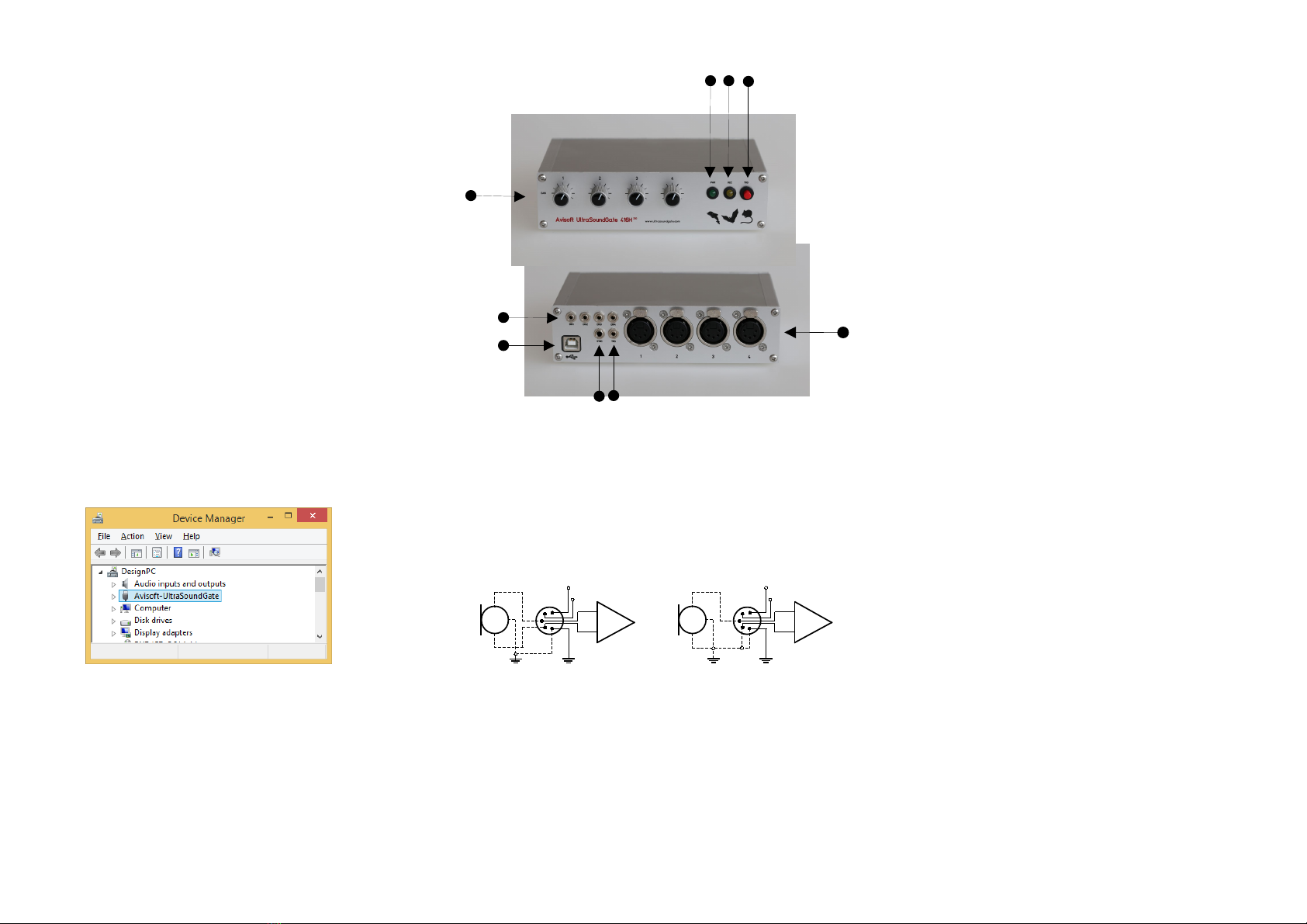
1 XLR input connectors
The 5-pole XLR input connectors represent the analog inputs of the
recording device and provide power supply voltages for external
amplifiers and microphones. The connector scheme is as follows:
2 US 2.0 interface
Use this USB socket to connect the device to the computer.
3 TRIGGER input/output
This 2-pole (mono) 2.5 mm mini-jack connector is electrically
connected to the TRG utton (7) and allows connecting an external
trigger. This input is TTL-compati le (there is additionally an internal
pull-up resistor of 10 kOhm to Vcc). Pulling this input to ground (for
instance y closing a simple switch) will activate the logic USG TRG
button. See the last page on how to congigure the TRIGGER socket
as an output
1
2
3-
+
differential source
45
+200V
+5V
1
2
3-
+
single-ended source
45
+200V
+5V
4 DIN
These 2-pole 2.5mm mini-jack connectors allow to connect
external digital signals. These inputs are TTL-compati le (internal
pull-up resistor of 10 kOhm to Vcc). The status of this signal is
stored in the LSB ( it 0) of the 16- it data words that are
transmitted over the USB and can e used as a sample-precise
trigger source in the RECORDER software. It can e extracted
afterwards y the Avisoft-SASLa Pro sound analysis software
(e.g. for creating la els). The digital inputs are not availa le in the
8- it recording mode.
For a relia le electrical connection, a Switchcraft 0.01” Micro Plug
(part num er 850X) is recommended.
5 SYNC input/output
This socket allows to synchronize the sample clock signals of
several UltraSoundGate units. To accomplish this, all devices must
e connected to a single computer and one device must e
configured as the master (see section RECORDER USGH
Settings for details on this).
6 TRG button
This utton can control the .wav file recording process in the
RECORDER software. To ena le this mode of operation, one of
the following Trigger source options must e selected from the
configuration dialog ox:
USG TRG button auto hold : Pressing the utton for more than 2 seconds will
activate an auto hold mechanism (the recording continues after releasing the utton and
will stop once the utton is pressed again). If the utton is pressed for less than two
seconds, it will only record as long as the utton is eing pressed.
USG TRG button : The software will record as long as the utton is pressed.
USG TRG button inversed : The software will record as long as the utton is not
pressed (or as long as the external TRG signal is not active (logic high)).
USG TRG button toggled : The software will start recording once the utton is
pressed and continues until the utton is pressed again.
7 REC indicator
This am er colored LED will flash once the device is connected to
the PC. It will e switched off once the RECORDER USGH
software is running the in the monitoring mode. In this mode, the
REC LED indicates whether the RECORDER software is recording
the incoming data onto disk.
8 POWER indicator
This green LED indicates that the unit is connected to the USB
power supply.
9 GAIN control knobs
The control kno s adjust the analog input recording levels for each
channel.
78
21
3
4
5
1 Ground
2 Positive input
3 Negative input
4 +5V supply voltage (max current 20 mA)
5 +200V polarization voltage
Installation procedure
First install the RECORDER USGH software either from the
supplied software installation media (navigate to the su folder
RECORDER USH and run setup.exe) or from the Avisoft
Bioacoustics we site (www.avisoft.com/downloads.htm or directly
www.avisoft.com/RECORDER USGH.exe). This installation
program will install oth the RECORDER USGH application
(rec_usgh.exe) and the required device drivers (usgh_xx16h.inf,
usgh.sys) for the UltraSoundGate xx16H devices. When the
installation procedure has completed, the UltraSoundGate unit can
e connected to the computer. The device should then e detected
as “Avisoft-UltraSoundGate 416H” and the pre-installed driver
should e finally activated.
Under some circumstances it might happen that the silent
installation of the device driver fails. If that happens, navigate to the
Windows Control Panel > Hardware and Sound > Device Manager
and right-click at the entry Other devices > visoft UltraSoundGate
416H and select the Update Driver Software... option. Then click at
Browse my computer for device driver software, click at Browse and
navigate to the folder C:\Program Files (x86)\ visoft
Bioacoustics\RECORDER USGH\Drivers and finally click at Next.
The completed device driver installation will then look like this:

RECORDER USGH Settings
User's Guide Model 416H
The configuration dialog ox can e launched from the menu
Options/Configuration... or through the utton
There is a list of 24 virtual channels at the top of the
configuration panel. Each of these virtual channels can e
assigned to a physical channel of the UltraSoundGate unit y
selecting the desired Device and Channel num er for each list
entry. The utton la eled “Ena le all” will assign and activate
all availa le channels automatically.
The sample rate can e selected from the Input Device
Settings section and will always apply to all channels of the
selected UltraSoundGate device. Availa le sample rates are
750, 500, 375, 300, 250, 214, 187.5, 166.6, 150, 125, 100, 75,
62.5 and 50 kHz.
The Buffer setting determines the USB transfer uffer size on
the PC. Shorter durations will provide low real-time
spectrogram display latencies ut might lead to erroneous
USB transfers under certain conditions.
Enable master/slave mode for synchronizing several devices If
you use more than one UltraSoundGate XX16H device, it is possi le to
synchronize their A/D converter sampling clock signals y connecting them
through the SYNC sockets and activating this option (a 3 pole ca le fitted with
3.5mm phone plugs is required) . In such a set-up, one device acts as the clock
master and the other devices listen to the clock signal as slaves.
Activate slave mode for this device In the master/slave mode, one
devices acts as the master and the others as slaves. So, this option must e
disa led on the unit that should act as the master and must ena led on all
other slave units (all USG XX16H devices can act either as slave or master).
Enable low power mode The A/D converter chips can optionally e
operated in a power-saving mode that would increase the attery life in mo ile
laptop- ased systems. The low-power mode slightly degrades the dynamic
range performance. This option should also e activated if the USG 1216H is
us-powered from a single USB port only. Otherwise, the supply voltage might
drop elow a critical value, which can prevent the proper operation of the A/D
converters.
Enable band-pass mode At a few sample rates (50, 62.5, 75, 150, 187.5,
250 and 375 kHz), the A/D converters can e configured for a special and-
pass mode in which the analog input andwidth ranges from fs/2 to fs instead
of the normal mode from 0 to fs/2. This option can e advantageous for
monitoring applications that require minimal .WAV files sizes. Note that the
frequency scale of the resulting .WAV files will e reversed.
Turn on the polarization voltage This option activates the internal 200V
polarization voltage generator of the UltraSoundGate XX16H devices and must
e activated when using the CM16/CMPA microphones.
Ignore GetOverlappedResult error By default, the GetOverlapped
Result error message will stop the monitoring/recording process. If this option is
activated, the monitoring procedure will e immediately restarted, which is
desired in long-term monitoring applications.
TRG out mode This option allows to change the I/O direction of the TRG
socket. If activated, the TRG socket will e configured as a digital output that
carries the state of the internal trigger or file saving state as selected from the
Control Output settings dialog ox (Ctrl Out... utton). In this case, the USG
TRG button trigger source options will not work. The TRG out mode option is
only availa le on units that have the firmware version 1.1 or higher.
Enable safe multichannel data transfer mode Under some
circumstances it might happen that the PC is una le to relia ly transfer
multichannel data streams through the USB interface without gaps. This can
ecome a serious pro lem when the sample rates and the num er of channels
are high and if the latency of the Windows operating system is poor (due to
insufficient processing power or mis ehaving device drivers). So, if you
encounter any pro lems while recording more than one channel (sporadically
mixed-up channels), this option should e activated. The RECORDER software
will then immediately correct such false channel associations. Due to certain
system constraints, this option is not availa le at the sample rate of 750 kHz
The Settings... utton in the
Input Device Settings
section launches the
dvanced USGH Device
Settings dialog ox that
provides several additional
device options:

Avisoft Bioacoustics e.K.
Schönfließer Str. 83
16548 Glienicke/Nord ahn
Germany
Phone: +49 (0)33056 426086
Fax: +49 (0)33056 426087
www.avisoft.com
www.ultrasoundgate.com
Sound-activated recording can e arranged y selecting the
Trigger source option level of this channel. For remote-
controlled triggering via the trigger utton on the device or via the
external TRG input, one of the trigger options USG TRG button
can e used. For triggering y a TTL signal attached to DIN,
select UltraSoundGate DI.
The Pre-trigger duration should e kept as short as possi le. Long
pre-trigger settings can lead to data transmission errors if the
sample rate and the num er of channels is high.
In order to simplify the operation of the Avisoft-RECORDER
software in the field, a link to RECORDER USGH may e added
to the Windows Startup folder (Start-> ll Programs->Startup).
Additionally, the Avisoft-RECORDER option
Monitoring/Autostart should e activated. This arrangement will
start the monitoring process automatically after ooting the laptop
computer (the UltraSoundGate device must e attached to the
USB port prior to ooting Windows).
When the system is operated on a attery-operated laptop or
ta let PC, it is recommended to disa le any power saving options
that might otherwise lead to occasional loss of data (short gaps in
the recordings) or temporarily interchanged channels.
Please refer to the users guide or the online help system for
further details on the Avisoft-RECORDER software.

Num er of channels 4 (4 separate A/D converters)
ADC type Delta-Sigma architecture with
integrated adaptive anti-aliasing filter
Resolution 16 it or 8 it
Maximum aggregate
sample rate 4 x 750 kHz / 16 it
Sample rates [kHz] 750, 500, 375, 300, 250, 214, 187.5,
166.6, 150, 125, 100, 75, 62.5, 50
Frequency response (-3dB) 20 Hz - 370 kHz
Input sensitivity (max trim) -43.2dBV = -41 dBu = 6.9 mVrms
Input sensitivity (min trim) -3.2dBV = -1 dBu = 0.69 Vrms
Gain adjustment potentiometer 40 dB continuous range
Input impedance 50 kOhm
Analog input connectors female XLR-5 sockets
Other inputs external trigger (TTL-compati le),
4 digital inputs (TTL-compati le),
SYNC in/out
Computer interface USB 2.0,
isochronous high-speed mode
Supply current
(drawn from the USB) 450mA
Physical dimensions (W/H/D) 163 x 42 x 125 mm
Weight 620 g
Specifications
In the interest of product improvement, the specifications and/or
appearance of this unit are su ject to change without notice.
Windows PC with at least one USB 2.0 port, Intel Core i5 processor
or higher, running Windows Vista / 7 / 8 / 10
Computer requirements

Specifications
In the interest of product improvement, the specifications and/or
appearance of this unit are su ject to change without notice.
Windows PC with at least one USB 2.0 port, Intel Core i5 processor
or higher, running Windows Vista / 7 / 8 / 10
Num er of channels 4 (4 separate A/D converters)
ADC type Delta-Sigma architecture with
integrated adaptive anti-aliasing filter
Resolution 16 it or 8 it
Maximum aggregate
sample rate 4 x 750 kHz / 16 it
Sample rates [kHz] 750, 500, 375, 300, 250, 214, 187.5,
166.6, 150, 125, 100, 75, 62.5, 50
Frequency response (-3dB) 20 Hz - 370 kHz
Input sensitivity (max trim) -28.4 dBV = -26.2 dBu = 38.0 mVrms
Input sensitivity (min trim) 1.6 dBV = 3.8 dBu = 1.2 Vrms
Gain adjustment potentiometer 30 dB range with 3 dB increments
Input impedance 50 kOhm
Analog input connectors female XLR-5 sockets
Other inputs external trigger (TTL-compati le),
4 digital inputs (TTL-compati le),
SYNC in/out
Computer interface USB 2.0,
isochronous high-speed mode
Supply current
(drawn from the USB) 450mA
Physical dimensions (W/H/D) 163 x 42 x 125 mm
Weight 600 g
Computer requirements
Table of contents