Braintree Scientific Learn & Repeat BS-900 User manual
Publication #1200-01 Revision 0 10/18/2012
Model: BS-900
Basic User Manual
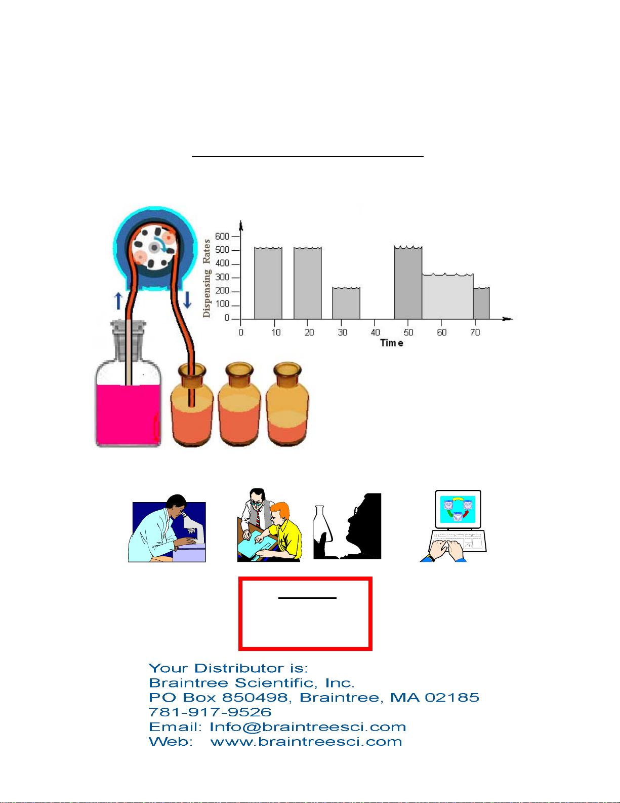
Programmable Peristaltic Pump
“Learn & Repeat”™
“WHAT’S YOUR APPLICATION?”™
WARNING
NOT FOR CLINICAL
USE ON HUMANS

Braintree Scientific, Inc. www.braintreesci.com Model BS-900
Publication #1200-04: Page ii of 37 Revision 0.1 10/18/12
BS-900 Peristaltic Pump
Quick Start Instructions
Assumes that the pump was not previously
programmed with a multiple Phase Pumping
Program. Otherwise execute pump reset.
Plug in the pump. Use appropriate power
supply.
Press the power switch on the back of the pump
to turn on power.
Press any key to stop the display from blinking.
Setup Pumping Parameters
To Change Numbers:
Press the up arrow keys to increment individual
digits.
To set/clear the decimal point:
Simultaneously press the 2 up-arrow keys under
the 2 digits next to the decimal point position.
Press any non-arrow key, or wait for the display
to blink. The new value is entered and stored in
memory.
Peristaltic Tube ID (Inside Diameter):
Tubing diameter is pre-set to 3/16” ID. See full
instructions to change the default tubing
diameter.
Set the Pumping Rate:
Display the pumping rate by momentarily
pressing the ‘Rate’ key.
To change the pumping rate units:
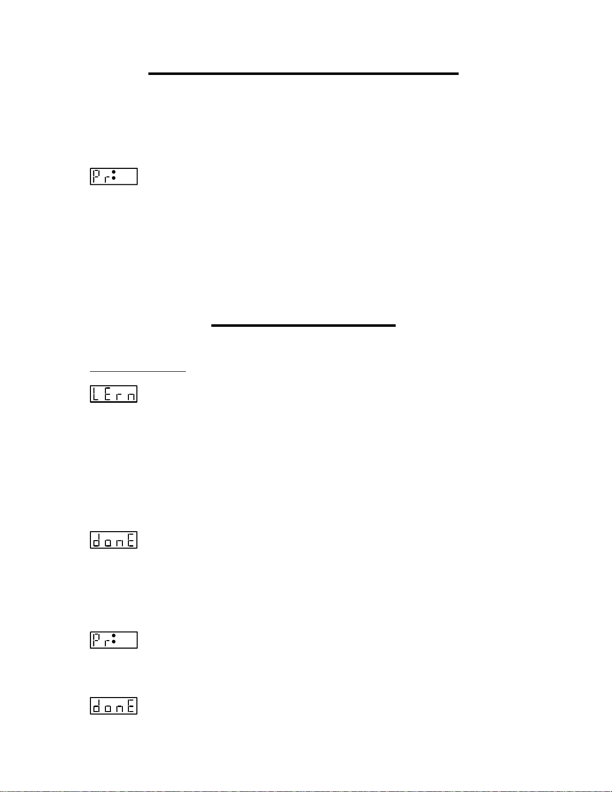
Momentarily press the ‘Rate’ key again. The
display will show:
Press any up arrow key to select the next
available rate units while they blink.
Press any non-arrow key, or wait for the time
out to set the rate units.
Set the pumping rate. If the pumping rate is out
of range, the display will show:
Set the Volume to be Dispensed
or Continuous Pumping
Display the volume by momentarily pressing the
‘Volume’ key. ‘Dispensed’ LED should be off.
When the display shows , the pump
is set for continuous pumping. Pressing any up
arrow key will change the display to 0.
For continuous pumping: Set the volume to 0.
For a Volume to be Dispensed: Set the volume.
To change volume units, momentarily press the
‘Volume’ key again. The ‘Dispensed’ LED
should be lit. Use the up arrow keys to select the
volume units.
Set the Pumping Direction
When the ‘Withdraw’ LED is lit, the pump is set
for withdrawing. When not lit, the pump is set
for dispensing. Use the ‘ ’ key to change
the pumping direction.
Load the Peristaltic Tubing
Prepare new tube with two tie wraps 5 3/8”
apart, both knots facing the same direction.
Remove pump head by turning cassette
counterclockwise, Remove rotor.
Add grease to pump shaft and tubing.
Insert rotor onto Shaft, Placing tube between
Cassette and rotor. Tie Wrap knots facing
Cassette.
Install pump head to base by first, lining up rotor
and driving axle, and second applying forward
pressure and rotating cassette clockwise until it
enters its groove. Continue turning until it stops.
Prime/Purge: Press and hold the
‘Start/Stop’ key for one second. Release to
stop.
Start the Pump: Momentarily press
the ‘Start/Stop’ key to start or stop the
pump.
While Pumping
The pumping rate can be changed.
With continuous pumping, the pumping direction
can be changed.
PUMP RESET:
Press and hold the right-most up arrow key while
turning on power to the pump.
Publication #1200-04 revision V0.1 10/18/12
Selecting Dispense Programs
Multiple dispense settings can be stored and selected as needed. The last selected dispensing program will
be the default dispense program when the pump is powered on. Up to 40 dispense programs can be
stored.
To view or select the current dispense program number or to select a different program, press and hold
either the ‘Rate’ or ‘Volume’ key. The display will show:
nn
Where ‘nn’ indicates the currently selected dispense program. Use the arrow keys to change the dispense
program number. Press ‘LEARN’ to select, or wait for the 5 second time out. The display will blink
when selected.
Press the ‘Start’ key to immediately start the selected dispense.
Press the ‘Rate’ or ‘Volume’ keys to display the settings for the selected dispense. Any changes made to
the pumping rate or dispense volume will be stored in the selected dispense program.
Learn and Repeat
Learn and repeat easily teaches the pump a dispense volume. Then you can immediately repeat this
dispense.
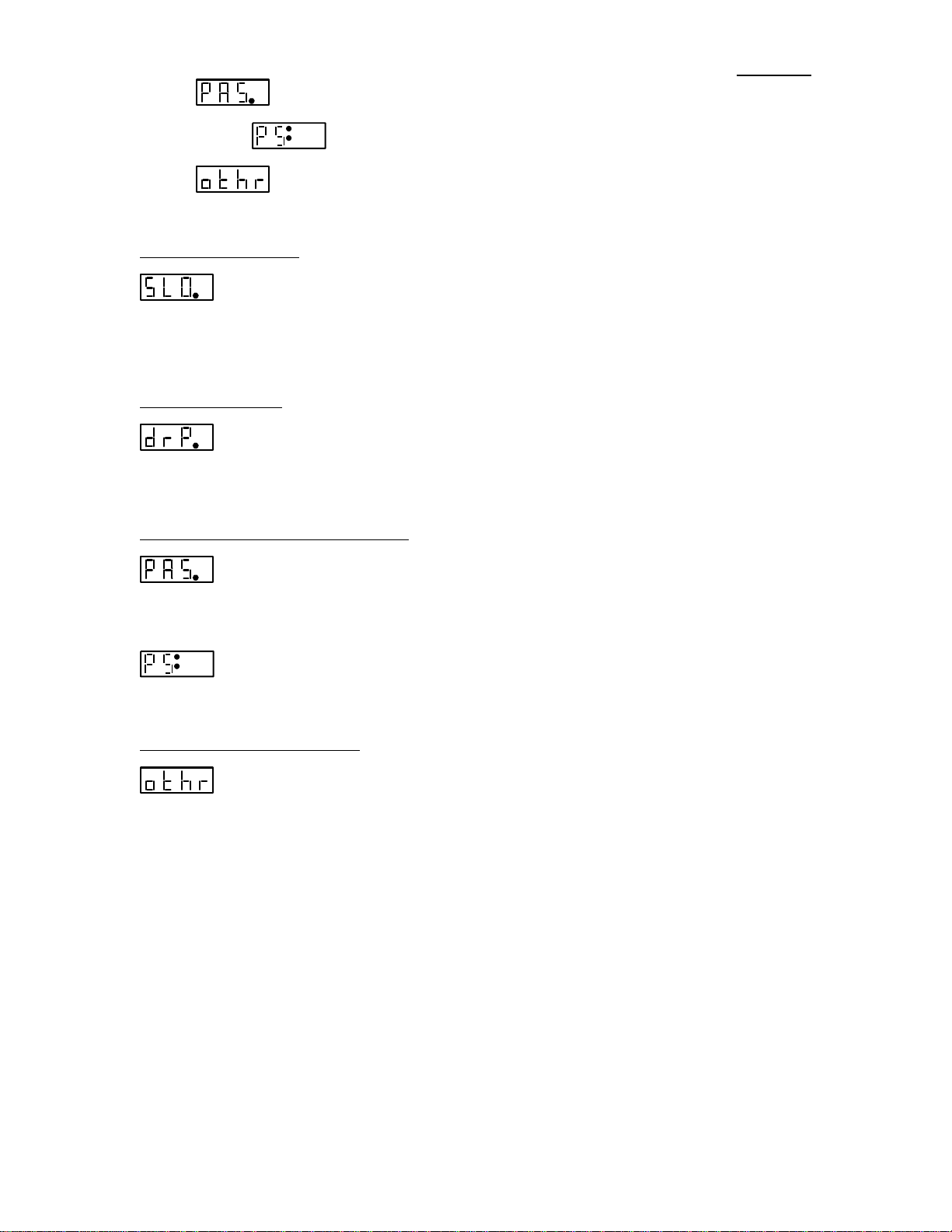
While turning on power, press and hold the ‘LEARN’ key. The display will show:
Press and hold the ‘Start’ key to begin dispensing. As the desired volume is approached, you can release
the key to stop the pump, then periodically press the ‘Start’ key to slowly and accurately approach your
dispense volume.
While pumping, the volume dispensed will be displayed. When the ‘Start’ key is released, the display will
alternate between displaying the volume dispensed and the currently selected dispense setting number.
Press the ‘LEARN’ key, or wait for the time out, to immediately store the dispensed volume in the
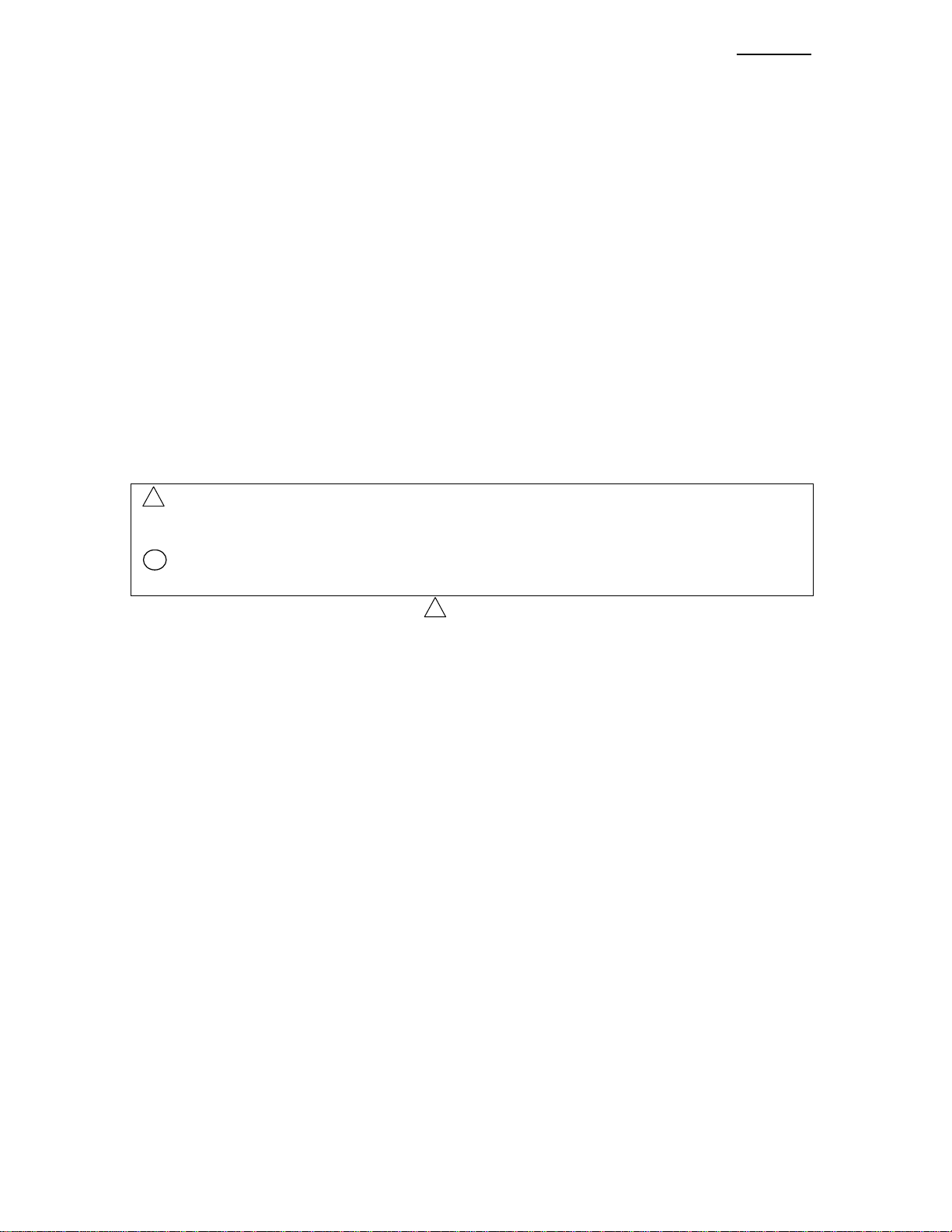
currently selected dispense setting. A double beep will sound and the display will show:
Press any key to return to the currently selected dispense program display.
Press ‘Start’ to immediately begin the newly learned dispensed.
The learned dispense can be stored in a different dispense setting number. After the required dispense
volume is reached, press any of the up arrow keys. The display will show:
nn
Where ‘nn’ is the crrently selected dispense setting number. Use the up arrow keys to select a different
location to store the dispense. Press the ‘LEARN’ button or wait for the time out. A double beep will
sound and the display will show:
Press the ‘Start’ button to immediate begin dispensing the learned dispense.

www.braintreesci.com Braintree Scientific, Inc. Model BS-900
Publication #1200-04 iv 10/18/12
Tubing Calibration
Calibration mode fine tunes the dispense accuracy. Continued use of tubing will cause it to stretch and
deform which creates dispensing errors. Also, differing viscosities and/or pumping speeds can also affect
pumping accuracy.
Calibration uses the currently selected dispense program. Also, you will need a calibrated measuring cup
to verify the actual dispense volume.
To begin calibration: While turning on power, press and hold the ‘LEARN’ key until the display shows:
Press any up arrow key for the next Learn selection: Calibration:
Press the ‘Start’ key to begin the dispense.
When the dispense is complete, the pump will stop, and the dispensed volume will be displayed with the
volume units LED blinking.
Press the ‘LEARN’ key to accept this volume, or use the up arrow keys to enter a measured dispense
volume.
Press ‘LEARN’ after the measured dispense volume has been entered.
The pump uses the entered volume to recalibrate the dispense volumes. Dispense volumes will be
adjusted according to the measured volume entered.
Tubing Inside Diameter Setting
For most applications, the default tubing inside diameter does not need to be changed since the pumping
head is optimized for 3/16” inside diameter (ID) tubing.
If needed, to change the tubing diameter setting, enter Diameter Setting mode:
While turning on power, press and hold the ‘Diameter’ key until the display shows:
Press the ‘DIAMETER’ key again to select. The display will show the current diameter and the ‘mm’
units LED will blink. While the units LED is blinking, use the up arrow keys to enter the new diameter.
For example, to enter 1/8” id tubing, use the up arrow keys to change the display to:
Press the ‘LEARN’ key, or wait for the time out to enter the new setting. The tubing diameter will now
be set to the new setting. The new diameter will be used as the current calibration setting.
Special Modes
Press and hold the ‘Diameter’/’Setup’ key to access the Special Modes setup menu The first mode,
“Slow-Down” will be displayed:
n
Press the’LEARN’ key to move to the next mode, or wait for the time out. The following is the sequence
of diplays:
n Slow Down mode, where ‘n’ is the current setting.
n Anti-Drip mode, where ‘n’ is the current setting.
www.braintreesci.com Braintree Scientific, Inc. Model BS-900
Publication #1200-04 v10/18/12
n Dispense and pause mode, where ‘n’ is the current setting.
nn When pasue mode is enabled, displays the pause setting.
Display secondary setup menu: Press any up arrow key to select.
Slow Down Mode
n Setting: ‘0’ = Disabled, ‘1’ = Enabled.
Slow-Down mode prevents over dispensing when pumping a large volume at a high speed. When
enabled, the pumping speed will ramp down as the volume dispensed approaches the target dispense
volume.
Anti-Drip Mode
n Setting: ‘0’ = Disabled, ‘1’ = Enabled.
When enabled, Anti-Drip mode will withdraw a small volume after the completion of a dispense to
prevent dripping or oozing when the pump stops. The volume withdrawn is added to the next dispense.
Dispense, Pause, Repeat Mode
n Setting: ‘0’ = Disabled, ‘1’ = Enabled.
When enabled, will create a more automated dispensing system, whereby the pump will continuously
repeat the current dispense after a fixed time delay. The time delay will be displayed next:
nn
Where ‘nn’ is the pause time in seconds. Use the arrow keys to change the dispense time.
Advanced Settings Menu
The “Other” menu selection provides access to the additonal settings menu.

www.braintreesci.com Braintree Scientific, Inc. Model BS-900
Publication #1200-04 110/18/12
Table of Contents
1. GENERAL INFORMATION...........................................................................................3
1.1. SAFETY............................................................................................................................3
1.2. DISCLAIMER....................................................................................................................4
1.3. WARRANTY .....................................................................................................................4
1.4. PACKING LIST.................................................................................................................5
2. OVERVIEW ......................................................................................................................5
2.1. GLOSSARY OF TERMINOLOGY AND CONCEPTS............................................................4
3. SETUP................................................................................................................................5
4. LOADING PERISTALTIC TUBING.............................................................................6
4.1 REMOVE TUBING FROM PUMP............................................................................................6
4.2. INSTALL NEW TUBING........................................................................................................7
5. PERISTALTIC TUBING.................................................................................................8
6. USER INTERFACE..........................................................................................................8
6.1. ENTERING VALUES.........................................................................................................8
6.2. LCD DISPLAY .................................................................................................................9
6.3. LEDS...............................................................................................................................9
6.4. ARROW AND DECIMAL POINT KEYS .............................................................................9
6.4.1. DECIMAL POINT KEY..............................................................................................10
6.5. ‘DIAMETER’AND ‘SETUP’KEY....................................................................................10
6.6. ‘RATE’AND ‘LEARN /PROGRAM PHASE #’ KEY........................................................10
6.6.1. PUMPING RATE UNITS ............................................................................................10
6.6.2. PROGRAM ENTRY MODE OR DISPENSE SELECTION................................................11
6.7. ‘VOLUME’AND ‘PROGRAM FUNCTION’KEY .............................................................11
6.7.1. DISABLING “VOLUME TO BE DISPENSED”..............................................................11
6.7.2. CLEARING “VOLUME DISPENSED” .........................................................................11
6.7.3. VOLUME UNITS.......................................................................................................11
6.7.4. PROGRAM ENTRY MODE ........................................................................................11
6.8. PUMPING DIRECTION KEY...........................................................................................12
6.9. ‘START’/’STOP’KEY ....................................................................................................12
6.10. DISPENSE SELECTION...............................................................................................12
6.11. ‘SETUP’KEY..............................................................................................................12
6.12. SPECIAL SETUP KEY.................................................................................................13
6.13. LEARN KEY ...............................................................................................................13
6.14. SPECIAL POWER-UP FUNCTIONS.............................................................................13
6.14.1. FIRMWARE VERSION DISPLAY............................................................................13
6.14.2. RESET THE PUMP.................................................................................................13
6.14.3. LEARN AND CALIBRATE SELECTION...................................................................13
6.14.4. SPECIAL SETUP....................................................................................................13
6.15. ERROR AND ALARM MESSAGES...............................................................................14
6.16. STATUS MESSAGES ...................................................................................................14
7. OPERATION...................................................................................................................15
7.1. PERISTALTIC TUBE INSIDE DIAMETER .......................................................................15
7.1.1. CHANGING VOLUME UNITS....................................................................................15
7.2. STORED DISPENSE SELECTIONS ..................................................................................15
7.3. START/STOP TRIGGERS................................................................................................15

www.braintreesci.com Braintree Scientific, Inc. Model BS-900
Publication #1200-04 210/18/12
7.4. OPERATING THE PUMP.................................................................................................16
7.5. PRIME AND PURGING....................................................................................................16
7.6. CHANGING THE PUMPING RATE AND DIRECTION WHILE PUMPING........................16
7.7. VOLUME DISPENSED.....................................................................................................16
7.8. RESUMING WHEN PAUSED...........................................................................................17
8. LEARN AND REPEAT ..................................................................................................17
9. CALIBRATION ..............................................................................................................18
10. SETUP CONFIGURATION ..........................................................................................18
10.1. SLOW DOWN MODE..................................................................................................19
10.2. ANTI-DRIP MODE......................................................................................................19
10.3. DISPENSE,PAUSE,REPEAT MODE ...........................................................................20
10.4. ADVANCED SETTINGS MENU....................................................................................20
10.5. POWER FAILURE MODE ...........................................................................................20
10.6. AUDIBLE ALARM ENABLE........................................................................................20
10.7. TTL I/O OPERATIONAL TRIGGER CONFIGURATION .............................................20
10.8. TTL I/O DIRECTIONAL CONTROL INPUT CONFIGURATION..................................21
10.9. PUMP MOTOR OPERATING TTL OUTPUT CONFIGURATION .................................21
10.10. KEYPAD LOCKOUT ...................................................................................................21
10.11. KEYPAD BEEP ENABLE.............................................................................................22
10.12. RS-232 PUMP NETWORK CONFIGURATION ............................................................22
10.13. SET TUBING INSIDE DIAMETER SETTING................................................................22
10.14. SET DISPENSE MODE ................................................................................................23
10.15. SET PROGRAM MODE LOCKOUT .............................................................................23
10.16. EXIT SPECIAL SETUP MENU ......................................................................................23
11. PUMPING PROGRAM..................................................................................................23
12. RS-232 COMMUNICATIONS.......................................................................................23
13. LOGIC INTERFACE: TTL INPUT AND OUTPUT .................................................23
13.1. TTL I/O OPERATIONAL CONTROLS........................................................................25
13.2. TTL I/O CONTROL FROM THE PUMPING PROGRAM..............................................26
13.3. TTL I/O CONTROL FROM RS-232 ...........................................................................26
14. APPENDIX ......................................................................................................................26
14.1. RS-232 COMMAND SUMMARY .................................................................................26
14.2. RS-232 PUMP NETWORK CONNECTOR WIRING.....................................................27
14.3. ACCESSORIES ............................................................................................................28
14.3.1. ANA-BOX..........................................................................................................28
14.3.2. RS-232 NETWORK CABLES.................................................................................28
14.3.3. AUTOMATION CABLE:DUAL PUMPS CONTROL CABLE.....................................28
14.3.4. VALVE CONTROLLER..........................................................................................28
14.3.5. FOOT SWITCH......................................................................................................28
14.3.6. LOCKOUT DISABLE KEY .....................................................................................28
14.3.7. FIRMWARE UPGRADE..........................................................................................29
14.4. TROUBLESHOOTING AND MAINTENANCE ...............................................................29
14.5. SPECIFICATIONS........................................................................................................29
14.5.1. MECHANICAL &ELECTRICAL.............................................................................29
14.5.2. OPERATIONAL .....................................................................................................29
14.6. CUSTOM APPLICATIONS...........................................................................................30
14.7. TUBE CHEMICAL CHARACTERISTICS......................................................................30
www.braintreesci.com Braintree Scientific, Inc. Model BS-900
Publication #1200-04 310/18/12
1. General Information
Thank you for purchasing the BS-900 Programmable Peristaltic Pump. With the BS-900 peristaltic pump
you will be able to perform simple fluid dispensing or implement a complex automated dispensing system.
Please familiarize yourself with the BS-900’s operation by reading this user's manual. For future
reference, record the serial number, located on the rear of the pump, and the date of purchase.
Serial Number ____________________, Date of Purchase ___________________________,
This Operating Manual, and the BS-900’s hardware, electronics and firmware are copyrighted.
Copyright 1999-2010, all rights reserved.
1.1. Safety
In the interests of safety, this pump and the tubing selected should only be installed and used by
competent, suitably trained personnel after they have read and understood this manual, and considered any
hazards involved.
Markings & Symbols
The following are the meanings of the markings and symbols used in these Safety Precautions.
!
Warning This symbol indicates information that, if ignored or applied incorrectly, creates
the possibility of death or serious personal injury. i.e. fire, explosion.
!
Caution This symbol indicates information that, if ignored or applied incorrectly,
possibility of minor or moderate personal injury or property damage.
!
Warning
Read the user’s manual
This product is designed for liquid only.
User is responsible to determine the suitability of the pump to its desired function.
Verify that tubing is appropriate for liquid being pumped.
Disconnect power from the pump when replacing tubing or connecting or disconnecting cables.
Never leave any dangerous liquid inside of tubing when replacing tubing and disposing pump. Remaining
liquid may cause serious injury.
Never use in atmosphere with flammable gas.
Never use in any location where there is a possibility of high humidity, high temperature, or extreme dust.
Use only with the supplied power supply connected to a power source as specified on the power supply
label.
Never use a voltage that is different from voltage specified in this manual. Unless Authorized by NEW
ERA PUMP SYSTEMS INC.
Do not operate with any foreign matter (water, dirt, metal or other materials) inside the Pump-head.
Do not push objects of any kind into the chassis openings, except for appropriate cables and connectors.
Never try to take the unit apart or modify it except as described in this manual or authorized by NEW
ERA PUMP SYSTEMS INC.. No user serviceable parts inside.
Do not immerse the pump in liquid. If spilling occurs unplug pump immediately.
Install on a stable surface.
The pump can automatically start when the Pumping Program is operating or when attached to an
external control device.
Prevent liquids from entering openings in the rear of the pump.
If the pump becomes damaged, do not use unless certified safe by a qualified technician. Damage
includes, but is not excluded to, frayed cords and deterioration in performance.

www.braintreesci.com Braintree Scientific, Inc. Model BS-900
Publication #1200-04 410/18/12
!
Caution
Do not transport and store this product where the temperature and the humidity are high or fluctuate
greatly, or the product is subjected to direct sunlight.
Remove tubing from pump when not in use. Tubing will become deformed changing dispensed volume
per rotation.
Tubing wall may become permanently damaged if the roller compresses the same part of the tubing for
a long time.
During installation and use, be careful not to cut yourself on the edge of the Pump parts.
Tubing life depends upon chemical and operating environment.
Tubing Chemical compatibility list mentioned is only a guide. The user is responsible to determine the
tubing compatibility to the chemical to be used.
Keep delivery and suction lines as short as possible, use a minimum number of bends.
Pump operates best at medium speeds. At very slow speeds pump will get hot. At high speeds pump
and tubing life will decrease, pump will lose force/ pressure and may stall.
Run at slow speed and use larger diameter tubing when pumping viscous liquid.
User is responsible to determine the maximum speed the pump can operate.
Discharge static from control cables before connecting by touching the cable to ground.
Before touching the pump, discharge static by touching ground.
1.2. Disclaimer
NEW ERA PUMP SYSTEMS INC. makes no representations or warranties, expressed, statutory or
implied, regarding the fitness or merchantability of this product for any particular purpose. Further, NEW
ERA PUMP SYSTEMS INC. is not liable for any damages, including but not limited to, lost profits, lost
savings, or other incidental or consequential damages arising from ownership or use of this product, or for
any delay in the performance of its obligations under the warranty due to causes beyond its control. NEW
ERA PUMP SYSTEMS INC. reserves the right to make any improvements or modifications to the
product described in this manual at any time, without notice.
Design and specifications are subject to change without notice.
The information contained in this document is believed to be correct but NEW ERA PUMP SYSTEMS
INC. accepts no liability for any errors it contains, and reserves the right to modify this document without
notice.
NEW ERA PUMP SYSTEMS INC. products are not designed, intended, or authorized for use in
applications or as system components intended to support or sustain human life, as a clinical medical
device for humans, or for any application in which the failure of the product could create a situation where
personal injury or death may occur.
All brand and product names used in this manual are the trademarks of their respective owners.
1.3. Warranty
NEW ERA PUMP SYSTEMS INC. warranties this product and accessories for a period of two year, parts
and labor, from the date of purchase. The repaired unit will be covered for the period of the remainder of
the original warranty or 90 days, whichever is greater.
The Peristaltic Pump Head Assembly and peristaltic tubing are considered replaceable items and are not
covered under overall product warranty.
A return authorization number must be obtained from NEW ERA PUMP SYSTEMS INC. before
returning a unit for repair. Warranty covered repairs will not be performed without a return authorization
number. At the option of NEW ERA PUMP SYSTEMS INC., a defective unit will be either repaired or
replaced.
This warranty does not cover damage by any cause including, but not limited to, any malfunction, defect
or failure caused by or resulting from unauthorized service or parts, improper maintenance, operation
contrary to furnished instructions, shipping or transit accidents, modifications or repair by the user, harsh
environments, misuse, neglect, abuse, accident, incorrect line voltage, fire, flood, other natural disasters,
or normal wear and tear. Changes or modifications not approved by NEW ERA PUMP SYSTEMS INC.
could void the warranty.
The foregoing is in lieu of all other expressed warranties and NEW ERA PUMP SYSTEMS INC. does not
assume or authorize any party to assume for it any other obligation or liability.

www.braintreesci.com Braintree Scientific, Inc. Model BS-900
Publication #1200-04 510/18/12
1.4. Packing List
Included with the BS-900 Programmable Peristaltic Pump are the following items:
One of the following external unregulated power supply adapters:
Input: One of: 120V AC 60 Hz, 220V AC 50 Hz, 240V AC 50 HZ,
or other custom specified power supply
Output: 24V DC @ 1A
4 feet of Norprene A-60-G®tubing.
4 tie wraps (2 assembled).
0.5oz sample of Super-Lube®.
This Operating Manual
2. Overview
The BS-900 is a general purpose single peristaltic pump capable of dispensing and withdrawal. It is
controlled from a microcontroller based system which drives a step motor, allowing a wide range of
pumping rates configured to the inside diameter of the peristaltic tube.
Features:
Dispense and withdrawal pumping
Pumping rates from 0.041 ml/min to 904.4
ml/min with a 3/16 ID tubing. Depending
on tube characteristics.
Dispense and withdrawal volumes
separately accumulated.
Programmable dispense volumes.
Non-volatile memory of all operating
parameters and Pumping Program.
Programmable Phases allowing complex
pumping applications and interaction with
external devices.
RS-232 bi-directional control.
Built-in pump network driver. Pump
network supports up to 100 pumps and
other devices.
Two modes of RS-232 control, Basic and
Safe. Safe mode provides communication
error detection, loss of communication
detection, and automatic transmitting of
alarm conditions.
TTL I/O with software filtered control
inputs to eliminate glitches and ringing on
the control inputs.
Configurable TTL operational trigger.
Power Failure Mode: Restarts the Pumping
Program after a power interruption.
Audible Alarm.
Many more features!

www.braintreesci.com Braintree Scientific, Inc. Model BS-900
Publication #1200-04 4
2.1. Glossary of Terminology and Concepts
When a device has as many features as the BS-900, understanding its operation could be a daunting task at
first. By understanding the key concepts and terminology used in this manual, the operation of the BS-
900 will become quite intuitive. Every effort has been made to design the BS-900 with a consistent and
intuitive user interface.
To facilitate and enhance your understanding of the BS-900’s operation, please take the time to familiarize
yourself with the basic concepts below:
Fig 1. Pump Head Assembly
Terminology

www.braintreesci.com Braintree Scientific, Inc. Model BS-900
Publication #1200-04 5
Momentar
y
Press: A quick press, less then 1 second, then release of a key on the keypad.
Dis
p
la
y
Blink: A momentary blanking of the LCD display. This indicates that the new data
entered by the user is valid and has taken affect.
Pum
p
in
g
Pro
g
ram
Operating: When the pump is started with the ‘Start’/’Stop’ key, or any other source, the
pump begins performing the operations in the Pumping Program until the
Pumping Program either stops automatically or the pumped is stopped when
the ‘Start/Stop’ key is pressed, or from any other source. While performing
the operations defined in the Pumping Program, the Pumping Program is
referred to as operating.
While Operating, the motor can be pumping or stopped, according to the
Pumping Program.
Pum
p
in
g
Pro
g
ram
Stopped:
The motor is stopped and the pump is not operating the Pumping Program.
Pum
p
in
g
Pro
g
ram
Paused:
The Pumping Program has been stopped, but can be resumed at the point
where it was stopped.
Pum
p
in
g
Pro
g
ram
Resumed: Continuing a Pumping Program that was Paused before the completion of the
Pumping Program. The Pumping Program continues at the point where the
Pumping Program was stopped.
Executed: The pump has performed a single operational Phase as defined in the
Pumping Program.
Start Tri
gg
er: The Pumping Program may be started, or stopped, from multiple sources.
These are the keypad’s ‘Start’/’Stop’ key, the TTL I/O ‘Operational Trigger’
input, or from a command received through the RS-232 connection.
3. Setup
Place the pump on a stable surface.
Plug the round connector end of the supplied power supply adapter into the power plug located on the
lower right of the pump's rear. See section 13, Logic Interface: TTL Input and Output, for a diagram
of the rear of the pump. Plug the other end of the power supply adapter into an appropriate electrical
outlet. The pump will be powered when the bottom of the power switch, located on the upper right of
the rear of the pump, labeled ‘1’, is pressed. The red indicator on the switch is visible when the
power switch is in the ‘on’ position. After power is applied to the pump, the pump’s display will
flash.
Next the Pumping Program can be entered. Before the Pumping Program can be operated, the pump
needs the measurement of the peristaltic tube inside diameter. The peristaltic tube inside diameter can
be entered using the keypad. Refer to ‘Diameter’ and ‘Setup’ Key.
Finally, the peristaltic tube can be loaded and the pump started.

www.braintreesci.com Braintree Scientific, Inc. Model BS-900
Publication #1200-04 6
4. Loading Peristaltic Tubing
!
Remove tubing from pump when not in use. Tubing will become
deformed changing dispensed volume.
4.1 Remove Tubing from Pump
4.1.1. Remove liquid from tubing.
1) Turn on power to the Pump.
2) Press and hold Start/Stop and purge out fluid in Tubing.
3) Remove tubing from liquid.
4) Turn off power to the pump.
!
Warning: Liquid will siphon through tubing when it is removed from pump.
!
Warning: Dangerous Liquid in the tubing may cause injury.
4.1.2. Uninstall Cassette
Turn Cassette counterclockwise until it stops. Then pull it out.
4.1.3. Remove Tubing
1. Remove one side of peristaltic tubing from Cassette.
2. Pull out Tubing. Hold rotor from falling.
3. Remove the other side of tube from Cassette.
www.braintreesci.com Braintree Scientific, Inc. Model BS-900
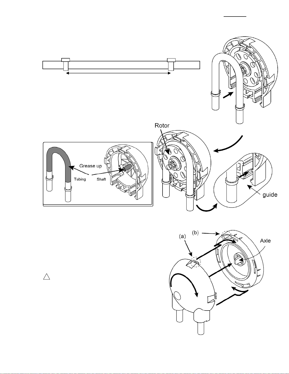
Publication #1200-04 7
4.2. Install New Tubing
4.2.1. Prepare New Tubing
1) Wrap 2 tie wraps 5 3/8” apart (136 millimeters apart) on the new Tubing.
Tie wrap knots facing the same direction
4.2.2. Install New Tubing
2) Remove Rotor
3) Add grease to the Cassette shaft and the surface of New Tubing.
( See gray area below )
4) Return Rotor to shaft of Cassette.
5) With both knots of the tubing facing the
Cassette install one knot into the guide.
6) Pull out the Rotor a little bit and place
Tubing between the Cassette and the Roller.
7) Install the other knot into the guide.
4.2.3. Install Cassette to Base
1) Rotate Rotor so that it fits into axle.
2) Attach Cassette onto Base of Pump by
placing (a) into (b).
3) Turn Cassette clockwise until it stops.
Verify that each indent of the Cassette is
matched perfectly with each marking on
the Base of Pump.
4) Prime Pump before Starting Dispense
Cycle.
!
Warning
Be careful not to be cut or injured
by the edge of the Pump parts.
5 3/8”
www.braintreesci.com Braintree Scientific, Inc. Model BS-900
Publication #1200-04 8
5. Peristaltic Tubing
Refer to last section of this Manual for tubing recommendations.
If you intend to use a long extension of tubing it is recommended that you (move the segment)
change the segment that is used in the pump regularly.
Be aware that the tubing will wear out because of friction. The rotating mechanism will also
wear out because of friction. Always lubricate rollers, shaft and tubing.
Note: The following flow rates and volumes are adjusted accordingly when the pump is
calibrated.
Tube Size Approximate Volume Dispensed Flow Rate (mL/min)
ID X OD [in] Per 1 revolution Maximum Minimum
3/16 X 5/16 2.434 mL (0.0822 US fl.oz) 904.4 0.041
1/8 X 1/4 1.211 mL (0.0379 US fl.oz) 416.6 0.019
3/32 X 7/32 0.642 mL (0.0217 US fl.oz) 238.4 0.011
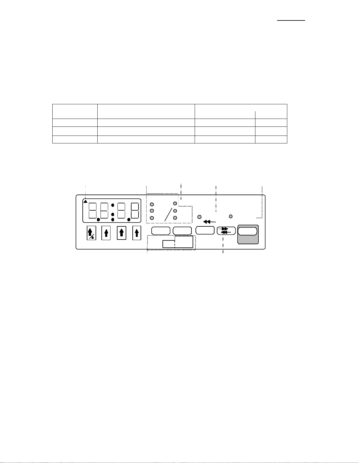
6. User Interface
Tubing ID
Inches Dispensed
mL Withdraw
min
Sec Pumping
Rate Volume Diameter Start
Program
Ph as e #
Program
Function Setup
Oz
RS-232
Indicator Units
Indicators Pumping Direction
Indicator
Volume Dispensed
Indicator
Stop
Motor
Operating
Program Entry Functions Pumping Direction Key
:
Learn
Figure 1: Front Panel
6.1. Entering Values
When applicable, values can be changed by either displaying the current value, then using the arrow keys,
or from a computer connected to the pump. The new value will be stored in the pump’s non-volatile
memory, meaning that the new value will not be lost the next time that power is applied to the pump. The
only exception is when the pumping rate is changed from an attached computer while the Pumping
Program is operating. In this case the new pumping rate will not be stored in non-volatile memory.
A displayed value can be changed by pressing the arrow keys below each digit. If the value to be changed
is not currently displayed, when applicable, press the key associated with the required value. The display
will show the setting’s current value and its units, if any.
While the current value is being changed, the units LEDs associated with the value, if any, will blink.
Except where noted, the new value is stored, and/or the selected operation takes affect, when either
If the new value is valid and different from the original value, the display will blink, indicating that the
new value was stored. Otherwise, if the value was invalid, an error message will be displayed. Pressing
any key clears the error message and restores the original value.
In general, if a parameter has 2 values, ‘off’ and ‘on’, they are represented by the numbers ‘0’ and ‘1’,
respectfully.
www.braintreesci.com Braintree Scientific, Inc. Model BS-900
Publication #1200-04 9
6.2. LCD Display
The display consists of a 4 digit reflective LCD (Liquid Crystal Diode) display. This is the general
purpose user display device for displaying numerical data, functions and parameters. The colon (:) is used
for displaying time or for separating function abbreviations from their parameter values. In the upper left
corner is a triangle that indicates valid reception of RS-232 remote communications.
6.3. LEDs
To the right of the LCD are 8 red, round, LED (Light Emitting Diode) indicators. The first 2 columns
display the units of the displayed values. Units are expressed using 1 or 2 LEDs. For instance, ‘ml / Sec’
is expressed by lighting the ‘ml’ and the ‘Sec’ LEDs.
‘Dispensed’ indicates that the displayed volume is the total ‘Volume Dispensed’ or pumped.
When ‘Pumping’ is lit (not blinking), the motor is operating, either dispensing or withdrawing. If
blinking, the motor is not operating, and the Pumping Program is paused. When the pump is restarted, the
Pumping Program will resume at the point where the Pumping Program was interrupted. When not lit
(not blinking) the pump is stopped, but the Pumping Program may be operating a pause Phase. Starting
the pump, when the Pumping Program is stopped, will start the Pumping Program from the beginning
(Phase 1).
‘Withdraw’ indicates that the pumping direction is set for withdrawing. If not lit, then the pumping
direction is set for dispensing. Also, the ‘Withdraw’ LED indicates that the “Volume Dispensed” refers to
the volume withdrawn. If not lit, the “Volume Dispensed” refers to the volume dispensed.
LED Description
Inches Tubing inside diameter in inches
mL Milliliters
min Minutes
Oz Ounces
sec Seconds
Dispensed Volume dispensed displayed
Withdraw Pumping Direction:
Lit: Withdraw
Not lit: Dispense
Pumping Lit: Motor is operating
Blinking: The Pumping Program is
paused
Not lit: The Pumping Program is
stopped or executing a pause
Phase
6.4. Arrow and Decimal Point Keys
Each of the four digits in the display is associated with the up arrow key directly below it. When
applicable, the arrow key is used to increment the value of that digit, or advance to the next selection in a
list of functions or settings.
Each press of an up arrow key will increase the digit by 1, up to 9, and then back to 0. The arrow keys
may also be held down for continuous incrementing of numbers. Some parameters, such as the RS-232
baud rate, scroll through a selection of values when the arrow keys are pressed. Other parameters have a
fixed range of values, such as some setup parameters that are either turned on or off. In these cases, the
arrow key will only scroll up to the maximum value for that parameter, then back to the minimum value.
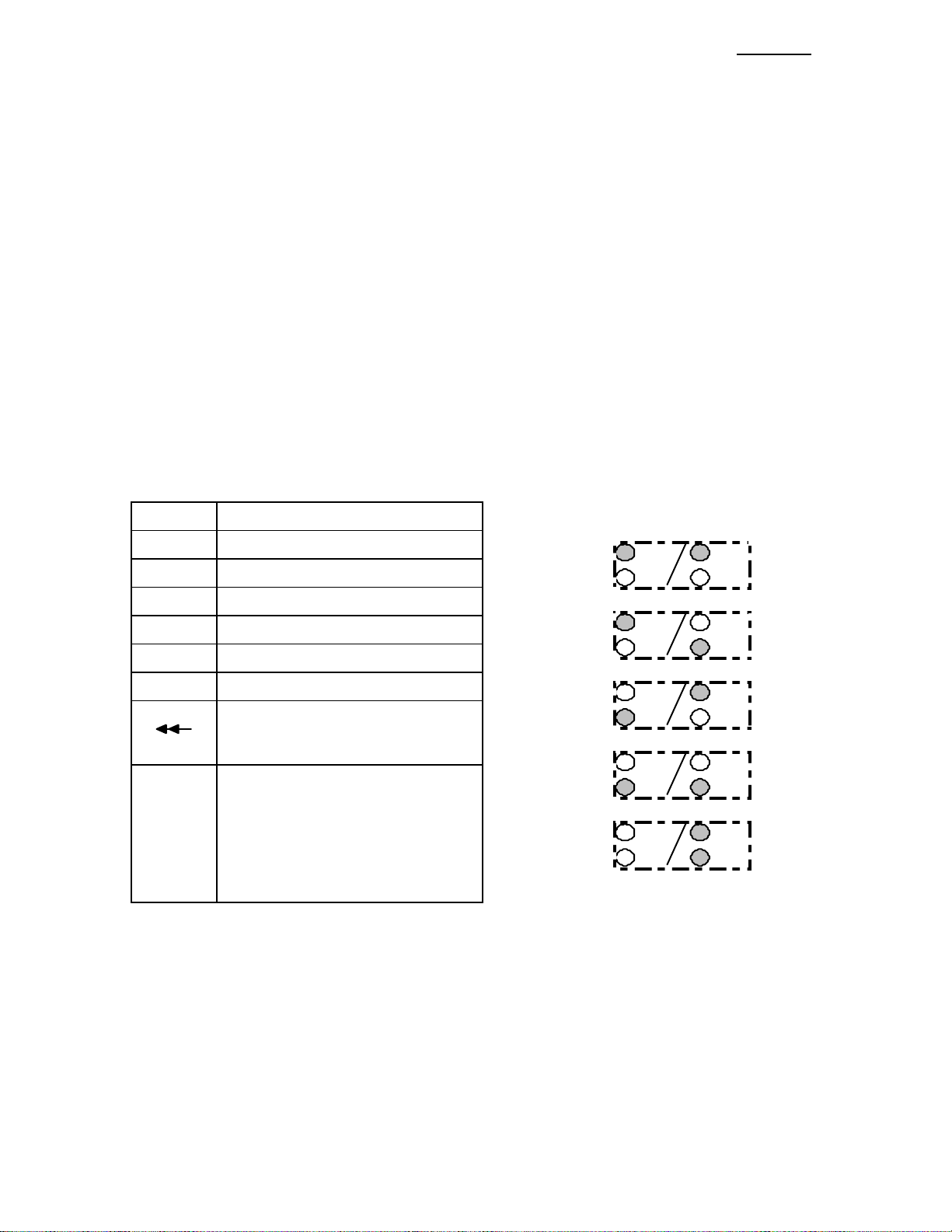
P
umping rate units are expressed using 2 LEDs:
‘ml/min’ =
mL min
Sec
Oz :
‘ml/sec’ =
mL min
Sec
Oz :
‘Oz/min’ =
mL min
Sec
Oz :
‘Oz/Sec’ =
mL min
Sec
Oz :
‘min:sec’ =
mL min
Sec
Oz :

www.braintreesci.com Braintree Scientific, Inc. Model BS-900
Publication #1200-04 10
When changing the pumping rate units, each press of any arrow key will change the units LEDs to the
next units selection.
When the display blinks, the new value is stored and takes affect. This will occur when a non-arrow key
is pressed or after a 2 second delay since the last key press.
6.4.1. Decimal Point Key
There are 4 decimal point positions on the LCD display. Each decimal point position is to the right of a
digit in the display. The last decimal point position, to the right of the right-most digit is not displayed,
indicating whole numbers with no decimal point.
To move the decimal point, simultaneously press the 2 up arrow keys under the 2 digits next to the
decimal point position. Press the same 2 up arrow keys to clear the decimal point, to display a whole
number.
Alternatively, to move the decimal point position, use the left-most arrow key / decimal point key (/).
Press and hold this key for at least 1 second and wait until the left-most digit scrolls past ‘9’ to ‘0’. While
continuing to hold this key, the decimal point will shift 1 position to the right. After the right-most
decimal point position, the decimal point will shift to the first decimal point position. Release the key
when the decimal point is in the required position.
6.5. ‘Diameter’ and ‘Setup’ Key
The ‘Diameter’ key allows the peristaltic tube inside diameter to be viewed and set. While being
displayed, the ‘Tubing ID Inches’ LED is lit. The diameter can be changed by holding the ‘Diameter’ key
while turning on power, then selecting ‘DIA’.
If the ‘Diameter’ key is pressed and held, ‘Setup’ mode will be entered. (see sec. 6.11, ‘Setup’ ).
When the Pumping Program is operating, pressing this key will display the current peristaltic tube
diameter for review. When the key is released, the display returns to its previous display.
The diameter is displayed as a fraction: 03:16 indicates 3/16” ID tubing.
6.6. ‘Rate’ and ‘Learn / Program Phase #’ Key
When the Pumping Program is stopped, except in “Program Entry Mode”, the ‘Rate’ key allows the
pumping rate to be viewed or changed. If the currently selected function allows selection of rate units,
momentarily pressing this key will switch between the ‘Rate’ display and the select rate units mode.
To change the pumping rate displayed, use the arrow keys.
While the Pumping Program is operating, pressing this key will display the current pumping rate, if
applicable. After the key is released, the pumping rate will continue to be displayed for 2 seconds. While
displayed, the current pumping rate can be changed by pressing the arrow keys. The rate units will blink
while the rate is being changed. The new pumping rate takes effect when the display blinks after a 2
second delay or when a non-arrow key is pressed. The new pumping rate is stored in the current Program
Phase.
A pumping rate of 0.0 will stop the pump. When the pumping rate is changed, if it is out of range of the
pumping rate limits, the display will show nn , where ‘nn’ indicates the currently selected Phase
Number. Pressing any key clears the message and returns to the previous pumping rate. See section 14.7,
“Tube Chemical Characteristics”, for a list of minimum and maximum pumping rates.
6.6.1. Pumping Rate Units
The pumping rate units can only be changed when the Pumping Program is not operating. If the currently
selected function allows selection of rate units (‘RATE’ function), a momentary press of the ‘Rate’ key
will enter Rate Units Change mode. The 2 LEDs representing the units will blink and the display will
show: .

www.braintreesci.com Braintree Scientific, Inc. Model BS-900
Publication #1200-04 11
Each press of any arrow key selects the next rate units, as indicated by the blinking units LEDs. When the
required rate units are blinking, press any non-arrow key or wait 2 seconds. The display will blink,
indicating the rate units are stored. The rate units are stored in the currently selected Program Phase. The
rate units can be independently set for each Phase with a ‘RATE’ function.
6.6.2. Program Entry Mode or Dispense Selection
While the Pumping Program is stopped, pressing and holding the ‘Rate’ key will enter “Program Entry
Mode” or “Dispense Selection Mode”.
If Dispense mode is enabled, the display will show the currently select dispense: nn
Otherwise, the current Program Phase number is displayed: nn
‘nn’ indicates the currently selected dispense or Program Phase.
A momentary press of the Rate or Volume key will exit return to the rate or volume display.
6.7. ‘Volume’ and ‘Program Function’ Key
When the Pumping Program is stopped, except in “Program Entry Mode”, momentary presses of this key
will switch the display between the “Volume to be Dispensed” and the “Volume Dispensed” displays, as
indicted by the ‘Dispensed’ LED.
While display “Volume to be Dispensed”, use the up arrow keys to enter a new value. Enter 0.0 to disable
the “Volume to be Dispensed” for continuous pumping. The new value is stored in the current Program
Phase or selected dispense.
If the “Volume to be Dispensed” is disabled, pressing any arrow key will change the display to 0.0. The
“Volume to be Dispensed” can now be set using the arrow keys.
While pumping, pressing and holding this key will display the current “Volume to be Dispensed”.
6.7.1. Disabling “Volume to be Dispensed”
To disable the “Volume to be Dispensed”, i.e. continuous pumping, set the “Volume to be Dispensed” to
0.0. After being stored, the display will show , indicating the “Volume to be Dispensed” is
off. In this mode, the pump will not stop at a set volume and will pump continuously until the pump is
stopped, or an “event trigger”, programmed into the Pumping Program, occurs.
6.7.2. Clearing “Volume Dispensed”
While displaying the “Volume Dispensed”, pressing and holding any up arrow key for one second will
reset the dispense and withdrawal dispensed volumes to 0.
Pressing any arrow key while displaying the “Volume Dispensed” will enter the “Set Volume Units”
mode.
6.7.3. Volume Units
With the Pumping Program stopped, and the “Volume Dispensed” displayed, as indicated by the
Dispensed LED, the volume units can be changed. Momentarily press any up arrow key. The display will
show and the volume units will blink.
Press any up arrow key to change the volume units. Wait for the time out or press any non-arrow key to
enter the setting.
NOTE: Changing the volume units changes the units for all dispenses and Program Phases.
6.7.4. Program Entry Mode
While the Pumping Program is stopped, pressing and holding the ‘Volume’ key will enter “Program Entry
Mode” or “Dispense Selection Mode”.

www.braintreesci.com Braintree Scientific, Inc. Model BS-900
Publication #1200-04 12
If Dispense mode is enabled, the display will show the currently select dispense: nn , where ‘nn’
indicates the currently selected dispense.
Otherwise, the current Program Phase function is displayed: nn
“Program Entry Mode” can be entered by pressing and holding the ‘Rate’ key. Release the key when the
display shows the current Program Phase number:, where ‘nn’ indicates the current Program Phase
number.
A momentary press of the Rate or Volume key will exit return to the rate or volume display.
6.8. Pumping Direction Key
The pumping direction key, ‘ ’, changes the direction of pumping. Pressing this key switches the
pumping direction between ‘dispense’ and ‘withdraw’, as indicated by the ‘Withdraw’ LED. When the
LED is lit, the pumping direction is ‘withdraw’, otherwise the pumping direction is ‘dispense’. The new
pumping direction is stored in the current Program Phase.
The “Volume Dispensed” is accumulated separately for dispense and withdrawal. When the pumping
direction is changed, the current “Volume Dispensed” is also changed accordingly between the dispense
and withdrawal “Volume Dispensed“ accumulations.
When the Pumping Program is operating and the “Volume to be Dispensed” is non-zero, the pumping
direction cannot be changed. Otherwise, when pumping continuously (“Volume to be Dispensed”
disabled), the pumping direction can be changed.
6.9. ‘Start’/’Stop’ Key
The ‘Start/Stop’ key starts or stops the Pumping Program’s operation. Pressing this key switches between
the Pumping Program operating and the Pumping Program paused. When the ‘Start/Stop’ key is pressed
before the completion of a Program, the motor is stopped and the Pumping Program will be paused. The
‘Pumping’ LED will then blink, indicating that the Pumping Program is paused.
Pressing this key again will resume the Program at the point it was paused. If any other key is pressed
while the Pumping Program is paused, the Pumping Program will be stopped and reset. Pressing the
‘Start/Stop’ key will then start the Pumping Program from the beginning (Phase 1).
Pressing and holding this key while starting the Pumping Program will start the prime/purge mode. Purge
will begin after the key is held for one second, and continue until the key is released. The pump will stop
after the key is released.
6.10. Dispense Selection
When in Dispense Mode, pressing and holding either the Rate or Volume keys will enter “Dispense
Selection Mode”. The display will show: nn , where ‘nn’ is the current dispense selection.
To change the current Dispense Selection, press the up arrow keys below the Dispense Selection’s digits.
The maximum Dispense number is 40. To reset to Dispense number 1, press and hold either the Rate or
Volume keys until Dispense number is 1.
Momentarily press the Rate or Volume keys to exit Dispense Selection Mode.
6.11. ‘Setup’ Key
The secondary function of the ‘Diameter’ key is ‘Setup’. While the Pumping Program is not operating,
press and hold the ‘Diameter’ key until the first setup configuration parameter, “Slow Down Mode”, is
displayed:.
n
The display will consecutively display, for about 2 seconds, each Setup Configuration parameter and its
current setting. Pressing any non-arrow key will immediately advance to the next Setup Configuration
parameter.
www.braintreesci.com Braintree Scientific, Inc. Model BS-900
Publication #1200-04 13
To change a Setup Configuration parameter, press an arrow key under the parameter’s value. To store the
new value, press any non-arrow key or wait 2 seconds. If the parameter value differs from its previous
value, the display will blink. The new parameter value will be stored and the next parameter will be
displayed.
After the last configuration parameter is displayed, the display reverts back to displaying the peristaltic
tube diameter. Any new parameter value will take affect immediately upon being stored.
6.12. Special Setup Key
While turning on power to the pump, press and hold the ‘Setup’ key to access the special setup menu. The
first menu entry “Set Tube Diameter” will be displayed:
6.13. Learn Key
While turning on power to the pump, press and hold the ‘Learn’ key to access the Learn mode menu. The
first menu entry “Learn and Repeat” will be displayed
6.14. Special Power-Up Functions
The following special functions are accessed by pressing the relevant key, while turning on power to the
pump.
6.14.1. Firmware Version Display
To display the pump’s firmware version, press the left-most up arrow key (/) while turning on
power to the pump. The display will show:
n.nn , where ‘n.nn’ is the firmware version number.
Pressing any key will clear the display.
6.14.2. Reset the Pump
To reset the pump, press the right-most up arrow key () while turning on power to the pump. The
display will show . Pressing any key will clear the display.
With a pump having as many complex features as the BS-900, it is easy for a novice user experimenting
with the pump's setup to get the pump into a 'weird' state. Performing this reset function will bring the
pump out of a 'weird' state. A default pumping rate and tubing diameter will be set.
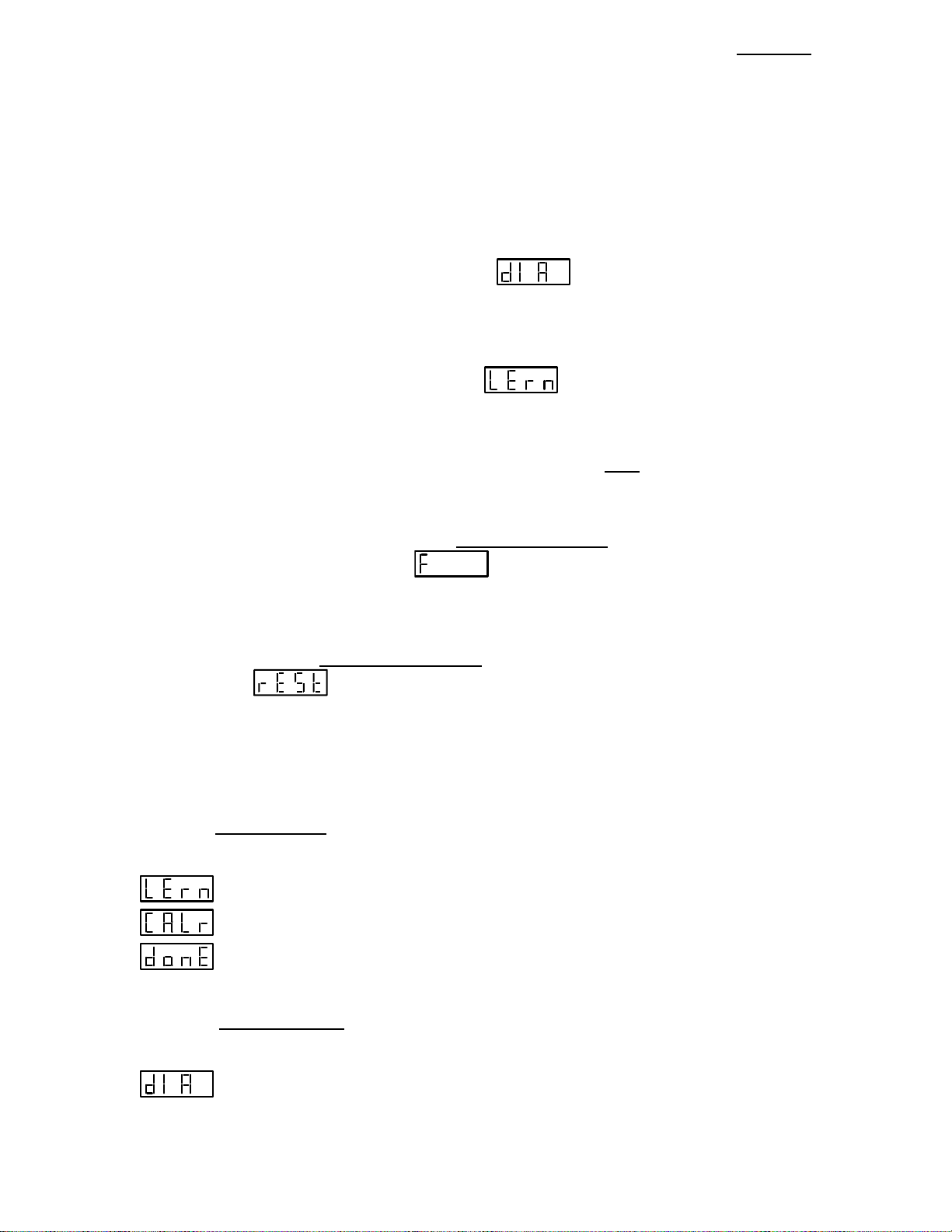
6.14.3. Learn and Calibrate Selection
Pressing the 'Rate'/'LEARN' key while turning on power to the pump will display the Learn selection
menu. Use the up arrow keys () to scroll through the selections. Press a non-arrow key or wait for the
time out to select.
Learn and Repeat Dispense
Tubing calibration
Exit without making any selection.
6.14.4. Special Setup
Pressing the ‘Diameter’/’Setup’ key while turning on power to the pump will enter the Special Setup
selection menu. Use the up arrow keys () to scroll through the selections. Press a non-arrow key or
wait for the time out to select.
Set Tubing Inside Diameter
Table of contents
Popular Water Pump manuals by other brands


Grundfos
Grundfos DPK Service instructions

HEISSNER
HEISSNER HFP5000-00 Instructions for use

Berkeley
Berkeley 6S Series owner's manual

Pentax
Pentax DP 40 Installation and operation manual

Wilo
Wilo Wilo-Drain TS Installation and operating instructions

VERDER
VERDER JEC PUMPS JRZS Series Operation and maintenance manual