Bramley 26E User manual

Service Manual
The Bramley 026E Electric/Hydraulic
Pipe Bender uses a variable speed motor
to drive a cam onto a plunger. This drives
the primary piston, sending hydraulic oil
to the main ram driving it out.
When the control valve is released the
main ram will retract via its internal
spring.
Bramley Model 26EBramley Model 26E
Electric/Hydraulic PipeElectric/Hydraulic Pipe
BenderBender
Electrical Fault
If the motor does not run check that:
• There is power to the unit.
• The plug and lead are not damaged.
The power lead, if not kept clear of the top hinging
frame or pipe being bent, can become damaged or
pulled (If the lead has been pulled, damage may not
be obvious).
The electric motor is tted with carbon brushes.
These will wear over time and require replacement.
When replacing the brushes ensure the unit is
unplugged from the power source. The brushes are
located on both sides of the motor.
To install, unscrew the plastic retaining screw on
both sides of the motor, remove the old brushes and
replace.
• Replacement Carbon Brush Set - part number
26-35
If these measures do not work, other possible motor
faults could include:
• The variable speed unit inside the handle of the
motor, or
• The armature.
These repairs should be carried out by a suitably
qualied technician.

Bramley Model 026E Electric/Hydraulic Pipe Bender
Hydraulic Fault #1
Check there is oil in the reservoir.
If there is oil in the reservoir and the unit is not
pumping, it may have been stored standing up
which can result in the unit losing its prime.
Re-prime the unit.
Hydraulic Fault #2
If the ram still fails to extend, or if the ram extends
without load but fails to extend under load (bending
pipe) all or part of the hydraulic unit will need to be
dismantled.
Remove the 2x nuts holding the gearbox/motor unit
and separate from the hydraulic unit.
Figure 1: 2x M8 nuts retaining the motor / gearbox
unit.
Undo the ller plug and drain the oil from the
hydraulic unit by tipping unit upside down.
You will see the primary cylinder/piston assembly
under the gearbox you have just removed.
The primary piston in these units reciprocates at
very high speeds with a relatively short stroke.
The primary piston pulls a fresh charge of oil from
the reservoir and pushes it out against the main
ram (when the control valve is closed).
This primary seal operates under high demand.
Wear to this seal may result in the unit losing
its prime, performing in a sluggish manner or in
extreme cases failing to operate.
Figure 2: The primary cylinder assembly tted.
Unscrew this primary cylinder assembly. Remove the
piston and inspect the seal, replace as necessary.
• Replacement seal is part of Complete Seal Kit –
part number 26-30
Under the cylinder piston assembly is a spring, lter
plate and steel ball.
Check the lter plate is at, they can deform over
time with heavy use. If the lter plate is deformed
it can be reformed simply by placing between two
pieces of steel and hammering. Note: it does not
require a lot of force to reform.
Remove the steel ball and check there is no debris
around the ball seating area.
Ret the ball and re-seat. Use a pin punch and
lightly tap the ball onto the seat.
Ret the lter plate and spring.
Check O-ring on outside of primary cylinder (replace
if necessary) and ret primary cylinder piston
assembly.
• Replacement O-ring is part of Complete Seal Kit –
part number 26-30
To re-prime the hydraulic unit.
1. Ensure the unit is horizontal.
2. Open the control valve half to one full turn.
(No more than one turn).
3. Using a small G-clamp (or similar) slowly pull
the main ram out 150mm approx.
4. Allow the ram to fully retract on its own. This
will ll a charge of oil under the primary piston
5. Close control valve and test.

Checking unit is working manually.
Rell the reservoir with oil and prime the unit as
detailed earlier. Close the control valve and test by
manually pushing primary piston with a screwdriver.
CAUTION! Do not push primary piston down too far
or apply too much force as you may dome the lter
plate. The lter plate retains the ball and controls
the stroke limits of the ball.
Hydraulic Fault #3
The main ram should move forward with every
stroke of the primary piston.
If the problem has not been resolved at this point,
the next step is to check the control valve.
Figure 3: Control value with retaining screw
removed
Loosen the control valve and then undo the retainer
screw as shown in Figure 3. This will then allow the
control valve to be removed completely.
Underneath the control valve you will nd a large
steel ball, a spring then a small steel ball at the
bottom. Note the spring has one end slightly curled
inside. This end must go back in against small steel
ball.
Check for debris and re-seat balls if necessary.
Reassemble, prime and test as described earlier.
Figure 4: Control value removed. Note large ball
visible in control valve port.
Figure 5: Control Spring removed. Note: in this
picture, the right end of the spring is slightly curled
in. This end must go against the small ball Figure 6.
Figure 6: Second smaller ball which locates on the
bottom removed
If there are no issues found in the primary
cylinder/piston assembly or control valve
the ram seal may need replacing.
To do this it is necessary to disassemble the main
ram.
First, remove the Retaining Cap at the front of the
unit. These have a 85mm spanner/socket at on
them.
The Retaining Cap nut will be very tight. They are
installed to a torque of approx. 2400Nm (1800ft/lb)
to resist the pull force against them when the unit
is in operation, and to maintain a preload tension to
prevent oil leaks from the tank seals.
Once the Retaining Cap is removed, the tank will
come away.
Between the Retaining Cap and End Collar there
will either be an aluminium washer or a O-ring in
a groove on the end of the nut (subject to age of
the machine – both available as spare parts in the
Complete Seal Kit – part number 26-30).
Continued overpage >>
New Zealand
R.R. Bramley & Co Ltd
184 Marua Road, Mt Wellington
(PO Box 14-114, Panmure)
Auckland, New Zealand.
Ph: + 64 9 579 2036
Fax: +64 9 525 0735
Email: sales@bramley.co.nz
www.bramley.co.nz
Australia
Garrick Herbert Pty Lyd
460-462 The Boulevarde (PO Box 3118)
Kirrawee, NSW 2232, Australia
Ph: + 61 2 9545 6633
Fax: +61 2 9545 4222
Email: [email protected]
www.garrickherbert.com.au
Precision and Mechanical Engineers
Machine Tool Manufacturers
Figure 7: Retaining cap undone
Next release the Main Ram from its Return Spring.
Using a vice grip or G-clamp etc, rotate the end of
the Ram counter clockwise. Turn until you can feel
no resistance to the end of the ram, this should
take between 7 to 10 turns to free.
The Ram can now be extracted from the Cylinder.
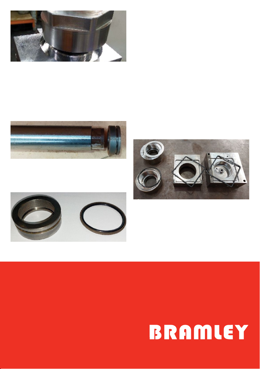
Figure 8: This pic shows the ram and collar with
seals removed.
Check the ram seal and replace if any damage is
visible.
Figure 9: Collar and ram glide seal with its
energising O-ring.
Remove the circlip off the end of the ram, slide the
piston/collar off the end of the ram.
Check O-ring condition, replace if necessary. Ret
collar, ensuring correct orientation as shown in
Figure 8.
• Replacement O-ring is part of Complete Seal Kit –
part number 26-30
To re install ram, push the ram all the way into the
cylinder and rotate the ram clockwise until you feel
spring resistance by hand. Caution: overwinding the
ram into the cylinder may cause spring damage!
Ensure the tank seals are in their slots and the
aluminium washer (if tted) is free from blemishes.
Wind nut on and tighten to specied torque.
Fill with the reservoir with oil and prime.
Check unit is working manually as described earlier
before tting the gearbox/motor unit.
Figure 10: Retaining cap with alley washer, retaining
cap with O-ring. Front nose and body with tank
seals.(Note: body does not have cylinder tted).
Popular Industrial Equipment manuals by other brands

FLENDER
FLENDER RUPER RWB Assembly and operating instructions

Siemens
Siemens SIRIUS 3TK2810-1BA4 Series operating instructions

ABB
ABB HT611072 Operation manual

Endress+Hauser
Endress+Hauser Flexdip CYA112 operating instructions

Condair
Condair Defensor OptiSorp Installation and operating instructions

arboga
arboga 75 manual


