The positioning of the steam distribution system should be determined when laying out the air-con-
ditioning system. The following points should be observed to en-sure correct humidication of the
air. The conditions must be main tained exactly to ensure that the OptiSorp system satises the
high demands made of it. A layout based on incorrect data, an unfavourable installation position or
wrong installation can result in excessive humidity with separation of condensate and therefore to
damage from water. The air duct must therefore be sealed in the area of the absorption distance and
provided with a water drainage tray with outlet. The system is preferably tted immedi ately following
the air heater (and before the cooling coils). Other installation situations require additional care. A
viewing port immediately following the system is highly recommended for installation and inspec-
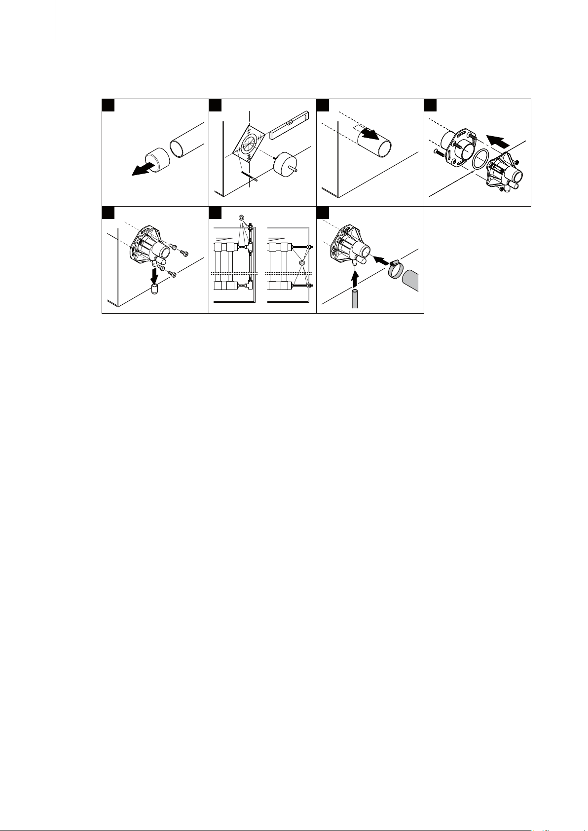
tion of operation of the instal lation. Installation of the system is always made laterally to the air ow.
With vertical air ow the nozzle tubes are tted at an angle of 20° to 30° to enable the condensate
to ow away easily.
With exception of determination of the steam absorption distance, the same basic rules apply to the
OptiSorp steam distribution system as to the standard steam distributor pipes (see installation and
operating instructions of the humidier).
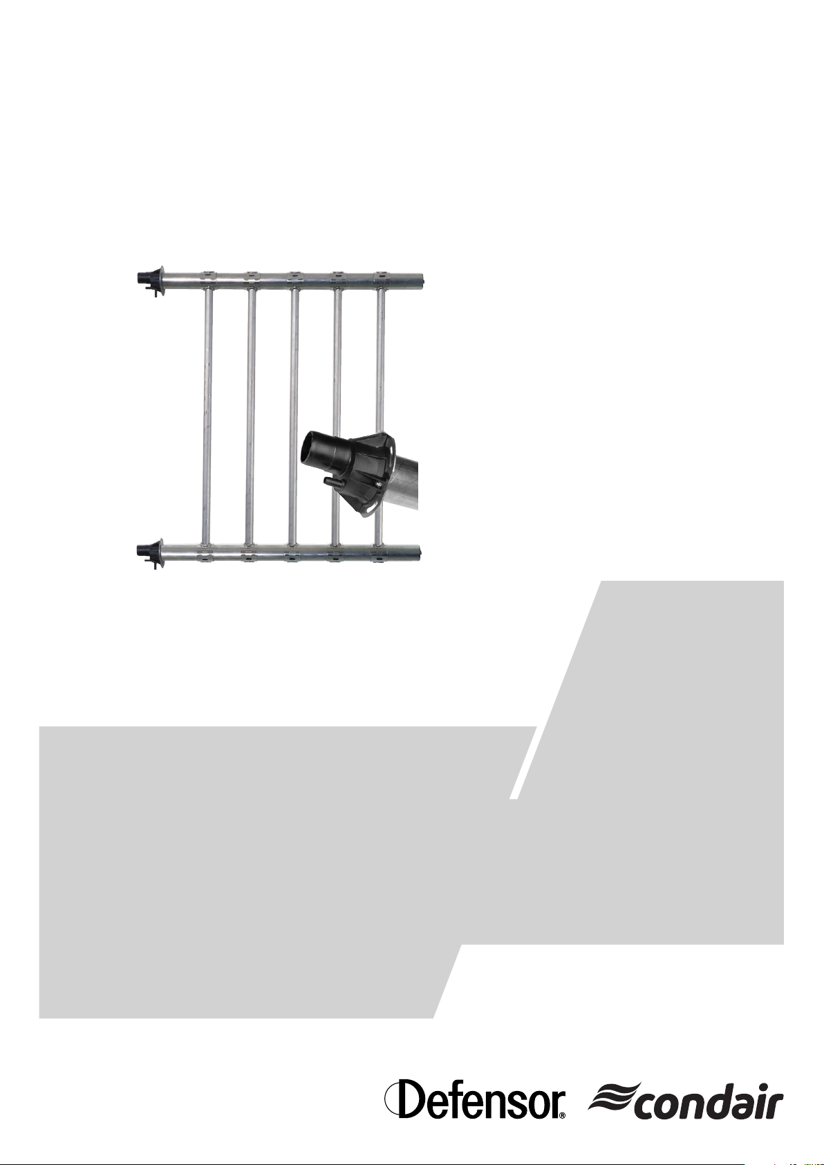
1 Notes on steam distribution system OptiSorp
The OptiSorp is made from stainless steel and high-grade plastic components. It is designed for con-
nection to the Condair and Defensor steam humidi ers. The OptiSorp steam distribu tion system is
installed directly in the air duct or in an air-handling unit. It comprises horizontal collec tor pipes and
several vertical pipes provided with steam nozzles. The OptiSorp separates the condensate from the
inlet steam and feeds this uniformly and drip-free to the air ow. In particular the steam ab sorption
distance is considerably less compared with conventional steam distribution pipes.
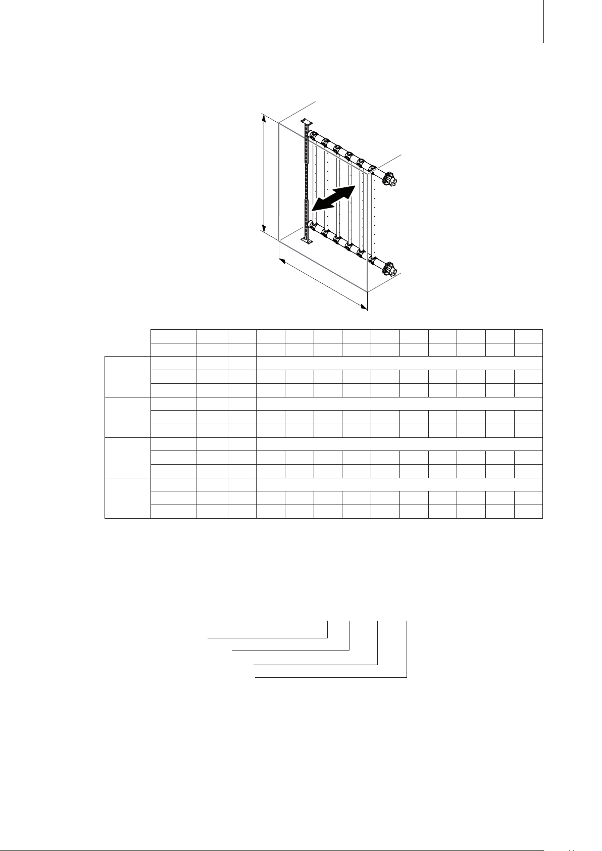
Note: To ensure a safe support of the collector pipes we recommend the use of the specially designed
support for the steam distribution system OptiSorp. The entire support is made from stainless steel
and available in four different mounting sets for duct heights ranging from 450 to 3200 mm (see
table in chapter 3.7). The mounting sets comprise all necessary parts for the correct support of a
OptiSorp system.
1.2 Positioning of the steam distribution system
1.1 OptiSorp – Steam distribution system for very short humidication distance