Edge Rebel 80 Configuration guide

Table of Contents Rebel 80
I
General Information
Section Page
1.1 Contents of the Manual ------------------------------------------------------------------------------ 1
1.2 Machine Data Plate ----------------------------------------------------------------------------------- 2
1.2 Technical Support ------------------------------------------------------------------------------------- 2
2. Technical Information
2.1 Description of the Machine ------------------------------------------------------------------------- 3
2.2 Machine Footprint ------------------------------------------------------------------------------------- 3
2.3 Specifications and Capacities ---------------------------------------------------------------------- 4
2.4 Bar stock requirements ------------------------------------------------------------------------------ 4
2.5 Safety ---------------------------------------------------------------------------------------------------- 5
2.5.1 Covers --------------------------------------------------------------------------------------------------- 5
2.5.2 Axial Shifting Switch ---------------------------------------------------------------------------------- 5
2.5.3 Lathe Door Safety ------------------------------------------------------------------------------------- 6
2.5.4 Emergency Stop Buttons ---------------------------------------------------------------------------- 6
3. Transportation and Handling
3.1 Lifting and Moving by Forklift ----------------------------------------------------------------------- 7
3.2 Lifting by Crane ---------------------------------------------------------------------------------------- 8
4. Installation of the Bar Feeder
4.1 Lathe Preparation ------------------------------------------------------------------------------------- 9
4.2 Distance from the Lathe ----------------------------------------------------------------------------- 9
4.3 Axial Shifting Device ---------------------------------------------------------------------------------- 10
4.4 Magazine Attachment --------------------------------------------------------------------------------- 12
4.5 Alignment ------------------------------------------------------------------------------------------------- 14
4.6 Anchoring the Bar Feeder ---------------------------------------------------------------------------- 15

Table of Contents Rebel 102SE
II
4.7 Electrical Connection ----------------------------------------------------------------------------------- 15
4.8 Initial Magazine Finger Adjustment ----------------------------------------------------------------- 15
4.9 Resetting the Home Position ------------------------------------------------------------------------- 18
5. Adjustments and Settings
5.1 Adjustment of Magazine Angle ----------------------------------------------------------------------- 20
5.2 Changing Bar Pushers ---------------------------------------------------------------------------------- 21
5.3 Axial Shifting ---------------------------------------------------------------------------------------------- 22
6. Control Operation and Description
6. Rebel 80 Remote Pendant ---------------------------------------------------------------------------- 23
6.1 Control Pendant Functions ---------------------------------------------------------------------------- 23
6.1.1 Status LEDs ----------------------------------------------------------------------------------------------- 23
6.1.2 Pusher Jog Buttons -------------------------------------------------------------------------------------- 23
6.1.3 V-Tray Up and Down Buttons ------------------------------------------------------------------------- 24
6.1.4 Pre Auto and Automatic/Manual Buttons ----------------------------------------------------------- 24
6.2 Sequence for Manually Changing Bars ------------------------------------------------------------ 24
6.2.1 Unload Bar from Lathe ---------------------------------------------------------------------------------- 24
6.2.2 To Load a New Bar -------------------------------------------------------------------------------------- 25
6.3 HMI (Control Panel) ------------------------------------------------------------------------------------- 25
6.3.1 Starting the Bar Feeder -------------------------------------------------------------------------------- 25
6.3.2 Setting the Measurement Standard to Inches or Millimeters --------------------------------- 26
6.3.3 Manual Screen Functions ------------------------------------------------------------------------------ 26
6.3.4 Passwords ------------------------------------------------------------------------------------------------- 26
6.3.5 Program Storage ----------------------------------------------------------------------------------------- 27
6.3.6 Forward and Reverse Jog Buttons ------------------------------------------------------------------ 28
6.3.7 Bar Off Button --------------------------------------------------------------------------------------------- 28
6.3.8 Bar On Button --------------------------------------------------------------------------------------------- 28
6.3.9 Automatic Button ----------------------------------------------------------------------------------------- 28

Table of Contents Rebel 80
III
6.3.10 Automatic Screen Functions -------------------------------------------------------------------------- 29
7. Setup Wizard
7. Setup Wizard Screens ---------------------------------------------------------------------------------- 30
8. Maintenance
8.1 Periodic Maintenance ----------------------------------------------------------------------------------- 37
8.2 Drive Belt Tension Adjustment ----------------------------------------------------------------------- 38
8.3 Lubrication ----------------------------------------------------------------------------------------------- 39
8.4 Maintenance Screens ----------------------------------------------------------------------------------- 40
9. User Parameters
9. User Parameters 1 through 8
10. Factory Parameters
10. Factory Parameters 11 through 21 ------------------------------------------------------------------ 44
11. Service Technician Parameters
10. Service Technician Parameters 22 through 42 --------------------------------------------------- 53
12. Alarms
Alarms 1 – 4 -------------------------------------------------------------------------------------------------------- 73
Alarms 5 – 13 ------------------------------------------------------------------------------------------------------ 74
Alarms 14 – 19 ---------------------------------------------------------------------------------------------------- 75
Alarms 20 – 23 ---------------------------------------------------------------------------------------------------- 76
Alarms 24 – 26 ----------------------------------------------------------------------------------------------------- 77

Table of Contents Rebel 80
IV
Alarms 27 – 29 ----------------------------------------------------------------------------------------------------- 78
Alarms 30 – 32 ----------------------------------------------------------------------------------------------------- 79
Alarms 33 – 35 ----------------------------------------------------------------------------------------------------- 80
Alarms 36 – 38 ----------------------------------------------------------------------------------------------------- 81
Alarms 39 – 41 ----------------------------------------------------------------------------------------------------- 82
Alarms 42 – 44 ----------------------------------------------------------------------------------------------------- 83
Alarms 45 – 47 ----------------------------------------------------------------------------------------------------- 84
Alarms 48 – 51 ----------------------------------------------------------------------------------------------------- 85
Alarms 52 – 70 ----------------------------------------------------------------------------------------------------- 86
Alarms 93 – 96 ----------------------------------------------------------------------------------------------------- 87
13. Electrical System
Electrical schematic table of contents ----------------------------------------------------------------------- 88
Schematic ----------------------------------------------------------------------------------------------------------- 89
14. Parts
Parts ordering information ------------------------------------------------------------------------------------- 106
Electrical components ------------------------------------------------------------------------------------------- 106
Exploded views --------------------------------------------------------------------------------------------------- 107

1. GeneralInformation Rebel 80
1
1.General Information
Please read and understand the Manual before operating the bar feeder
1.1Contents of this Manual
The bar feeder manufacturer hasprovided this manual as an integral part of themachine.
Adherence to the instructions ofthe manual will help prevent injuryto the operator and
damage tothemachine as well as helpingto realize the maximum potential of the bar
feeder andmachine tool. Particularlyimportant points ofinformationare preceded by
the followingsymbols and text:
Warning Indicates a potential danger to life or risk ofpersonal injury. Exercise
extreme caution.
Caution Indicatesa possible hazardous condition. Take precautions accordingto the
instructions followingthese warnings to help prevent injuryto personnel or damage to the
equipment.
ImportantInformation precedes special or technical information. Additional
information can be locatedbyusingthe table ofcontents ofthis manual.
Skilled Denotes operations that must be carried out byqualifiedand skilled personnel.
Other operations may be performed byqualified personnel or trained operators.
1. GeneralInformation Rebel 80
2
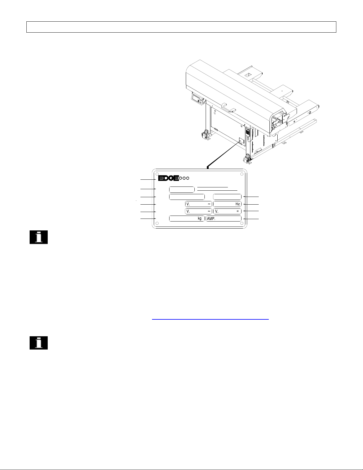
1.2 MachineData Plate
A. Nameofmanufacturer
B. Date of manufacture
C. Type(Model)
D. Serial number
E. Feedingvoltage
F. Frequency
G. Drivingvoltage
H. Control voltage
I. Machine weight
J. Amperage
Importantinformation When inquiringaboutor orderingparts pleasehave the
machine model (type) and serial number onhand.Refer to the machine dataplatefor this
information.
Technical Support
For technical support please contact the Edge Technologies Service Department
byphoneat314-692-8388 or byemail edgeservice@edgetechnologies.com
Importantinformation When calling for technical support please have the
machine model (type) and serial number onhand.Refer to the machine dataplatefor this
information.
G
I
E
C
B
A
DRIVINGVOLTAGE
FEEDINGVOLTAGE
WEIGHT
TYPE NO
11600 AdieRoad
Fax 314.692.5152
Phone 314.692.8388
www.edgetechnologies.com
edgeservice@edgetechnologies.com
Maryland Heights,MO 63043 USA
A DIVISION OF HYDROMATINC
TECHNOLOGIES
DATE
H
J
F
D
2. Technical InformationRebel 80
3
2.Technical Information
2.1Description of the Machine
The Rebel 80 is aPLC controlled, full servo automatic bar feeder designedto loadand
feedbar stock up to 4 inches in diameter.
FeaturesoftheRebel 80 include:
Mitsubishi PLC controller anddrive system.
All electrical operation, eliminatingthe need for shop air.
Storagefor spindle liners incorporated into the bar feeder base.
An axial shiftingdevice to allowthe bar feeder to be moved awayfromthe lathe spindle for
maintenance or spindle liner changes with no loss of alignment.
Soft load bar presentation to reducethe jarringeffectofheavy barsdroppinginto the channel.
Parameter driven fully automatic bar diameter adjustment andpusher thrust.
Fixed piece feeding,sub-spindle mode and push to a stopmethods ofbar feeding.
Return and wait function toreduce bar change timebyup to30%.
Touch screen controlpanel with memoryfor 36 individual jobs.
Easyto changepushers, diameters 10and19 (optional 8mm pusher available)
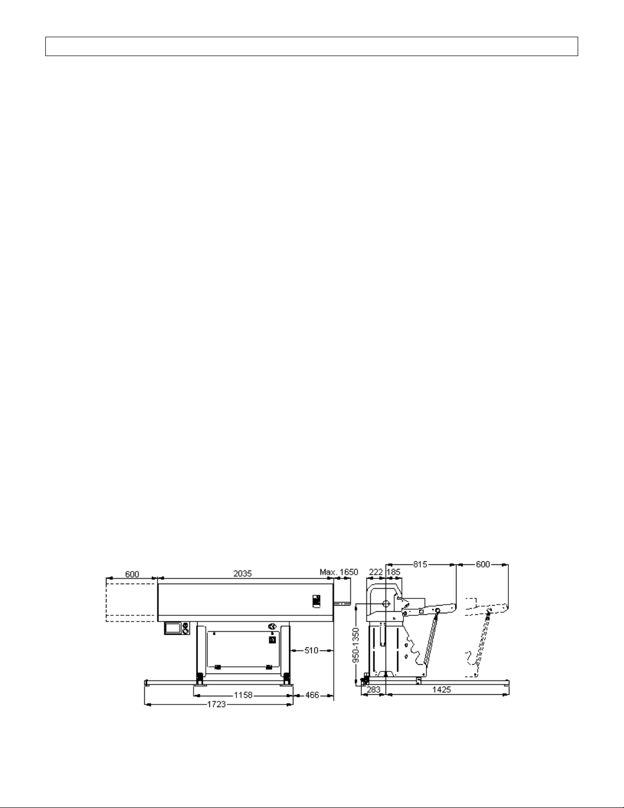
2.2Machine Footprint

2. Technical InformationRebel 80
4
2.3Specifications and Capacities
Bar diameter capacity8mmto 80mm (.315” to 3.150”)
Maximumbar length60” (NOTTO EXCEEDSPINDLE LENGTH)
Magazine rack capacity30” (60 ½” bars, 301.0” bars, 15 2.0” bars)
Bar weight 175 lbs. per bar not to exceed 1500 lbs. total
Power consumption 1 kW
Operatingvoltage 200-230VAC/60Hz– 3phase
Control voltage24VDC
Centerline height950-1350mm(37.4” to53.15”)
Machine footprint84” X48”
Machine weight 1100 lbs.
2.4Bar Stock Requirements
Material should be relativelystraight and clean. While bent stockwill not necessarilycause
problems within thelathe spindle while turning, it mayprevent loadingifbar condition is such
that thebar collides with the back of the lathe spindle or it binds while feedingintothe spindle.
Bars ofsmall diameter maynot pick up properlyfromthe magazine if theyare not straight.
Excessive chips, burrs or dirt maycause bindingwithin the spindle.
The ends ofthe bar should be relativelystraight tothe diameter of the bar to help ensureproper
positioningof the bar as it reaches thefacingpositionand tokeep the bar pusher fromslidingoff
the bar while feedingthe material.
Under no circumstances should a bar be run that extends pastthe end of the lathe
spindle!Failure to complywith this rule mayresult in injuryor death to the operator or
personnel in the vicinityof the machine and /or severe damage to the machinery!

2. Technical InformationRebel 80
5
2.5Safety
The bar feeder is designed to be safeandreliable to operate. However, the machine can be
dangerousifused improperlybyuntrainedpersonnel. Personnel should befamiliar with the
operatinginstructions ofthe equipment before usingandmust follow standard safetypractices.
The bar feeder is equipped with safetydevices to prevent accidental damage to the machine
and injuryto theoperator. These devices must notbebypassedor tamperedwith.
2.5.1 Covers
The bar feeder is supplied with covers to prevent access tomovingparts duringoperation. The
hood of the bar feeder is equippedwith a safetyswitch, S6, to place the machine inalarm ifthe
hood is not closed. The magazine cover prevents access to the material on the rackand the
bar separators.
2.5.2 Axial Shifting Switch
The bar feeder is equipped with an axial shiftingdevice to allowthe machine to bemoved away
fromthe lathe without losingthe alignment. A safetyswitch, S27,onthe axial shiftingdevice
prevents operation of the bar feeder if it is not in the proper position.

2. Technical InformationRebel 80
6
2.5.3 Lathe Door Safety
An input to the bar feeder for monitoringthelathedoor is available. Ifused, this input will
prevent movement of the bar pusher when the lathe door is open.
2.5.4 EmergencyStop Buttons
There aretwo emergencystop buttons on the bar feeder. Button ES1 is the emergencystop
button on the HMI control panel housing. Button ES2 is the emergencystop buttononthe
remote pendantcontrol. Pressingeither emergencystop button disconnects the Emergency
Stop Relay. The emergencystop relayturns offrelays MC1 and MC2 which disconnects power
fromthe servo drive and the outputs fromthe bar feeder to the lathe.
Contacts fromthe emergencystop buttons are incorporated into theinterfacewith the lathe
emergencystopcircuitto enable the lathe to be manuallyplaced into emergencystop condition
fromthe bar feeder control panel.
3. Transportation and Handling Rebel 80
7
3.Transportation and Handling
Warning Theweight ofthe bar feeder without packagingis approximately1100 lbs.
Verifythe equipment to beusedfor movingthe bar feeder is ratedto safelylift the weight ofthe
bar feeder plus the packagingmaterial. Makespecial notethat the bar feeder is top heavy and
take proper precautions.
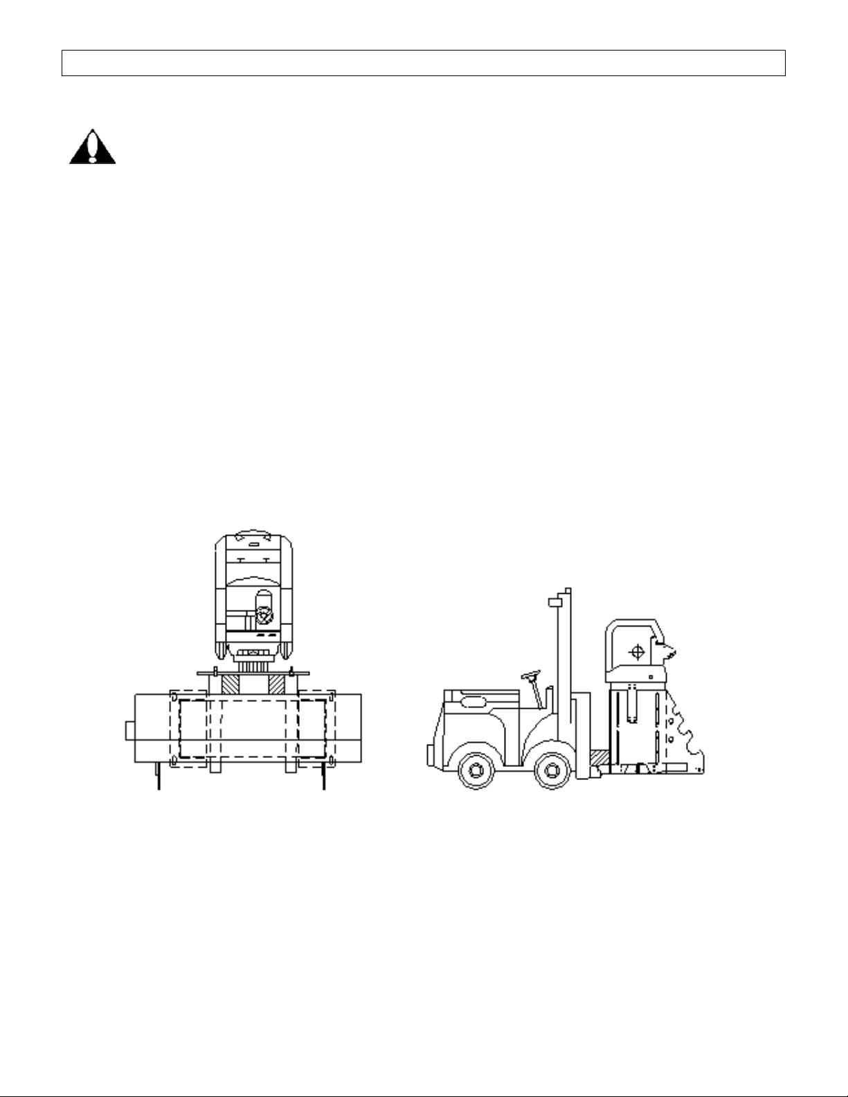
3.1Lifting and Moving byForklift
Liftingandmovingthe bar feeder byforklift is the preferredmethod ofhandlingthemachine.
Themachine shouldbe moved onlybypersonnel qualified in the operation offorklifts. The forks
must extend pastthemachine cabinet, see the drawings below. Lift themachinefromthe side
opposite the magazinemaintainingsufficient clearance fromtheforkliftmasttoavoid contact.
Care should be takento keep the load balanced. Do not lift the machine anyhigher than
necessary.

3. Transportation and Handling Rebel 80
8
3.2Lifting with acrane
Liftingandmovingthe bar feeder with a craneis possible if a forklift is not available. The crane
must be capable ofliftingat least 1,100lbs. Themachine shouldonlybe moved bypersonnel
qualifiedin the operation of the crane. Two padded liftingbars that extend at least 12inches
past the sides ofthe cabinet are required. Ideallythe liftingbars willhave eyebolts attached.
The liftingbars are placed under thepan of the bar feeder next to the electrical cabinet (see
diagram). The liftingstraps or chains should be padded to prevent damage tothe sheet metal
covers. Themachine shouldbe lifted slowlya short distance. The balance should be checked
and adjusted if necessarybefore continuing. Never lift themachinehigher than necessary.

4. Installation Rebel 80
9
4. Installation
Caution Thefollowinginstructions should be carriedoutonlybyskilled, trained
personnel. Proper alignment andinstallation is crucial to achieve optimal performanceofthe
bar feeder.Improper alignment can cause difficultyduringloading, damageto the bar feeder
and damage to the actuator andspindle bearings on the lathe.
4.1Lathe Preparation
Prior to beginningthe bar feeder installation the lathe must be properlyleveled. It is strongly
recommended that thelathebeanchored tothe floor to prevent it fromshifting.
4.2Distance FromLathe
The bar feeder shouldbe placed as closelyas possibleto therear ofthelathe while maintaining
sufficientclearance toallowthe bar feeder to be moved on the axial shiftingdevice. The area to
be occupied bythebarfeeder while shifted awayfrom the lathe should alsobe checked for
sufficientclearance. The maximumpusher extension fromthe front ofthe bar feeder is
1650mm(64.96”).

4. Installation Rebel 80
10
4.3Axial Shifting Device
The axial shiftingdevice canbeconfigured to move the bar feeder awayfrom the lathe either
parallel or perpendicular to the spindleaxis. No additional parts arerequired for changing
direction ofthe axial shift.
4.3.1 Prepare the axialtrack slide
·Begin byplacingtheaxial track slide rails on the floor.
·Locate and fasten the foot lockcross rail toend oftheaxial track rail sides that would be
the open hoodside ofthe bar feeder.
·Locate and fasten the cross rail rod between the rear ofaxial track slide rails.
·Be sureto loosen the4 axial track jack screws so there is zero preload on the floor.
·Loosen the socket head capscrews that fasten the mountinglock plate to the axial track
slide rail, then press lock plateupso there are nogaps between theaxial track bottom
thentightenscrews.
4. Installation Rebel 80
11
·Raise and supportthebar feeder to install the axial track roller slides to the baseofthe
bar feeder.
·Once axial track roller slides are installed place bar feeder onto axial track slide rails. Be
sure the roller bearings engage the slide track.
·Position bar feeder tothe full forward positionon the axial track andlock into place with
the footlock cross rail.
·It maybe necessarytoadjustlock stops on thefoot lock crossrail sothere is no
movement ofthe bar feeder once locks are engaged. Besure it does not require
excessive force to lockor unlockthe bar feeder with the foot lockrail. There should be
just enoughforce to remove bar feeder movement when locked.
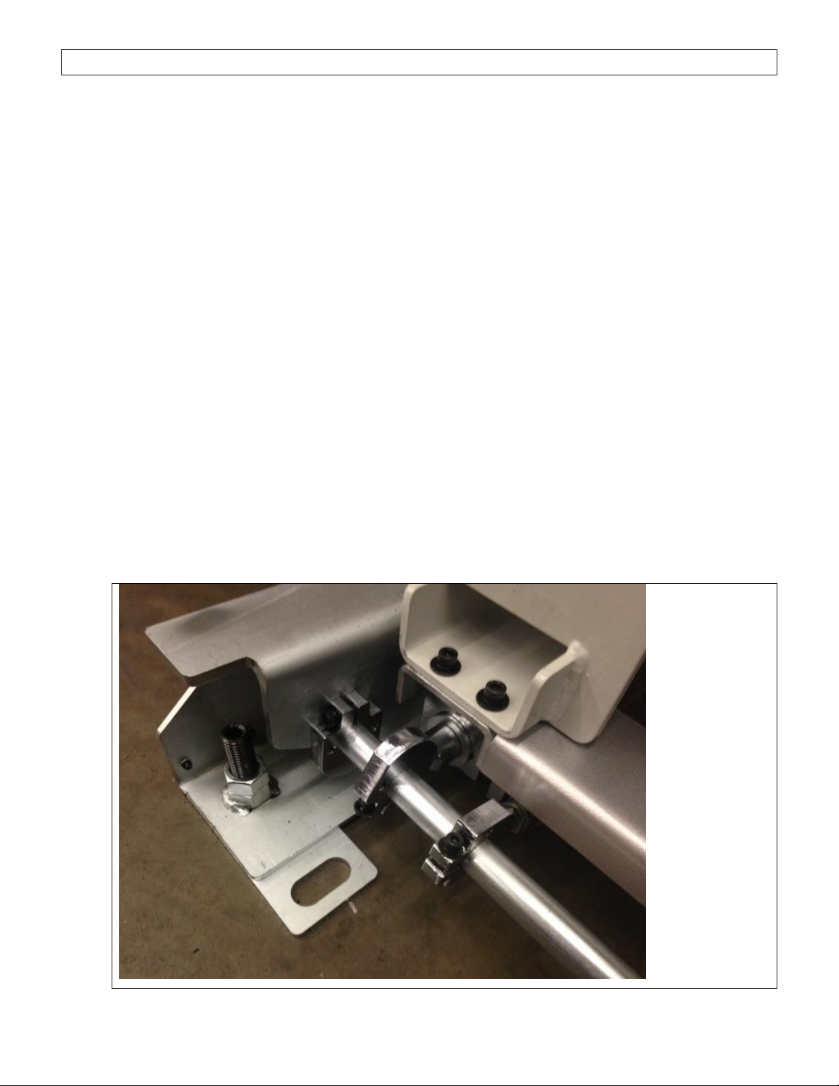
·Attachthe axial track switch to the leftfront, under side of the bar feeder. Adjustswitch
camto contact the switch roller.
·Position the final installposition of the bar feeder and axial track assemble and perform
alignment. See section4.5 for alignment procedure.

4. Installation Rebel 80
12
The axial track in position switch (LS03) is on the inside of one axial track. Thetwo latches are
mounted to the outside ofthe tracks.
The tracks should be leveled in both theXand Z axis. Keep the rails as closeas possible to the
floor.
Caution
Themagazine is heavy and will require a minimumof two people toinstall.
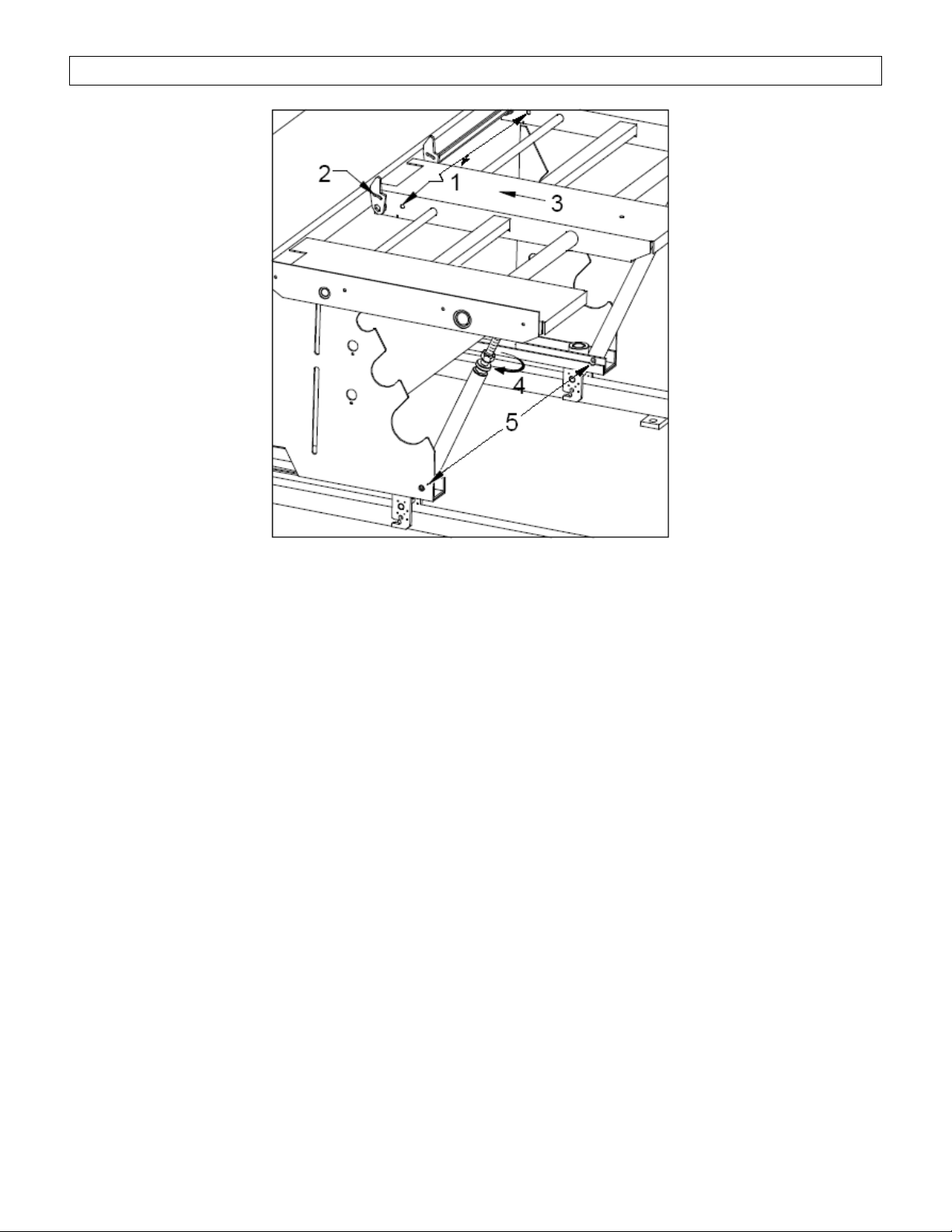
4.4Magazine attachment
Themagazine is notattached duringshipment and must be installedon site. Before liftingthe
magazine, loosen screws 2 (2 places) and remove screws 1 (3 places). Attach thetwo braces
with the bolts(5). Lift the magazine and slideit into the feeder so the center section is between
the bar lifters (2). Thread the screws ofthe braces into the nuts on the underside of the
magazine (4). Secure the magazine with the 3 screws (1). Adjust the magazine to the proper
level for the diameter and profile of the material to be run (See section 5).
Caution Magazine angle adjustment should never exceed 20 degrees or damage to
material fingers will occur.
4. Installation Rebel 80
13
4. Installation Rebel 80
14
Caution
Do notattempt tomove the bar feeder alignment when the bar stock or thebar pusher are
extendedintothe lathespindle. Damage to the bar pusher or lathespindle mayoccur.
4.5Alignment
The preferred andmost precise method of barfeeder alignment is with the Edge Technologies
Laser Alignment kit, part number EZ90001 bycontactingEdge Technologies Parts department
at (314) 692-8388 or email edgeservice@edgetechnologies.com
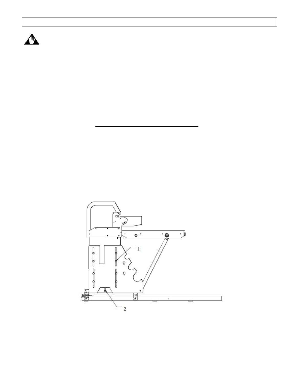
4.5.1 Alternate method of alignment
Elevation of the bar feeder is adjusted bythetwo jack screws located at thecenter of each
stand. Loosen the fourbolts securingthelegto the stand(1). Turnthe jack screw(2) to raise
or lower the bar feedercenter height. Theside-to-side alignmentis set byslidingthe bar feeder
on the floor.
·Choosea straight piece ofbar stock with a diameter asclose as possible to theboreof
the lathespindle.
·In the bar feeder parameters enter the bar length.

4. Installation Rebel 80
15
·Place the bar on the V-trayand raise the V-tray to positionusingthe trayup button.
·Slide the stock toward the spindle.
·Look into thespindlefromthe chuck end and observe theringoflight around the bar
stock. Move the bar feeder sothe ringis equal all around thestock.
·Once the bar is centered at the end ofthe spindle push itintothe lathe.
·Lookingthrough the spindle fromthe chuck the goal is tohave the bar equallyspaced
fromthe sides.
·The bar will rest on thebottom of thebore as it moves further into thespindle. This is not
a problem as longas the bar moves freely.
Bar centeredin spindle Restingon bottomofspindle
4.6Anchoring the bar feeder
When the alignment is correct the bar feeder must be anchoredto thefloor to prevent it from
movingout of position.The bar feeder is supplied with ½” diameter anchor bolts to secure the
axial track to thefloor. It is recommended to drill the holes for theanchor bolts through thefloor
ifpossibleor atleastas deep asthe anchor bolt is longso that the bolt maybe driven flushwith
the floor should themachine need tobemoved. Alignmentshould be rechecked after anchoring
the bar feeder to the floor to make sure the alignment has notchanged.
Small adjustments to the alignmentcanbemade bythe levelingnuts on the levelingfeet.

4. Installation Rebel 80
16
4.7Electrical connection
The power for the bar feeder and the input and output signals between the bar feeder and lathe
are supplied throughthe interface cable.The interfacecable is pre-wired for the lathe
application. The installer should verifythe connection to the lathe before applyingvoltage to the
system. If the lathe is not equipped with an interface connection forthe bar feeder a plugand
cables will be supplied.The lathemust support a magazine type bar feeder interface for the
machines to be connected.
Caution Failure to followthe procedure insection 4.8mayresult in damageto the
magazine feed motor and linkage.
This procedure is for the initial setup onlyand shouldnotbeperformed again unlessinstructed
to do so bythe EdgeTechnologies service department.
4.8Initial magazinefinger adjustment
·Remove anystock fromthe magazine.
·Fromthe User Level 1 screen select Maintenance screen,enter password as required.
Table of contents
Other Edge Industrial Equipment manuals


