BRANNSTROM BilgMon488 User manual

BilgMon488 Instruction Manual vAD 1(38)
BRANNSTROM SWEDEN AB
www.brannstrom.se
INSTRUCTION MANUAL
BilgMon488
15 ppm Bilge Alarm

BilgMon488 Instruction Manual vAD 2(38)
BRANNSTROM SWEDEN AB
www.brannstrom.se
1TABLE OF CONTENTS
1 Table of Contents ............................................................................................................................ 2
2 Table of validity ............................................................................................................................... 4
3 Introduction..................................................................................................................................... 5
4 Construction.................................................................................................................................... 5
5 Operation ........................................................................................................................................ 5
6 Caution ............................................................................................................................................ 5
7 Specification .................................................................................................................................... 6
7.1 General.................................................................................................................................... 6
7.2 Specific 115/230 V AC model .................................................................................................. 7
7.3 Specific 24 V AC/DC model...................................................................................................... 7
8 Installation....................................................................................................................................... 8
8.1 Mechanical .............................................................................................................................. 8
8.2 Tube arrangement................................................................................................................... 9
8.2.1 Alternative 1.................................................................................................................... 9
8.2.2 Alternative 2.................................................................................................................... 9
8.3 Electrical ................................................................................................................................ 10
8.3.1 General installation ....................................................................................................... 10
8.3.2 Fresh water flushing valve installation.......................................................................... 11
8.3.3 115/230 VAC.................................................................................................................. 12
8.3.4 24V AC/DC ..................................................................................................................... 12
9 Calibration check........................................................................................................................... 13
9.1 Schedule ................................................................................................................................ 13
9.2 Calibration certificate expiry date......................................................................................... 13
9.3 Calibration check requirements ............................................................................................ 13
9.4 Sensor unit replacement ....................................................................................................... 13
10 Operating Instructions............................................................................................................... 14
10.1 Startup sequence................................................................................................................... 14
10.2 Main menu and indication LEDs............................................................................................ 14
10.2.1 Main menu .................................................................................................................... 14
10.2.2 LEDs and indications...................................................................................................... 15
10.3 Menu system......................................................................................................................... 16
10.4 Contrast adjustment.............................................................................................................. 17
10.5 Simulation.............................................................................................................................. 17
10.6 Force automatic stopping device activation ......................................................................... 19

BilgMon488 Instruction Manual vAD 3(38)
BRANNSTROM SWEDEN AB
www.brannstrom.se
10.7 Acknowledge alarm2............................................................................................................. 19
10.8 Information menu ................................................................................................................. 20
10.8.1 Master info .................................................................................................................... 20
10.8.2 Sensor info..................................................................................................................... 20
10.9 Log ......................................................................................................................................... 21
10.9.1 Log menu....................................................................................................................... 21
10.9.2 Step log.......................................................................................................................... 21
10.10 Cleaning & test .................................................................................................................. 22
10.10.1 Clean cell (zero calibration)....................................................................................... 22
10.10.2 Check 40NTU cal (calibration check)......................................................................... 22
10.10.3 Test outputs............................................................................................................... 23
10.11 Settings.............................................................................................................................. 23
10.11.1 Valve settings (automatic stopping device) .............................................................. 23
10.11.2 Alarm2 settings (bridge alarm).................................................................................. 23
10.11.3 Autoflush feature (automatic freshwater cleaning).................................................. 24
10.11.4 Set clock..................................................................................................................... 24
10.11.5 Curro mode (Current output mode).......................................................................... 25
10.11.6 Curro 20mA cal. (Calibration of current output)....................................................... 25
10.11.7 PPM display. (Select number of decimals in ppm display)........................................ 26
10.11.8 Standby display. (Select standby notification) .......................................................... 26
11 Automatic stopping device test................................................................................................. 27
11.1 While separator is active....................................................................................................... 27
11.2 While separator is not active. ............................................................................................... 27
12 Response test ............................................................................................................................ 27
12.1 Step 1..................................................................................................................................... 27
12.2 Step 2..................................................................................................................................... 27
12.3 Alternative............................................................................................................................. 27
13 Calibration check....................................................................................................................... 27
14 Log entries................................................................................................................................. 28
15 Maintenance ............................................................................................................................. 29
16 Real Time Clock (RTC)................................................................................................................ 30
16.1 Local time .............................................................................................................................. 30
16.2 Battery replacement ............................................................................................................. 30
16.3 RTC malfunction .................................................................................................................... 30
16.3.1 Set UTC time.................................................................................................................. 31
17 Log data download via USB ....................................................................................................... 32

BilgMon488 Instruction Manual vAD 4(38)
BRANNSTROM SWEDEN AB
www.brannstrom.se
17.1 Running the software............................................................................................................ 32
17.2 Installing the VCP driver ........................................................................................................ 32
17.3 Download procedure............................................................................................................. 32
18 Spare parts list........................................................................................................................... 35
19 Troubleshooting ........................................................................................................................ 37
2TABLE OF VALIDITY
The following table describes the software and hardware versions on which this document was
based.
Doc version
Master SW ver.
Master PCB ver.
Sensor SW ver.
Sensor PCB ver.
vAA, vAB
C3
Bilgbase_I.1/
Bilgbaslv_D.1/
Bilgbasco_A
Bilgemastex K.1
B5
Bilgemon J.1
vAC
C9
Bilgbase_I.1/
Bilgbaslv_D.1/
Bilgbasco_A
Bilgemastex K.1
B5
Bilgemon J.1
vAD
D1
Bilgbase_I.1/
Bilgbaslv_D.1/
Bilgbasco_A
Bilgemastex K.1
B5
Bilgemon J.1

BilgMon488 Instruction Manual vAD 5(38)
BRANNSTROM SWEDEN AB
www.brannstrom.se
3INTRODUCTION
The BilgMon488 bilge alarm has been designed specifically for use in conjunction with 15 ppm oil-
water separator units. BilgMon488 performance meets the requirements of the International
Maritime Organisation specifications for 15 ppm bilge alarms contained in resolution MEPC. 107(49).
BilgMon488 is equipped with 2 adjustable alarms that are triggered when the oil-content of the
processed sample exceeds the set limit (1 –15 ppm, works-adjusted to 15ppm). Alarm outputs
consist of relays and indicator LEDs. Additionally a 0(4) –20 mA current output signal (corresponding
to 0 –30 ppm) is available to enable remote surveillance and recording of oil contents.
Downloading the operating log of BilgMon488 can be done through a USB-interface. This requires
driver software and cables that can be supplied on demand.
4CONSTRUCTION
BilgMon488 consists of two main parts, the MASTER unit (housing with LCD, buttons and LEDs) and
the SENSOR unit (housing with pipe fittings).
The MASTER unit contains all the electronics used for control and data storage of the bilge alarm.
Mounted in the lid of the MASTER housing is the main memory containing the bilgealarm log.
The SENSOR unit contains electronics for measuring the sample stream. The SENSOR unit also holds
the measurement calibration data. Communication with the MASTER unit is done wireless hence the
SENSOR unit is hermetically sealed and shall not be opened.
5OPERATION
Optical sensors monitors the amount of light scattered and absorbed by the oil droplets in the
sample stream. Sensor signals are processed by a microprocessor to produce a corresponding oil
content (ppm) output. The output is communicated to the MASTER unit where it is processed. The
MASTER unit takes action, such as alarm activation, logging etc., depending on the oil content and
the separator signal.
Settings that affect the behaviour of the bilge alarm are described in detail in section 10 Operating
Instructions.
Zero point calibration can be re-adjusted on site whereas full sensor calibration according to IMO-
requirements is performed by manufacturer.
6CAUTION
Do NOT remove the internal battery for more than a couple of hours (see 16.2 Battery replacement)
Do NOT open the SENSOR unit as this will invalidate the calibration.
Do NOT open the MASTER unit when it is energized. Hazardous voltages are present inside.

BilgMon488 Instruction Manual vAD 6(38)
BRANNSTROM SWEDEN AB
www.brannstrom.se
7SPECIFICATION
7.1 GENERAL
Measurement:
Oil range:
0 –30 ppm
Resolution:
0.1 ppm
Accuracy:
According to IMO MEPC.107(49)
Response time:
< 5 sec
Alarms:
Alarm 1 (automatic stopping device) delay:
0-10 sec user adjustable
Alarm 2 (annunciation) delay:
0-60 sec user adjustable1
Alarm points 1 and 2:
1-15 ppm user adjustable
Alarm hysteresis:
0.5 ppm (below alarm point)
Data storage and retrieval:
Calibration storage:
Stored in sensor housing.
IMO required data:
Stored in BilgMon488 main housing (sensor
housing may be replaced with data remaining on
board).
Data retrieval via display.
Optional data retrieval:
Via USB port.
User interface:
LCD display:
2x16 alphanumeric display
Control:
4 button keypad
Environment:
Ambient temperature range:
According to IMO MEPC.107(49), (0-55°C)
Enclosure ingress protection rating:
IP65
Installation:
Sample line inlet operating range:
Recommended: 1-2 bar (200 –300 l/h)
Maximum: 3 bar
Sample temperature:
Maximum: 50 °C
1
0-600 sec on master unit software versions before C9, shown on certificate and in “Info” menu.

BilgMon488 Instruction Manual vAD 7(38)
BRANNSTROM SWEDEN AB
www.brannstrom.se
7.2 SPECIFIC 115/230 VAC MODEL
Input/Output:
Current output:
0 –20 mA or 4 –20 mA for 0 –30 ppm
Communications:
USB serial communication (separate cable and
software)
Alarm outputs:
2 x relays (0.25A)
Clean water solenoid valve output:
1 x relay (0.5A, supply voltage)
Switch input:
1 x switch input for separator status
System and supply:
Supply:
1 A, 115 or 230 V AC, 50 –60 Hz
Power consumption electronics:
10 VA
Power consumption solenoid:
18 VA
7.3 SPECIFIC 24 VAC/DC MODEL
Input/Output:
Current output:
0 –20 mA or 4 –20 mA for 0 –30 ppm
Communications:
USB serial communication (separate cable and
software)
Alarm outputs:
2 x relays (1A)
Clean water solenoid valve output:
1 x relay (1A, supply voltage)
Switch input:
1 x switch input for separator status
System and supply:
Supply:
1.5 A, 24 V AC (50 –60 Hz) or 24 V DC
Power consumption electronics:
10 VA
Power consumption solenoid:
18 VA

BilgMon488 Instruction Manual vAD 8(38)
BRANNSTROM SWEDEN AB
www.brannstrom.se
8INSTALLATION
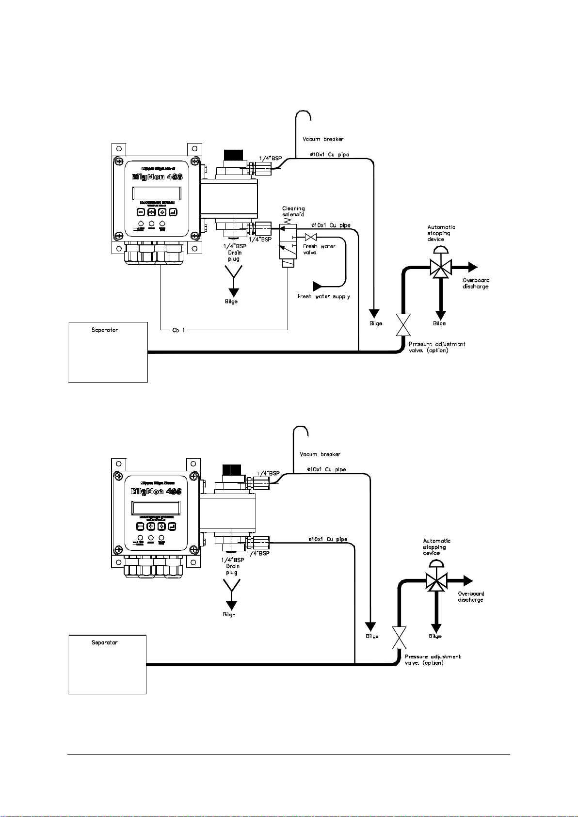
NOTE: If drain valve is fitted. It should always be closed while separator is running.
8.1 MECHANICAL
Illustration 1: Mechanical installation
BilgMon488 Instruction Manual vAD 9(38)
BRANNSTROM SWEDEN AB
www.brannstrom.se
8.2 TUBE ARRANGEMENT
8.2.1 Alternative 1
Illustration 2: Tube arrangement alt. 1
8.2.2 Alternative 2
Illustration 3: Tube arrangement alt. 2.
BilgMon488 Instruction Manual vAD 10(38)
BRANNSTROM SWEDEN AB
www.brannstrom.se
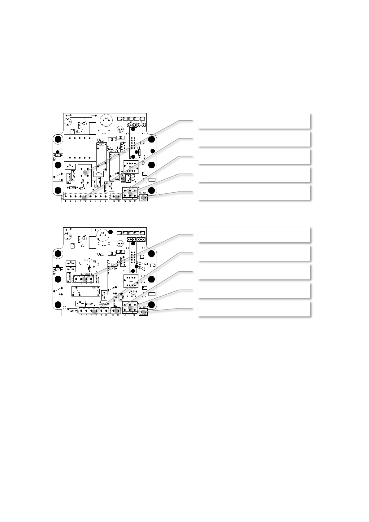
8.3 ELECTRICAL
8.3.1 General installation
Bilgmon488 is manufactured in two base models, 115/230 VAC and 24 V AC/DC. The main difference
between these two models is the base PCB of the MASTER unit.
Illustration 4: Base PCB of 115/230 VAC MASTER unit.
Illustration 5: Base PCB of 24 V AC/DC MASTER unit.
When installing the 115/230 VAC model be sure to put the voltage selection switch (SW1, Illustration
4) in the correct position (marked 115 resp. 230).
Terminals 12-14 (L8, Illustration 4) resp. 13-15 (L8, Illustration 5) are coupled and can be used for
routing of external protective earth connections.
See sections 8.3.3 and 8.3.4 for detailed information of electrical connections.
SW1: Voltage selection switch (115/230)
CN2: Terminals 1 –9
CN3: Terminals 10 - 11
L8: Terminals 12 - 13
CN1: Terminals 16 - 17
CN2: Terminals 1 - 4
CN4: Terminals 5 –10
CN3: Terminals 11 - 12
L8: Terminals 13 - 15
CN1: Terminals 16 - 17

BilgMon488 Instruction Manual vAD 11(38)
BRANNSTROM SWEDEN AB
www.brannstrom.se
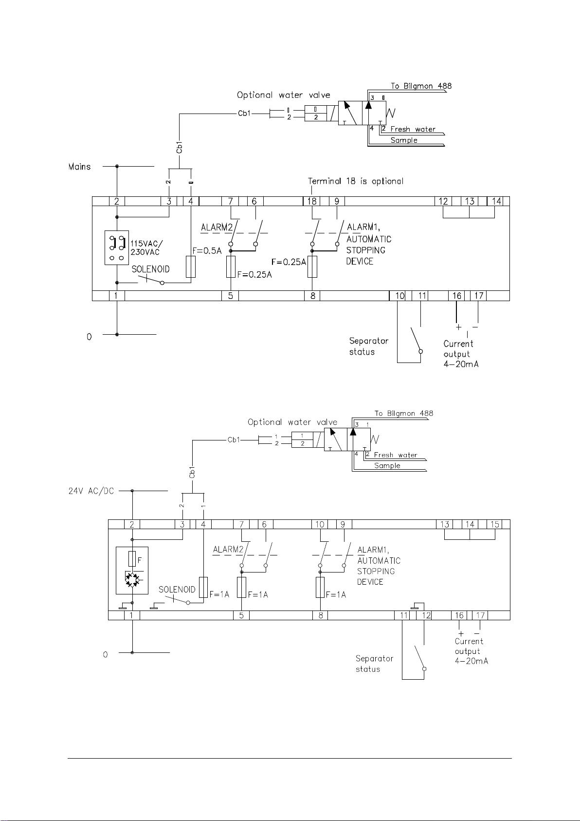
8.3.2 Fresh water flushing valve installation
This section is valid for systems using a cleaning solenoid according to Illustration 2: Tube
arrangement alt. 1 or similar installation.
115/230 VAC model: There are two coils delivered with the BilgMon
488, one to be used with 115 VAC (marked 96 V) and one to be used
with 230 VAC (marked 205 V). Be sure to install the proper one for
the chosen voltage.
24 V AC/DC model: Only one coil delivered with this model (marked
24 V).
NOTE: Both models are equipped with a cable and rectifier (in
connection plug for solenoid). The rectifier is necessary for all AC installations.
BilgMon488 Instruction Manual vAD 12(38)
BRANNSTROM SWEDEN AB
www.brannstrom.se
8.3.3 115/230 VAC
Illustration 6: 115/230 VAC electrical connections
8.3.4 24V AC/DC
Illustration 7: 24V AC/DC electrical connections
BilgMon488 Instruction Manual vAD 13(38)
BRANNSTROM SWEDEN AB
www.brannstrom.se
9CALIBRATION CHECK
9.1 SCHEDULE
Two items needs to be addressed when setting up the maintenance schedule for the BilgMon488:
Expiry date of the factory issued calibration certificate.
Occasionally a calibration check is required within the validity period of the factory issued
calibration certificate.
The following two subchapters explain how to resolve these two items.
9.2 CALIBRATION CERTIFICATE EXPIRY DATE
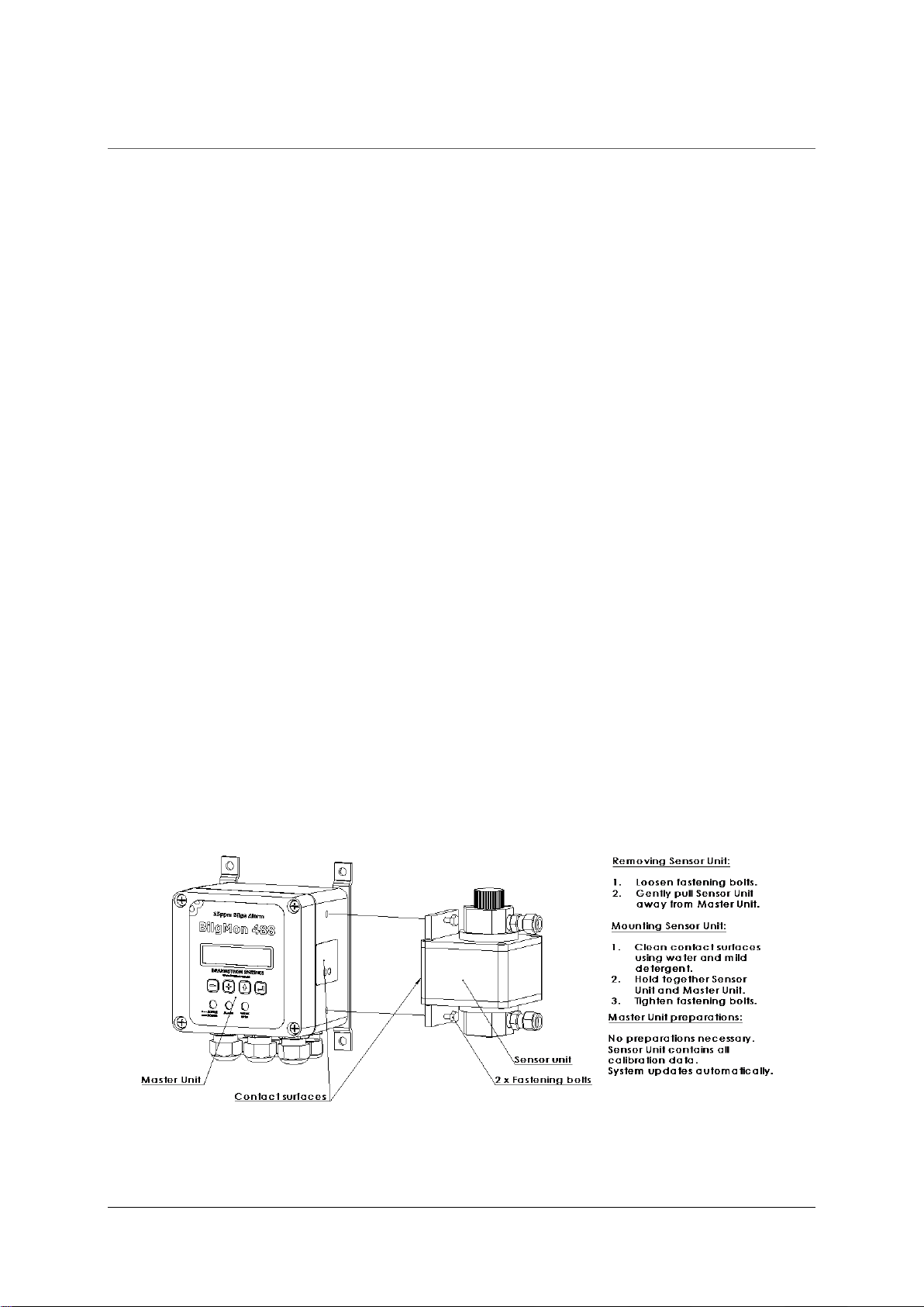
If the factory issued calibration certificate expires, the SENSOR unit must be replaced.
The SENSOR of BilgMon488 is designed to be easily replaced by the crew, see 9.4 Sensor unit
replacement. Replacement does not require any adjustments of the MASTER unit setup.
Each new SENSOR is accompanied with a new factory issued calibration certificate.
9.3 CALIBRATION CHECK REQUIREMENTS
On occasion ships may be required to perform a “calibration check” on their units. This might be
required to take place at shorter intervals than the validity period of the factory issued calibration
certificate.
Calibration check can be achieved in the following ways:
Checking calibration with a “Calibration Check Kit”.
(Requires ordering a kit or consult a service agent)
If the calibration check fails (calibration values are not within limits), a new SENSOR must be
installed.
9.4 SENSOR UNIT REPLACEMENT
Illustration 8: Sensor unit replacement procedure.

BilgMon488 Instruction Manual vAD 14(38)
BRANNSTROM SWEDEN AB
www.brannstrom.se
10 OPERATING INSTRUCTIONS
10.1 STARTUP SEQUENCE
When BilgMon488 is powered up the LCD display will show an initialization sequence.
Sequence:
1. Internal time reference (Real Time Clock, RTC) is
checked.
2. Information about unit setup is shown.
Explanation of example shown in 2.:
BilgMon 488 - Product name.
00A9 - Software version of master unit.
1dec - PPM value display precision.
CO - Current Output facility enabled.
15max - Maximum PPM level for alarm2 and automatic
stopping device settings.
1.
2.
10.2 MAIN MENU AND INDICATION LEDS
10.2.1 Main menu
After the initialization sequence is done the unit is ready for operation and the main menu will be
shown:
The main menu shows date and time followed by PPM
measurement and fresh water flushing valve selection.
Date and time is set at factory to UTC time (Coordinated Universal Time) and is displayed on the
format:
YYMMDD hh:mm:ss (YY –year, MM –month, DD –day, hh –hour, mm –minutes, ss –seconds)
PPM measurement shows the latest measurement of oil content in parts per million as reported by
the sensor unit.
Fresh water flushing valve selection shows the current selection (control output) to the optional fresh
water flushing valve:
SPL –sample from separator selected
WTR –fresh water flushing input selected
If the internal clock battery backup voltage is too low the
display will display a warning (see right) every 2 seconds.
See 30 Real Time Clock (RTC) for further information.
BilgMon 488 00A9
1dec CO 15max
RTC check:
In progress!
140612 09:10:48
PPM=12.3 SPL
WARNNG:
Change battery!

BilgMon488 Instruction Manual vAD 15(38)
BRANNSTROM SWEDEN AB
www.brannstrom.se
10.2.2 LEDs and indications
The LED lamps on the front panel indicate the status of the equipment. The straight/dashed lines
indicate if the lamps are lit continuously/flashing.
The LED lamps on the front panel indicate the status of the equipment. The straight/dashed lines
indicate if the lamps are lit continuously/flashing.
(green)
ACTIVE
POWER
Bilgmon488 is in ACTIVE mode (separator is running).
BilgMon488 is in POWER mode (menu subsystem is active).
(red)
ALARM
(no signal)
No alarm2 present.
Alarm2.
(yellow)
VALVE
OPEN
(no signal)
Automatic stopping device activated (back to bilge tank).
Automatic stopping device NOT activated (overboard valve open).
BilgMon488 Instruction Manual vAD 16(38)
BRANNSTROM SWEDEN AB
www.brannstrom.se
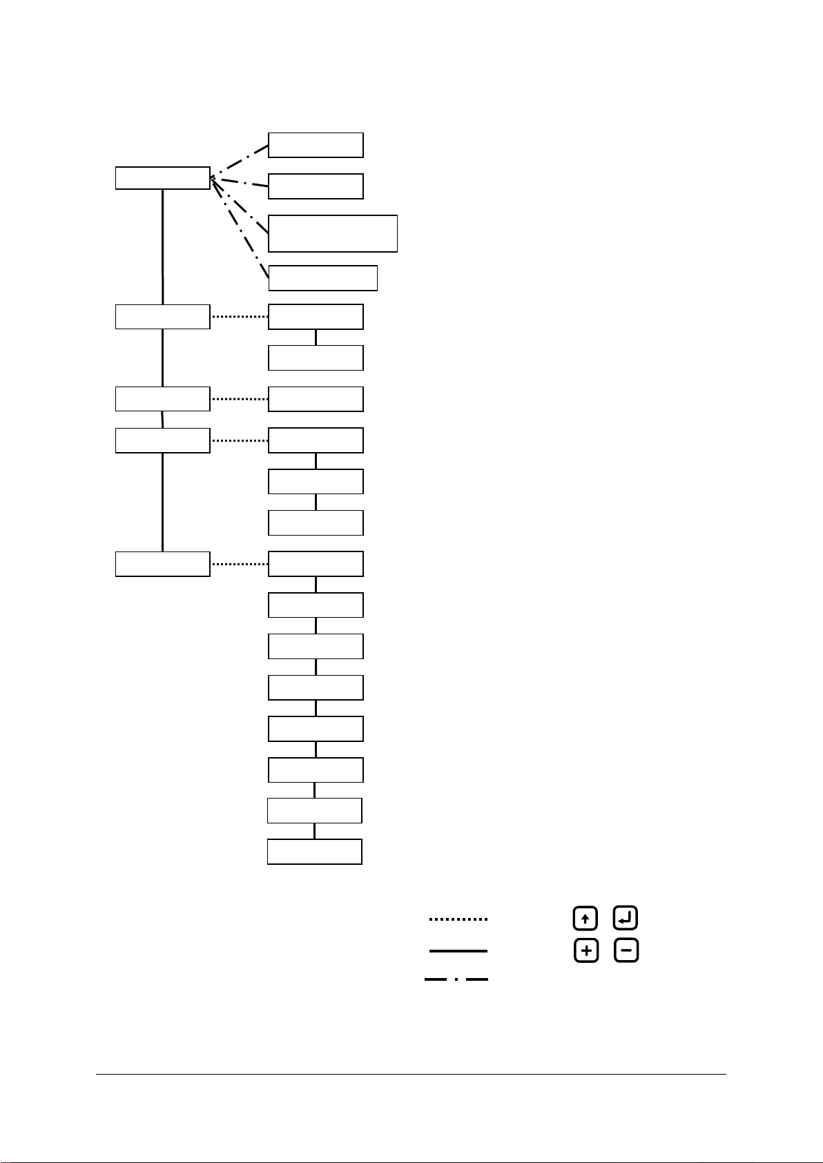
10.3 MENU SYSTEM
Illustration 9: Menu layout
Main
Info
Navigation using or
Navigation using or
Contrast
Simulation
Force automatic stopping
device activation
1) Transition only possible when BilgMon488 is in POWER mode (see 10.2).
Master info
Sensor info
Log
Step log
Cleaning & test
Clean cell
Check 40NTU cal
Test outputs
Settings
Valve
Alarm
Autoflush
Clock
Curro mode
Curro 20mA cal.
1)
1)
Adjust LCD contrast.
See 10.4 Contrast adjustment
Simulate PPM measurement and separator status.
See 10.5 Simulation
Temporarily activate automatic stopping device.
See 10.6 Force automatic stopping device activation
Show information about MASTER unit.
See 10.8.1 Master info
Show information about SENSOR unit.
See 10.8.2 Sensor info
Step, search and download the log.
See 10.9 Log
Zero calibration of SENSOR unit.
See 10.10.1 Clean cell (zero calibration)
Calibration check of SENSOR unit.
See 10.10.2 Check 40NTU cal (calibration check)
Relays and input test menu.
See 10.10.3 Test outputs
Set PPM limit and delay of automatic stopping device.
See 10.11.1 Valve settings (automatic stopping device)
Set PPM limit and delay of alarm2.
See 10.11.2 Alarm2 settings (bridge alarm)
Set interval and duration of fresh water autoflush feature.
See 10.11.3 Autoflush feature (automatic freshwater cleaning)
Adjust displayed time and date.
See 10.11.4 Set clock
Select current output logic.
See 10.11.5 Curro mode (Current output mode)
Calibrate 20mA output.
See 10.11.6 Curro 20mA cal. (Calibration of current output)
Navigation, see 10.4 - 10.7
Acknowledge alarm
Acknowledge alarm2.
See 10.7 Acknowledge alarm2
PPM display
Standby display
Select displayed number of decimals in PPM value.
See 10.11.7 PPM display. (Select number of decimals in ppm
display)
Show PPM or STANDBY at inactivity in POWER mode.
See 10.11.8 Standby display. (Select standby notification)
BilgMon488 Instruction Manual vAD 17(38)
BRANNSTROM SWEDEN AB
www.brannstrom.se
10.4 CONTRAST ADJUSTMENT
While in main menu press and hold .
With held press / to increment/decrement
contrast setting by 10%.
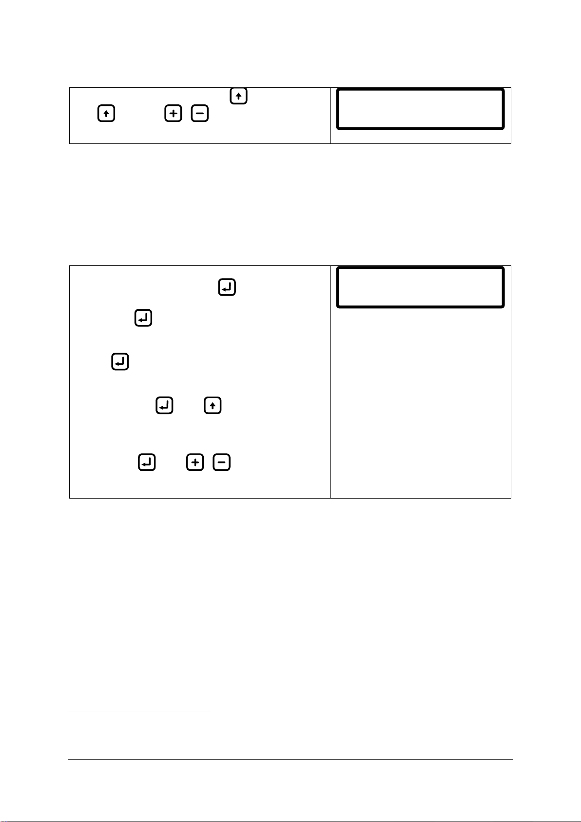
10.5 SIMULATION
The simulation menu lets user simulate the PPM input from the sensor unit as well as the separator
status input state to verify that the installation of the unit is correct and that it responds as expected
to different oil content measurements.
Simulated events will be stored in the log starting with a SIM_ON event and ended with a SIM_OFF
event.
Enter simulation menu2:
From main menu press and hold . The LCD will now
show something similar to the picture on the right.
Keep holding to stay in the simulation menu.
Leave simulation menu:
Release .
Toggle the simulated separator status input:
While still holding , press to toggle between
separator on/off (SEP_ON/SEP_OFF shown in LCD).
Increment/decrement simulated PPM value:
While holding , press / to
increment/decrement the simulated PPM value in steps
of 1.0.
2
To enter the simulation menu the BilgMon488 needs to be in POWER mode. POWER mode is when
the unit is powered but separator is not running (separator status input is open, see 8.3 Electrical).
Contrast: 010%
Simulation SPL
PPM>30.0 SEP_OFF
BilgMon488 Instruction Manual vAD 18(38)
BRANNSTROM SWEDEN AB
www.brannstrom.se
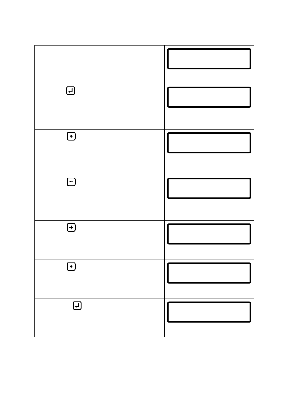
Example of simulation with explanations:
1) Start in main menu with separator off (separator
status input open).
ALARM LED –OFF
VALVE LED –OFF (no discharge)
2) Hold (do not release until step #7 in this
example).
Automatic stopping device (ASD) is now active3
and the alarm2 is not active since the separator is
not running.
ALARM LED –OFF
VALVE LED –OFF (no discharge)
3) Press to simulate that the separator starts
running (toggle to SEP_ON).
ASD and alarm2 is now active since the PPM
value is above 15 PPM and the separator is
running.
ALARM LED –ON
VALVE LED –OFF (no discharge)
4) Press repeatedly until PPM value is below
15.0 ppm (14.0 or lower value shown).
ASD and alarm2 is now NOT active since the PPM
value is below 15.0 ppm and the separator is
running.
ALARM LED –OFF
VALVE LED –ON (discharge)
5) Press repeatedly until PPM value is above
15.0 PPM (16.0 or higher value shown).
ASD and alarm2 is now active since the separator
is running and the PPM value is above 15.0 ppm.
ALARM LED –ON
VALVE LED –OFF (no discharge)
6) Press to simulate that the separator stops
running (toggle to SEP_OFF).
ASD is now active and the alarm2 is not active
since the separator is not running.
ALARM LED –ON
VALVE LED –OFF (no discharge)
7) Release to return to main menu and end
simulation.
ALARM LED –OFF
VALVE LED –OFF (no discharge)
3
The VALVE LED and the automatic stopping device output has reversed logic. Hence when VALVE LED is lit the
automatic stopping device is NOT active (overboard valve in discharge position) and vice versa.
140613 09:50:24
PPM>30.0 SPL
Simulation SPL
PPM>30.0 SEP_OFF
Simulation SPL
PPM>30.0 SEP_ON
Simulation SPL
PPM=14.0 SEP_ON
Simulation SPL
PPM=16.0 SEP_ON
Simulation SPL
PPM=16.0 SEP_OFF
140613 09:50:24
PPM>30.0 SPL

BilgMon488 Instruction Manual vAD 19(38)
BRANNSTROM SWEDEN AB
www.brannstrom.se
10.6 FORCE AUTOMATIC STOPPING DEVICE ACTIVATION
When the separator is running and the PPM value is below 15.0 ppm the automatic stopping device
can be temporarily activated by pressing and holding for approx. 2 sec.
After 10 seconds or on a press of BilgMon488
returns to normal operation.
10.7 ACKNOWLEDGE ALARM2
If separator is running (separator status input is closed, BilgMon488 in ACTIVE mode) and the PPM
value goes above 15.0 ppm the unit will generate an alarm2 (alarm2 output terminal and LED). The
alarm2 can be acknowledged
4
by pressing , or . This means that the alarm2 output
terminal will be put in no alarm position but the alarm LED on the front will still be lit.
4
Automatic stopping device output cannot be acknowledged (only alarm2 output).
Force valve
close: 10s EXIT

BilgMon488 Instruction Manual vAD 20(38)
BRANNSTROM SWEDEN AB
www.brannstrom.se
10.8 INFORMATION MENU
The information submenus will display
5
information about the MASTER and the SENSOR unit of
BilgMon488 according to examples below:
10.8.1 Master info
Cycle 0:
Menu name.
Cycle 1:
Serial number.
Cycle 2:
Software version.
Cycle 3:
Master unit lid power supply voltage. Should be approx.
5V.
Cycle 4:
RTC backup battery voltage. Should be approx. 3V. If
lower than 2.5V, replace battery ().
Cycle 5:
Internal time reference (RTC). Should be UTC time and
date (approximately).
10.8.2 Sensor info
Cycle 0:
Menu name.
Cycle 1:
Serial number.
Cycle 2:
Software version.
Cycle 3:
Factory calibration date.
Cycle 4:
Calibration check date.
Cycle 5:
SENSOR internal measurements (temperature, moisture,
voltage etc.).
5
Information is continuously cycling (cycle 0, cycle 1, … , cycle n, cycle 0, …).
Master info
Master ID:
000A-4567
Master SW ver:
00C3
Master voltage:
5V supply=5.3V
Master voltage:
RTC battery=3.0V
Master UTC:
140427 18:23:34
Se nsor info
Se nsor ID:
00 0B-4325
Se nsor SW ver:
00 B6
Se nsor date:
14 0112 13:23 :10
Ca l. checked:
14 0427 1 0:43:12
T:25.3 Dry:60
V3:3.20 V03:.312
Table of contents


