Brano Industries Aladdin II Manual

When in doubt .........
.................. Read the Manual !!!
for
Aladdin II Domestic Garage Door Operator
Setup Instruction and
Users Manual
brano industries (pty) ltd.
October 2009
COPYRIGHT C
Manual AL - N01 Version 1
brano industries (pty) ltd.
p.o. box 277, bramley, 2018, rep. of south africa.
tel +27 (011) 887-0625 fax +27 (011) 887-7616
e-mail:- [email protected] ; web:- www.brano.co.za

INDEX
Garage Door Operator Installation Manual
Section Page Description
No. No.
00 Index
00 "brano" Distribution Centres
1 Technical Specifications
1 01 Technical Specifications
2 01 Operator Parts
3 02 Control Panel Layout
4 02 Terminals and Connctions
2 Programming The Operator
1 03 Applying Power
2 03 Setting The Open And Closed
Limits
3 03 Programming The Transmitters
4 04 Setting The Force Adjustment
5 04 Installing Infra Red Safety
Beams
6 05 Setting The Auto-Close Timer
7 05 Switching The Auto-Close
Function ON and OFF
8 06 Setting The Maintenance
Flashing Counter
3 Quick Reference Guide
1 06 Quick Reference Guide
Johannesburg brano industries (pty) ltd.
Head Office:- 22 - 3rd Street, Wynberg, Sandton.
and Factory PO Box 277, Bramley, 2018, RSA.
Tel (+27) 011- 887- 0625 / 6 / 7 / 8
Fax (+27) 011- 887- 7616
Cape Town brano cape (pty) ltd
Tel 021- 552- 5350 Fax 021- 552- 5350
Pretoria brano pretoria (pty) ltd
Tel 012 - 349 - 1494 Fax 012 - 349 - 2963
Westrand brano westrand cc
Tel 011 - 760 - 5773 / 3884 Fax 011 - 760 - 5774
For more information on your nearest
agent or distribution center
please contact us on our
Share Call Number:-
08600 - 27266
Dear Installer,
Thank you for choosing a "brano industries"
garage door operator for your installation.
This operator incorporates the very latest
features associated with this type of equipment
and complies with SABS - IEC 60335 - 2 - 95
and equivalent US, European, British and
Australian standards.
Only the very best materials have been used in
the manufacture of the machine. Extensive and
punishing testing of the door operator has given
us the confidence to offer a 1 year Limited
Warranty on the unit subject to the terms and
conditions contained herein.
We trust that you will find the operator to be
everything you could want in a garage door
operator and a profitable one to work with.
If you have any queries or simply would like to tell
us of your experiences with this operator please
contact us.
Yours sincerely,
brano industries (pty) ltd.
September 2009
page inside cover

SECTION 1
Technical Specifications
“brano” door operator installation manual"
page 01
1 Technical Specifications
1.1 Power Input
220 VAC - 50Hz
1.2 Electric Motor
24 VDC
1.3 Working Temperature
-20 to 50 Degrees Celsius
1.4 Opening and Closing Force
1000 N
1.5 Receiver
On Board - 433.92 Mhz - Rolling
Code
1.6 Lamp
24V - 5 Watt - Bayonet Type
1.7 Courtesy Light Time
3 Minutes
1.8 Programming Console
Soft Touch Push Button Control
Pad with LED Display
1.9 Functions
Soft Start and Soft Stop
Adjustable Overload Sensitivity
Connection Points for Safety
Beams or Pressure Sensitive
Edges
Optional Backup Battery
Optional Auto-Close function
IMPORTANT NOTE:
The Auto-Close function should not
be activated unless Infra Red Safety
Beams have been installed. An
external power supply is needed to
supply power to the Infra Red Safety
beams, power CANNOT be drawn
from the operator PC Board.
2 Operator Parts

page 02
SECTION 1
Technical Specifications
3 Control Panels Layout
4 Terminals and Connections

page 03
SECTION 2
Programming The Operator
1 Applying Power
Ensure that the traveller is in engaged
by moving the door until a click is
heard and the traveller is connected to
the chain.
Turn the power supply to the operator
on. The courtesy light will turn on for
several seconds while the LED display
counts from “99” to “11”.
Once the auto test cycle has completed
the courtesy light will switch off and the
operator will go into standby mode.
The operator is now ready to program.
2 Setting The Open And Closed Limits
With operator engaged to the door
ensure that the door in about 150 mm
above the floor. Press and hold “SET”
until the operator displays “P1”. Press
the “SET” button to confirm setup
mode.
The display changes to show “OP”.
Use the “UP” button to jog the door all
the way to the fully open position, the
display will show “OP” throughout this
operation. When the open position is
reached, press the “SET” button.
The LED display will change from “OP”
to “CL” to show that the up limit have
been set. Using the “DOWN” button,
jog the door to the closed position. The
display will show “CL” throughout this
operation. Once the closed position is
reached press the “SET” button. The
operator will open and then close the
door automatically to complete the
setup procedure. The LED display will
show “OP” during the up cycle and
“CL” during the down cycle. Once the
setup procedure is completed the
operator will return to “STANDBY”
mode.
3 Programming The Transmitters
With the operator in “STANDBY” mode
press the “CODE” button. The LED
display will change to display “SU”.
Press and release the button on the
transmitter that you want to program.
The “SU” on the LED display will flash,
then press and release the same button
on the transmitter again. The operator
will return to “STANDBY” mode when
the transmitter is successfully
programmed in.
The operator can store 20 transmitter
codes. When the receiver memory is
full the LED display will flash “FU” to
show that the memory is full.

page 04
SECTION 2
Programming The Operator
To clear the memory press and hold the
“CODE” button for 10 seconds. During
this time the display will change to
show “SU” and once the memory is
clear the display will show “DL”.
Important Note:
Always clear the operator memory on first
installation as the all the transmitter buttons
are coded in, in the factory for testing
purposes.
4 Setting The Force Adjustment
The operator is designed to sense
obstructions under the door. The
operator will stop and reverse
direction if it is obstructed in the down
direction. If it is obstructed in the up
direction the operator stop.
The operator has 9 sensitivity levels
with “F1” being the most sensitive and
“F9” being the least sensitive. The
default setting is “F5” and it should not
be necessary to adjust this setting if the
door is properly balanced.
To adjust the force sensitivity press and
hold the “SET” button until the display
shows “P1”. Press the “UP” button
once and the display will show “P2”.
Press the “SET” button to enter setup
mode. The display will show the current
setting. To increase the sensitivity
press the “UP” button and to decrease
the sensitivity press the “DOWN”
button. When the desired sensitivity is
reached press the”SET” button and
the operator will return to “STANDBY”
mode to show that the setting is
complete.
5 Installing Infra Red Safety Beams
The operator is designed to have Infra
Red Safety beams connected as an
optional safety device. The operator
must be set up to be able to function
correctly with this device connected.
PLEASE NOTE:- An external power
source is needed for the IR Safety
Beams. If a back-up battery is installed
the operator will not close the door
when the mains power is interrupted as
the IR Safety Beams will not be
functioning. The door will have to be
closed manually. If battery back-up is a
requirement it is suggested that IR
Safety Beams are NOT fitted to the
operator.
To install the IR Safety Beams press
and hold the “SET” button until the
display shows “P1”. Press the “UP”
button until the display shows “P3”.
Press the “SET” button to enter the
setup mode.

page 05
SECTION 2
Programming The Operator
To set the auto-close function press
and hold the “SET” button until the
display shows “P1”. Press the “UP”
button until the display shows “P4”.
When the desired setting is reached
press the “SET” button. The operator
will return to “STANDBY” mode to
indicate that the setup is complete.
5 Setting the Auto-Close Timer
Important Note:-
The Auto-Close function should not be
used unless IR Safety Beams are fitted
to the operator. Brano Industries
recommends that the Auto-Close
function be disabled. Using this function
is done entirely at the risk of the
installer and the home owner. Brano
Industries cannot be held responsible
for any damage to property and or
injury to persons.
Press the “SET” button to enter the
setup mode and the display will show
the current setting. Using the “UP” and
“DOWN” buttons adjust the setting
until you reach the desired auto-close
time.
When the desired time is reached press
the “SET” button. The operator will
return to “STANDBY” mode to indicate
that the setting is complete.
7 Switching The Auto-Close Function
ON or OFF
The default setting for the Auto-Close
function is off. The function must be
turned on before the operator will close
the door automatically. To switch the
auto-close funtion “ON” or “OFF”
press and hold the “SET” button until
the display shows “P1”. Press the
“UP” button until the display shows
“P5”.
The display will show the current
setting - in the default setting “H0” the
IR Safety Beams are disabled. Use the
“UP” and “DOWN” buttons to switch
between “H0” - IR Beams disabled and
“H1” - IR Beams enabled.
“10” seconds is the minimum and
“90” seconds the maximum that the
timer can be set to.
Press the “SET” button and the display
will show the current setting. Press the
“UP” or “DOWN” button to switch
between “b0” - Auto-Close Disabled
and “b0” - Auto-Close Enabled.
When the desired setting is reached
press the “SET” button. The operator
will return to “STANDBY” mode to
indicate that the setup is complete.

page 06
SECTION 2
Programming The Operator
SECTION 3
Quick Reference Guide
8 Setting the Maintenance Flashing
Counter
The operator is equipped with
maintenance flashing counter that
enables you to set the courtesy light to
flash for 2 minutes after a preset
number of cycles have been
completed. This let the user know that
the operator needs a service. The
counter has 9 levels and each levels
accounts for 2000 complete cycles.
To set the maintenance counter press
and hold the “SET” button until the
display shows “P1”. Press the “UP”
button until the display shows “P6”.
Press the “SET” button to enter the
setup mode.
Functions
1 “P1” - Limits Settings
“OP” - Open Limit
“CL” - Closed Limit
2 “P2” - Closing Force Adjustment
“F1” - Most Sensitive
“F5” - Default Setting
“F9” - Least Sensitive
3 “P3” - Setting IR Safety Beams
“H0” - IR Safety Beams Disabled
“H1” - IR Safety Beams Enabled
4 “P4” - Setting Auto-Close Timer
“10” - 10 Seconds - Shortest Setting
“20” - 20 Seconds
“30” - 30 Seconds
“40” - 40 Seconds
“50” - 50 Seconds
“60” - 60 Seconds
“70” - 70 Seconds
“80” - 80 Seconds
“90” - 90 Seconds - Longest Setting
5 “P5” - Auto-Close ON and OFF
“b0” - Auto-Close Disabled (OFF)
“b1” - Auto-Close Enabled (ON)
6 “P6” - Setting The Maintenance
Flashing Counter
“C0” - Maintenance Flashing Disabled
“C1” - Flash after 2000 Cycles
“C2” - Flash after 4000 Cycles
“C3” - Flash after 6000 Cycles
“C4” - Flash after 8000 Cycles
“C5” - Flash after 10000 Cycles
“C6” - Flash after 12000 Cycles
“C7” - Flash after 14000 Cycles
“C8” - Flash after 16000 Cycles
“C9” - Flash after 18000 Cycles
7 “CODE” - Programming The
Transmitters
“Fu” - Memory Full
“dl” - Memory Cleared
“Su” - Search Unit - Waiting for Code to
be programmed
The display will show the current
status. Use the “UP” and “DOWN”
button to move between “C0” and
“C9”. When the desired setting is
reached press the “SET” button. The
operator will return to “STANDBY”
mode to show that the setting is
complete.
Important note:-
The counter is set in 2000 cycle increments.
“C0” - OFF
“C1” - 2000 Cycles
“C2” - 4000 Cycles Up to
“C8” - 16000 Cycles and
“C9” - 18000 Cycles.
Table of contents
Other Brano Industries Garage Door Opener manuals
Popular Garage Door Opener manuals by other brands
SVS
SVS SHR-7 FUGA operating instructions
Chamberlain
Chamberlain LiftMaster 3275C owner's manual

Chamberlain
Chamberlain RollerLift CR655MYQ Installation and operating instructions

Chamberlain
Chamberlain LiftMaster LM3800A instructions
Genie
Genie 3627436241 Assembly and installation
Chamberlain
Chamberlain GT owner's manual
jcm-tech
jcm-tech ML8NF user manual

quiko
quiko MOOVY QK-M300B Use and maintenance manual

Genie
Genie 1035 Operation & maintenance manual
Delta Electronics
Delta Electronics VFD-DD Series user manual
Overhead door
Overhead door RSX installation instructions
B&D
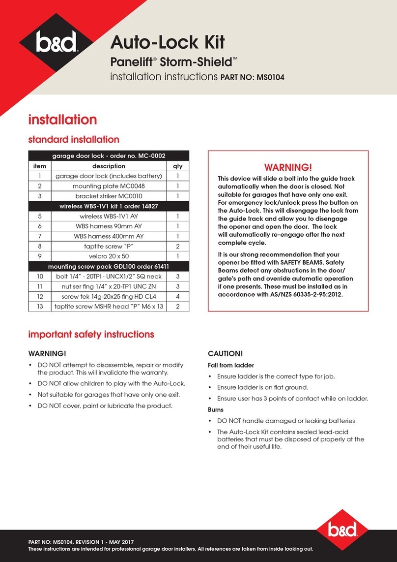
B&D Panelift Storm-Shield installation instructions
