jcm-tech ML8NF User manual

User's Manual
ML8NF
RSENS

Table of contents
jcmtechnologies
2
Maintenance
MaintenanceMaintenance
Maintenance
3
33
3
Important safety instructions for installation 3
Important safety instructions for use
4
Use of the equipment
4
Technical
TechnicalTechnical
Technical
Data
DataData
Data
5
Connection
ConnectionConnection
Connection
6
Installation
InstallationInstallation
Installation
7
Installation with support
7
Installation without support
7
Door Positioning
7
Programming
ProgrammingProgramming
Programming
8
Radio Manual Programming
8
Total Reset
8
Safety
SafetySafety
Safety
devices
devicesdevices
devices
programming
programmingprogramming
programming
9
RadioSens3 Transmitter Programming in RSEC3 Receiver
9
Adjust the sensitivity and inhibition point
9
Maneuver
ManeuverManeuver
Maneuver
programming
programmingprogramming
programming
10
Programming the door maneuver with RadioSens3 system
10
Inputs,
Inputs,Inputs,
Inputs,
outputs, dip
outputs, dipoutputs, dip
outputs, dip-
--
-switches & radio inputs
switches & radio inputsswitches & radio inputs
switches & radio inputs
11111
Regulatory
RegulatoryRegulatory
Regulatory
Data
DataData
Data
11111
EU Declaration of conformity
11

jcmtechnologies
3
Maintenance
Disconnect the power supply whenever you proceed to the installation or repair
of the control panel.
Important safety instructions for installation
•
The panel must be installed while the power is disconnected.
•
Before installing the panel, remove all unnecessary ropes or chains and disable any equipment such as
locks that is not necessary for the automatic operation.
•
Before installing the panel, check that the door is in good mechanical condition, correctly balanced and
that it opens and closes correctly.
•
Install the manual unlocking device at a height lower than 1.8m.
•
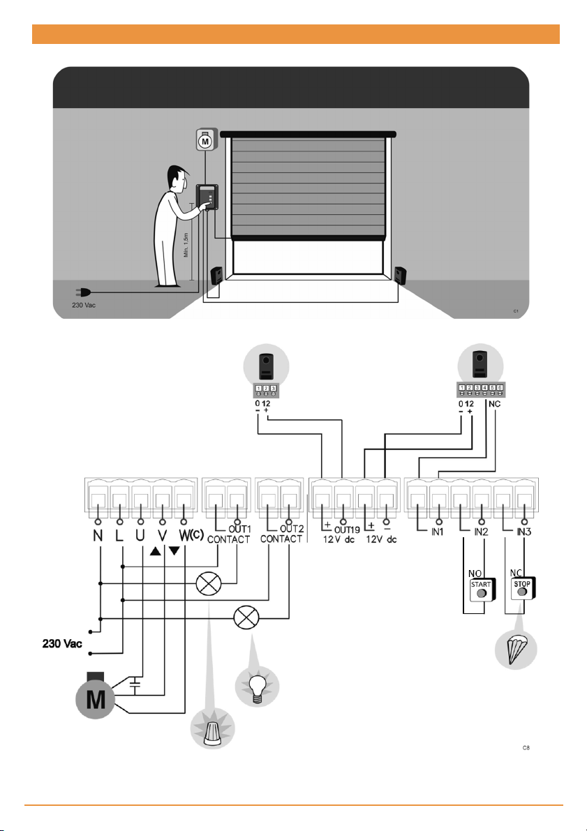
Install any permanent control next to the door away from any moving part and at a minimum height of
1.5m.
•
For permanently connected equipment, an easily accessible power disconnection device must be incor-
porated into the wiring. It is recommended that this be of the emergency switch type.
•
If the control panel is supplied without emergency stop button, this will be incorporated in the installation,
connecting it to the STOP terminal.
•
For correct use of the security edge, this must never be activated when the door is fully closed. It is wise to
install the ends of run before activating the edge.
•
This equipment can only be handled by a specialist fitter, by maintenance staff or by a suitably trained
operator.
•
To connect the power supply and motor wiring, 2.5 mm2 section terminals must be used.
•
Use protective goggles when handling the equipment.
•
Fuses must only be handled when the appliance is disconnected from the mains.
•
The instructions for using this equipment must remain in the possession of the user.
•
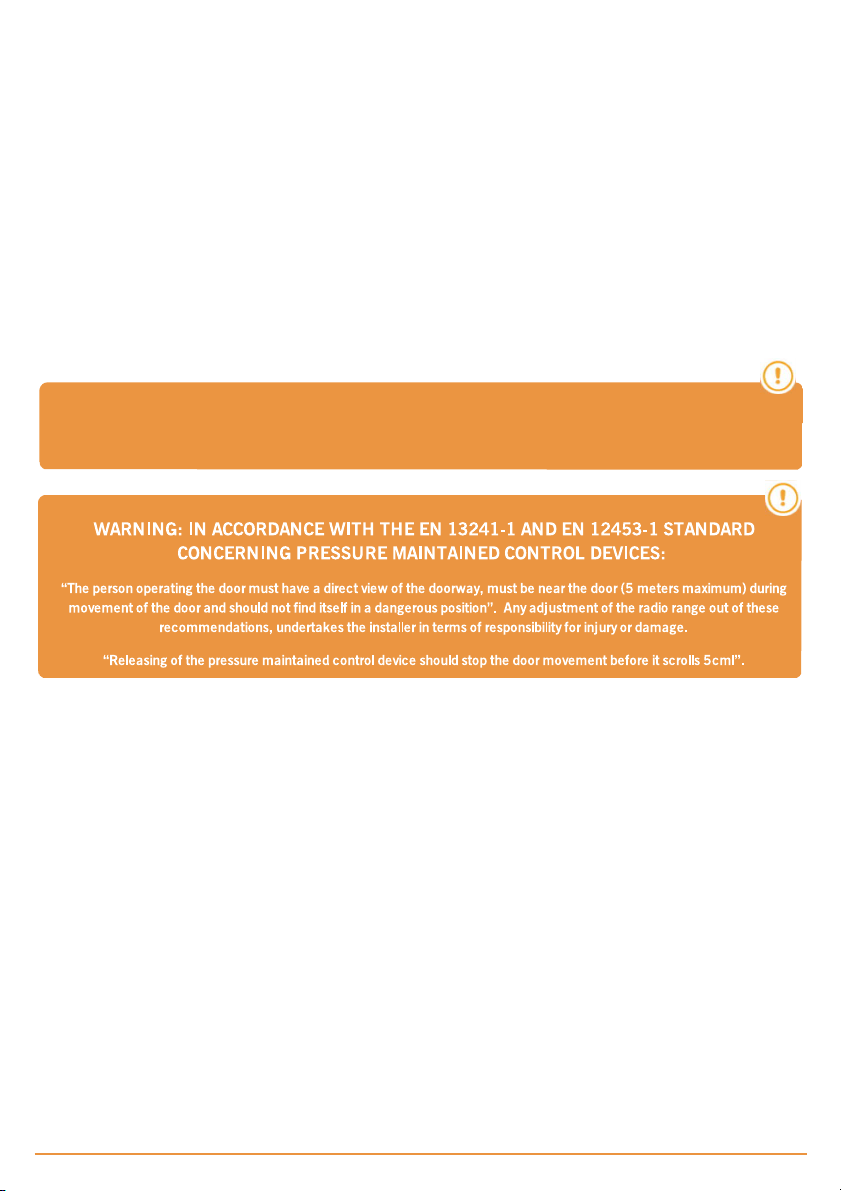
European door normative EN 12453 and EN 12445 specify the following minimum protection and
door safety levels:
-
for single-family dwellings, prevent the door from making contact with any object or limit the force of con-
tact (e.g. safety band), and in the case of automatic closing, it is necessary to complement this with a pres-
ence detector (e.g. photocell).
-
for communal and public installations, prevent the door from making contact with any object or limit the
force of contact (e.g. safety band), and complement this with a presence detector (e.g. Photocell).

Important safety instructions for use
•
Do not allow children to play with the door controls.
•
Keep the remote controls out of the reach of children.
•
Watch the door movement and keep people away until the door is fully open or closed.
•
Precaution when operating the manual unlocking device, as the door may suddenly fall due to the bad
condition of the springs or door unbalance. Details on how to use the manual unlocking device must be
provided by the manufacturer or the device installer.
•
Examine the installation frequently, especially the cables, springs and supports, to detect signs of wear,
damage or unbalance. Do not use the door if repair work or adjustments are required, as this may cause
damage.
Use of the equipment
Designed for automation of garage doors, in accordance with the general description. Not guaranteed for other uses. The man-
ufacturer reserves the right to alter equipment specifications without prior notification.
The ML8 will switch to deadman mode when safety devices are active or defective.
Therefore all controls work as 'hold-to-run' controls.
After holding for a few seconds the door will begin to move.
jcmtechnologies
4

jcmtechnologies
5
Frequency 868,35 MHz
Codification High security rolling code
Memory 27 codes (expandable to 500 codes with memory
card)
Power supply 230Vac ±10%
Maximum motor power 750W / 1200W (intensive use / residential use)
Standby /operating consumption 23mA / 43mA
Motor fuses 6A
Optional cards RSEC3 + MEM 500 + V-XPAN + TL-CARD-V
Free voltage output 2 outputs
12Vdc output 1 fix (100mA) + 1 configurable (100mA)
Manoeuvre time 1 second – 6 minutes
Operating temperature -20ºCto +55ºC
Watertighness IP32
Size 180 x 152 x 88mm
Parameter
Value
Technical Data

jcmtechnologies
6
Connection
Motor connections
:
U=OPEN (Brown)
V=CLOSE (Black)
W(c)=COMMON (Blue)

jcmtechnologies
7
Installation
Installation with support
UNSCREW EXTRACT SUPPORT DRILL WALL HANG CONTROL PANEL
SCREW
Installation without support
UNSCREW OPEN TOP DRILL WALL
Door Positioning
DOOR OPENED PRESS & HOLD CLOSE
AFTER FEW SECONDS
DOOR CLOSES
DOOR CLOSED

jcmtechnologies
8
Programming
Radio Manual Programming (Remote controls, wireless buttons, etc)
OPEN TOP
PRESS RED RPROG
PUSHBUTTON LED TURNS ON PRESS TRANSMITTER
PRESS RPROG
PUSHBUTTON LED TURNS OFF
NOTE: To program transmitters onto different channels, press and hold the red RADIO PROG pushbutton until the LED for
that channel turns on, then release the RADIO PROG pushbutton and press the transmitter.
Total Reset
OPEN TOP
END RESET
PRESS & HOLD RPROG
PUSHBUTTON BRIDGE MR SEVERAL BEEPS
PRESS RPROG
PUSHBUTTON LED TRUNS OFF

jcmtechnologies
9
Safet devices programming
On the
RadioSens3 transmitter,
the sensitivity can be adjusted.
If
sensitivity is modified, the Radi
-
oSens3 transmitter must be repro
-
grammed. You must require
the
entire system to comply with
the
safety standards to which it is sub
-
ject.
RadioSens3 Transmitter Programming in RSEC3 Receiver
PRESS PROG BUTTON OF
THE PLUGABLE CARD
RSEC3 LED TURNS ON
PRESS PROG
TRANSMITTER
ONE BEEP AND
PROGRAMMED
PRESS RPROG BUTTON
LED TURNS OFF AND END
PROG
SLIDE THE COVER TO
CLOSE
Adjust the sensitivity and inhibition point
In order to adapt the operation of the system to the irregular conditions of the floor, the equipment can be inhibited for the last
4cm at the end of the travel of the door. In the inhibition zone, obstacles will not be detected
Setting the inhibition point is optional. In case it is desired, it can be set in two ways: automatically or manually.
If the inhibition point is set automatically, put the transmitter switch SW1: 2 to ON. During the programming of the maneuver
the equipment will automatically detect the ground and set the inhibition point automatically.
If the inhibition point is set manually, proceed as defined in the control manual section: Maneuver programming: Programming
the door maneuver with RadioSens3 system.
Attention: Only one system (RadioBand3 or RadioSense3) can be programmed in the RSEC3
receiver.

jcmtechnologies
10
Maneuver programming
Programming the door maneuver with RadioSens3 system
DOOR CLOSED
PRESS WHITE PROG
PUSHBUTTON LED TURNS ON
PRESS START
PUSHBUTTON
DOOR OPENS 2 SECONDS DOOR CLOSES DOOR STOPS AUTO DOOR OPENS AUTO
DOOR STOPS AUTO AUTOCLOSE TIME
PRESS START
PUSHBUTTON DOOR CLOSES
DOOR STOPS AUTO DOOR OPENS AUTO DOOR STOPS AUTO
DOOR STOPS AUTO LED TURNS OFF END PROGRAMMING
DOOR CLOSES AUTO
*INHIBITION ZONE:
*INHIBITION ZONE:
Optionally press
START to set
inhibition point. From this point
to
the closing edge, the
safety
device will be inhibited.
The
inhibition zone must comply
with
the safety standards, it must
be
less than 40mm from the floor.

Inputs, outputs, dip-switches & radio inputs
Factory default settings. All the below can be modified with the VERSUS-PROG programming
tool. If they are modified, please ensure this manual and the sticker on the inside of the control
panel cover is updated.
For a full list of the settings & parameters available and their definitions, please refer to the
VERSUS manual.
OUTPUTS
OUT1 FLASH
OUT2 COURTESY LIGHT LEVEL
OUT19 AUTOTEST SIGNAL
DIPSWITCH OPTIONS
SW1 AUTOCLOSE
SW2 DEADMAN
SW3 PRE-FLASH
SW4 SEC. CLOSE TEST
INPUTS
IN1 SEC. CLOSE AUTOTEST (NC)
IN2 START (NO)
IN3 STOP (NC)
RADIO INPUTS
IN31 (C1) START RADIO SEC_DM
IN32 (C2) DEAD MAN CLOSE
IN33 (C3) OPEN
IN34 (C4) CLOSE
Reg
ulator Data
EU Declaration of conformity
J
J
J
JC
C
C
CM
M
M
M
T
T
T
Te
e
e
ec
c
c
ch
h
h
hn
n
n
no
o
o
ol
l
l
lo
o
o
og
g
g
gi
i
i
ie
e
e
es
s
s
s
hereby declares that the product M
M
M
M8
8
8
8N
N
N
NF
F
F
F
complies with the relevant fundamental requirements of the RED
Directive 2014/53/EU, as well as with the Machine Directive 2006/42/EC whenever its usage is foreseen; and with the
2011/65/EU RoHS Directive.
See website www.jcm-tech.com/declarations/
JCM TECHNOLOGIES, SA
C/COSTA D'EN PARATGE, 6B
08500 VIC (BARCELONA)
SPAIN
jcmtechnologies
11
This manual suits for next models
1
Table of contents
Other jcm-tech Garage Door Opener manuals
Popular Garage Door Opener manuals by other brands

Cardin Elettronica
Cardin Elettronica 24S-24L Instruction manual and users guide

Linear
Linear LCO75 installation instructions

Beninca
Beninca JM.3 manual

Chamberlain
Chamberlain LiftMaster Professional 5580 instructions

Chamberlain
Chamberlain LM80 Assembly and operating instructions

Chamberlain
Chamberlain POWER DRIVE 7520D 1/2 HP owner's manual