Brano Industries pro-alpha 2000 User guide

When in doubt .........
.................. Read the Manual !!!
for
Automatic Domestic Garage Doors
Installer's Instruction Manual
brano industries (pty) ltd.
August 1998 / April 1999 / January 2002
COPYRIGHT C
FILE:- CD10\PA2\InstalManVers3.cdr
Manual MAN - 02 Version 3
pro-alpha
door
light
brano industries
p
h
l
a
a
-
o
r
p
LRC
UTON
II
BA
C
OMAE
S
O O
O
E
S
DG
N
T
NUEM R
NAG
I
O B"
YBAO
-1
LD
UE"CN L
OURR
RN
ST O
L
L2
WPE"
PR
ER E
US
"-G
AT
T
L
OI
BR
L"AV"
M O AE8
brano industries (pty) ltd.
p.o. box 277, bramley, 2018, rep. of south africa.
tel +27 (011) 887-0625 fax +27 (011) 887-7616
"pro-alpha 2000"
electric garage door operator
i n d u s t r i e s
LUBRICATION
DO NOT USE COMMON GREASE
USE ONLY "BRANO LUBRICANT GDO-L1" OR
"LOW-TEMP LUBRIPLATE" OR "AVGREASE28"
"pro-alpha 2000"

Legal Notices
Important Notes for Dealers and Installers Regarding the
"Condition of Garage Doors and Door Operators"
1) As is the case with any installation of automatic garage door operators it is most important that the
doors are in good condition and are working in accordance with the manufacturers specifications. In
other words springs, lifting cables, pivot pins, pulleys, drums, hinges, in fact every component must
beingoodworkingorder.
2) The balance of the doors is vitally important. Before installing an automatic door operator, test the
doortomakesurethatitisproperlybalanced.
3) Ifthedoorsarenotinastateofgoodrepair,........ donotinstallanoperator!
4) If, for any reason, you fit an operator to a door which is dysfunctional or is not in sound mechanical
condition, or may be considered to be operating below the manufacturers specifications, and as a
resultthereofpersonsorpropertymaybeinjuredordamaged,......
You ! ... the dealer / installer may be held responsible and liable !
5) The responsibility for ensuring that the doors are in a condition which is acceptable for the
installation of automatic garage door operators remains solely with the dealer / installer. If the
dealerandinstallerarenotoneandthesame,thetwomaybeheldliablejointlyandseverably.
6) The law takes the view that you are the expert and therefore you should know best. You cannot
have the client indemnify you against any damages. This would be contrary to the individuals
"common-lawrights".Thelaw,now,isquiteclearinthisregard.
7) Thebestpolicyforallconcernedandespeciallyfordealers/installersissimplythis:-
Fix the door before you automate it !!!
It'sworthwhiledoing,besides,it'sgoodforbusiness!
SABS - IEC Standard No. 60335 - 2 - 95
This standard specification is now published and it's impact is being felt far and wide in the door and
gate industry. The most important aspect of this standard is that the minimum levels of safety for door
and gate operators have been set down and all installations are required to conform to this standard.
The responsibility for maintaining the standard is placed squarely on the shoulders of the installers /
dealers,inmuchthesamewayaselectriciansareresponsiblefortheworktheydo. DIY'erstakenote!
Ifsomethinggoes wrongandsomeone is injured byan automatic garage dooror gate and thecause is
deemedtobeduetoinferiorinstallationproceduresorworkmanship,orfailuretoobservethestandards
laid down, the blame will fall at the foot of the installer / dealer. The law assumes that if you install
automatic operators to doors or gates, you, the installer / dealer are familiar with the requirements
of this standard and will have satisfied yourself that the installation will comply with every
aspectofthe standard.Don'tunderestimatetheseriousnessofthesestandardsortheconsequences
thatmayresultfromanytransgressionthereof.
Be warned !!! You do so at your own risk !!!
In order to assist dealers and installers Brano Industries, from time-to-time, arranges training
courses covering the installation and maintenance of garage doors and door operators. Contact us for
details of when these courses will be run. It will be the best investment you can make in your business
andyourfuture.
Dealers & Installers ! ....... Read this section carefully !!!!
page 0 0 Inside front cover
"brano door operator installation manual"

INDEX
"pro-alpha 2000"
Installer's Manual
Section Page Description
No. No.
00 LegalNotices
01 Index
01 "brano"DistributionCentres
1 02-03 SuitableTypesofDoors
1 04 DoorsNotSuitableforAutomation
1 05 UnsafeInstallationPractices
2 06 Door Operator Terminology and
TechnicalSpecifications
3 07-08 Pre-installationPreparations
4SectionalGDOInstallation
4.1 09-10 "WorkingSpace"Tables
4.2 10-13 InstallationProcedures
ProblemInstallations-Low
Headroom
5Tip-UpGDOInstallation
14 "WorkingSpace"Tables
15 InstallationProcedures
16 ProblemInstallations-“Low
Headroom”
17 SingleAccessGarages
6 18 PCBoardConnections
19 ElectricalConnections
20 SafetyBeamConnections
7 Setting-upInstructions
21 TravelLimitSwitches
22 OverloadSensorAdjustments
8 23 OperatorFunctions
23 TestingandCommissioning
24 InformationLabelsand "Handing
Over"
9 25 ServicingandMaintenance
Lubrication
WearingParts
10 26-27 "pro-alpha2000"SpareParts
11 28-31 TroubleShootingGuide
12 32-33 TermsandConditionsofWarranty
BackCover Door Operator Equipment Details
andServiceRecord.
Johannesburg branoindustries(pty)ltd.
HeadOffice:- 22-3rdStreet,Wynberg,Sandton,RSA
andFactory POBox277,Bramley,2018,RSA.
Tel (+27)011-887-0625/6/7/8
Fax (+27)011- 887-7616
CapeTown branocape(pty)ltd
Unit 3, EXPO Centre, Koeberg Rd, ( Deliveries 35 Stella
Road), MontagueGardens,CapeTown.
Tel 021-552-5350 Fax 021-552-5350
Pretoria branopretoria(pty)ltd
Unit8-Block"B", ScientiaTechnoPark,
MeiringNaudeStr.,CSIR, Pretoria,
Tel 012-349-1494 Fax 012-349-2963
Westrand branowestrandcc
Shop No 2 Ontdekkers Centre, cor Louis Str. &
OntdekkersRd,Roodepoort,
Tel 011-760-5773/3884 Fax 011-760-5774
Bloemfontein branofreestate(pty)ltd
17MacKenzieRoad,EastEnd,Bloemfontein.
Tel 051-447-2850 Fax 011-447-7095
DearInstaller,
Thank you for choosing the "pro-alpha 2000"
garagedooroperatorforyourinstallation.
The"pro-alpha 2000" incorporates the verylatest
features associated with this type of equipment and
complies with SABS - IEC 60335 - 2 - 95 and
equivalent US, European, British and Australian
standards.
Only the very best materials have been used in the
manufacture of the machine. Extensive and
punishing testing of the door operator has given us
the confidence to offer a 3 year Extended Warranty
on the unit subject to the terms and conditions
containedherein.
We trust that you will find the "pro-alpha 2000" to
be everything you could want in a garage door
operatorandaprofitableonetoworkwith.
If you have any queries or simply would like to tell us
of your experiences with the "pro-alpha 2000",
pleasecontactus.
Yourssincerely,
branoindustries(pty)ltd.
July1999 / October2001/February2004
page 01
"brano door operator installation manual"
i n d u s t r i e s

1.4.1 "Trackless" Type Tip-up Door
With "Pantograph" Mechanism
"SPRING BALANCED" TIP-UP DOOR
Fig No. 3
Path of Door
SECTION 1
Suitable Types of Garage Doors
page 02
1.1 INTRODUCTION
First it is necessary to identify the type of door that is
to be automated. The most common types of
domesticgaragedoorsare:-
1.1.1 SectionalOverheadDoors.
1.1.2 One Piece "Tip-Up" Doors with Jamb
MountedDoorHardware,(tracklesstype).
1.1.3 One Piece "Tip-Up" type Doors (with
"overheadtrack").
1.1.4 One Piece "Pivot" type Tip-Up Doors,
(tracklesstype doors).
1.1.5 One Piece "Tip-Up" Counterweight
Balanced type Doors, ( vertically tracked
typedoors ).
1.1.6 Steel Roll-Up type Doors, ( flexible curtain
typedoors).
TakeNote:-
"Vertically” tracked Tip-Up doors, ( e.g.
Counterweight" Balanced types ), and "Steel
Roll-Up" type doors both require the assistance
of special "adaptor" kits in order to be
automated.Consultyour dealerforadvice.
Refer to the specific instructions for the
typeofdooryouwishtoautomate.
1.2 InspectionOfTheDoor
Inspect the garage door for signs of damage or
wornorfaultycomponents.
Repair the door as necessary !
TakeNote:-
It is very important that the door be in a
state of good repair and in proper working
order.
Do not automate a door that is not in good
working order. Should persons be injured
or property be damaged by a door that is
considered to be in a condition that is
below the specifications of the
manufacturer, then you, the installer /
dealer may be held jointly and severably
responsibleandliable.
Door with "Torsion" Type Springs
Door with "Tension"
Type Springs
Fig No. 1
Path of
Door
Door in "Open"
Position
Door
Track
Note:-
Torsion springs are normally
positionedabovethedoor.
Fig No. 2
1.3 Door Type 1
SECTIONAL TYPE DOORS
1.4 Door Type 2
“ONE-PIECE" TIP-UP TYPE DOORS
"brano door operator installation manual"
i n d u s t r i e s

1.5.2.1 VERY IMPORTANT NOTE:-
This type of door can only be automated
with the aid of a special adaptor system,
viz., the "Vertical Track Adaptor Kit". When
fitted with a "VTAK" system, the "built-in"
overload sensors of the door operator,
regardless of make or model, may be
compromised to the extent that local safety
standards may not be complied with.
SABS-IEC Safety Standards preclude the
use of this system for the automation of
domesticgaragedoors.
Check with your local operator dealer for
moreinformation.
IMPORTANT NOTES ON THE
CONDITION OF GARAGE DOORS
Nodoorshouldbeconvertedtoautomatic
operation unless it is in good working
order.
Before installing an automatic door
operator, inspect the door for signs of
worn, damaged or missing parts and
repair or replace as necessary. Test the
operation of the door to make sure that it
isproperlybalanced.
Pay particular attention to the springs.
Domestic garage door springs should be
replaced after every 10 000 operating
cycles, ( or approximately 4 to 5 years of
normalusage).
Fig No. 7
Steel "Roll-Up" Type Door
"One-piece" flexible
steel curtain.
"Stationary" Shaft
Door Roll
COUNTER-WEIGHT BALANCED
"PIVOT" TYPE DOORS
1.4.2 "Trackless" Type Tip-up Door
With "Horizontal Pivot"
Fig No. 4
Floor
Level
Lintel
Ceiling
"High-Rise"
Point of Door Path of Top
of the Door
Pivot
Bearing
Counter-
Weight
page 03
1.5.1 "Inclined Track" Tip-up Door
With "Pantograph" Mechanism
Track
Roller
Angled
Track
Fig No. 5
Spring
1.5 Door Type 3
"ANGLED TRACK" TIP-UP TYPE DOORS
Fig No. 6
Counter-
Weight Vertical
Guide Track
Guide
Roller
1.5.2 Door Type 4
"VERTICAL TRACK" TIP-UP TYPE DOORS
1.6 Door Type 5
“ROLL-UP" TYPE DOORS
“brano“ door operator installation manual"
Read note 1.5.2.1

Fig No. 8
Fig No. 9
SECTION 1.7
Doors Which Are Not
Suitable For Automation
Read this section carefully !
For reasons of safety, certain doors should not
be automated. One door in particular fails to
comply with the safety standards set out in
SABS/IEC 60335-2-95
This door is commonly referred to as a "Tip-In"
or"Cam-Spring"typedoor.
DISTINGUISHING FEATURES
A "one-piece" type door which has a "vertical"
guidetrack. The distinguishingfeatureofthe door is
theplacementoftheGuideRoller.
The Guide Roller is positioned at, or close to, the
bottom-most corner of the door panel. The effect of
this arrangement is that it causes the door to open
completelytotheinsideofthegarage.
At no stage during the opening or closing cycle
does any part of the door pass through or
protrudefromtheopening.
Whenthedoorisfullyopen,theentiredoorremains
completely insideofthegarage.
Thesedoors were intended for use in openingsthat
haveroundedor"arched"shapesandweresoldas
acheaperalternativetoSectionaltypedoors.
All warranties, whether stated or
implied, shall, "ipso facto", be
rendered null and void if “Brano”
products are fitted to such types of
doors.
Do not automate this
type of garage door!
"Tip-In" or "Cam-Spring"
Type Garage Doors
Track
Roller
Path of Door
Vertical
Guide
Track Door Open
Position
"Cam-Spring"
Door Mechanism
“brano” door operator installation manual"
page 04
CAUTION! CAUTION! CAUTION!
Thesedoorsareunsafeforautomaticoperation
as the force applied by the door operator is
magnified as much as 40 times under the door
due to the action of the door mechanism. The
operator is unable to sense reliably
obstructionsinthepathofthedoor.
IMPORTANTNOTE:-
These doors are classified as "Vertically
Tracked"typedoors.
Typical openings in which
“Tip-In" type doors are found.
i n d u s t r i e s
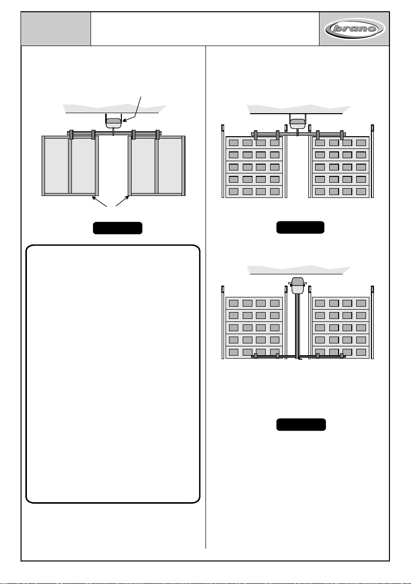
Two "One-piece" Tip-Up Doors Shown.
Two Sectional Doors With A Vertically
Mounted Motor between the doors.
( Similar to"side-mount" system
used for Steel Roll-Up Doors )
Single Door Operator Centrally Mounted
Between Two "One-Piece Tip-Up Doors
Which Are Rigidly Coupled Together.
Single Door Operator Centrally Mounted
Between Two Sectional Doors Which Are
Rigidly Coupled Together.
Unsafe Installation Practices
Do Not Install Door Operators In This Way
SABS - IEC 60335-Part 2 - 1995 sets down
certainsafetystandardsfortheautomationof
garage doors. When two Tip-Up type doors
are coupled together in the way shown
above, the built-in "overload" sensors of the
door operator, regardless of make and type,
may be severly compromised to the extent
that they may not respond quickly enough, if
at all, to any obstructions in the path of the
door.
Should any door which is automated in this
manner cause an injury, or worse, to any
person or damage to property, both the
owner and the installer may be held jointly
and severably responsible and liable and
maysuffertheconsequencesthereof.
Homeowners are advised to reject such
installations lest they be incriminated in any
claims.
The installation of door operators in this
manner will render all warranties, wether
statedorimplied,nullandvoid!
Fig No. 10 Fig No. 11
Fig No. 12
page 05
“brano” door operator installation manual"
i n d u s t r i e s
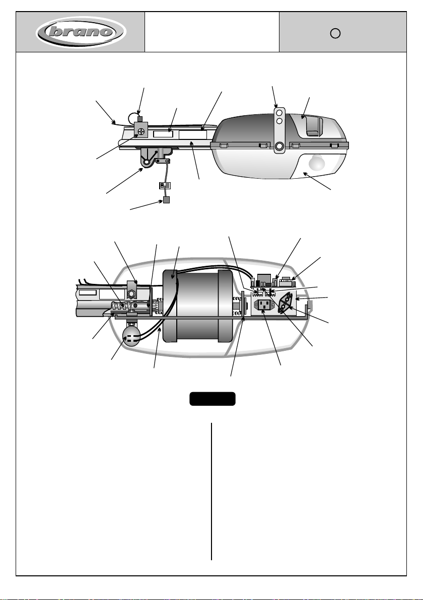
Electric
Motor
Motor
Capacitor
Rubber
Buffer
Base Plate
Lamp
Holder
"Opening" Sensor
Adjustor
"Closing" Sensor
Adjustor
Worm-shaft
Worm-shaft
Coupling
Wiring
Harness
Extrusion
Clamp P.C. Board
P.C. Tray
"Power ON"
Indicator Light
Power
Socket
Terminal
Connector
-pro alpha 2 0
00
LUBRICATION
DO NOT USE COMMON GREASE
USE ONLY "BRANO LUBRICANT GDO-L1" OR
"LOW-TEMP LUBRIPLATE" OR "AVGREASE28"
Serial Number
299 A 8 / 3478
Worm-shaft
Aluminium Housing
( Extrusion )
Emergency Pull
"Release Cord"
Light Diffuser
Lens Cover
Service
Cover
Lubrication
Label
Serial No.
Label
Traveller
Hanger
Bracket
"Open" Limit
Switch Wire
( Brown )
"Closed" Limit
Switch Wire
( Purple )
"Open"
Limit Switch
( "Closed" Limit
Switch not shown )
o
r
0
p
ha
p
al 2
0
-
0
LUBRICATION
DO NOT USE COMMON GREASE
USE ONLY "BRANO LUBRICANT GDO-L1" OR
"LOW-TEMP LUBRIPLATE" OR "AVGREASE28"
Serial Number
299 A 8 / 3478
GENERALDESCRIPTION
Electrically operated automatic garage door
operatorforuseondomestictypegaragedoors.
MAINFRAMEANDCOVERS
Galvanized steel frame supports the motor and
worm-screw housing. Moulded plastic cover
enclosesmotorandelectroniccontrolboard.
WORM-SCREWANDALUMINIUMHOUSING
Onepiecewormdirectlycoupledtothemotor.
O n e p i e c e a l u m i n i u m h o u s i n g .
ELECTRIC MOTOR
*Enclosed,fan-cooled,reversibletype.
*"SealedforLife"BallBearings.
*Singlephase-250W-50Hz-1450rpm-3,5A
POWERSUPPLY
*220V - singlephase - 50Hz
LIGHT
*Onelamp 100Wmaximumoutput.
*TypeBC-(Bayonetbase).
*Automaticcourtesylighttimer+/-3minutes.
*Light can be switched "ON" from the wall
pushbutton.
"pro-alpha 2000”
OPERATOR TERMINOLOGY
SECTION 2
Fig No. 13
brano industries (pty ) ltd
Copyright C
1998 / 1999 / 2001
page 06
“brano” door operator installation manual"
i n d u s t r i e s

3.6 Important Notes for Installers!
Always inspect the door first before
committingtoaninstallation!
Carefully inspect every component of the
garage door for signs of wear or damage. Be
particularlyvigilant formissingparts!
Checkfor .......
- stretchedorbrokenSprings,
- frayedorbrokenLiftingCables,(wireropes),
- wornrollers,pivotpinsandsheavewheels,
- damagedHinges,
- damaged Torsion Tubes and Support
Bearings,
- CableDrums,
- damagedLiftingandSteeringArms,
- damagedormissingStoppers,
- damagedormissinginternalLockingDevices,
- looseormissingnuts,boltsandscrews.
..... and repair or replace as necessary !
3.3 INSTALLATION PREPARATIONS
OnreceiptoftheDoorOperator,inspectthepackage
for any signs of shipping damage. If damage is
found, return the operator, complete with all
accessoriestoyoursupplier.
Insidethe package is a "packing slip". Stampedon
the slip will be a QC number, (Quality Control
number). Return this slip, or fax it directly to your
localagent withyourcomplaint.
BesuretoincludetheSerialnumberoftheoperator!
3.4 Check the contents of the package against the
"packing slip" to make sure it is complete. This
package contains all the hardware required to install
the operator onto a "standard" domestic garage
door. Also included are the Wall Push-button
Console, Kettle Plug Connector, "Safety" and
"Operation" information labels. If the door or the
garage itself does not conform to standard
specifications, special equipment may be required.
Contactyournearestagent/dealerforadvice.
The following items are not included in the
standardoperator hardwarekit:-
-a 3Pin-15Ampplugtop,
-lightbulb,(lamp)
-theelectricalpowersupplycable,
NOTE:-
"pro-alpha" Series 1 Door Operators
The installation techniques and especially the
electricalconnectionsandsetupproceduresfor
the Series 1 "pro-alpha" Door Operators is
different to those for the "pro-alpha 2000"
and“Aladdin”machines.
Refer to the specific instructions for the "pro-
alpha" Series 1 range of Door
Operators.
3.1 RECOMMENDED TOOLS
The tools required to successfully complete the
installationwilldependtosomeextentonthetypedoorto
be automated, i.e. is the door constructed of Steel,
Wood, Aluminium, Glass-fibre, or other material? The
more comprehensive the range of tools available, the
easier the job will be !!! Shown above is the range of
handtoolswerecommendyoushouldhave.
-Specialadaptororaccessorykits
-the Remote Controls. The remote controls
are not supplied as part of the basic operator kit
but are sold as optional extras as the type and
specificationsoftheremotecontrolswillvaryfrom
oneinstallationtoanother.
3.5 Ensure that you have the necessary tools to
complete the job. You are now ready to install the
dooroperator.
Turn to Sections 4& 5"Sectional" and "Tip-
UpDoorOperatorInstallationProcedures"
SECTION 3
PRE-INSTALLATION PREPARATIONS
Fig. 14
page 07
brano door operator installation manual"
i n d u s t r i e s

Low-Headroom Bracket for
Automatic Sectional Doors
1 KLHD - A
Description Product Code
SECTION 3
Locking Devices and Special Accessories
3.6.4 VeryImportant .............
If the door is balanced by means of
tension type springs, make sure the
Safety Cables are securely anchored.
If none are fitted to the door, insist that
these be fitted before the operator is
commissioned.
3.7 Locking Devices
It is necessary to render the locking devices
inoperative for normal automatic operation,
butdonotremovethementirely.
In the event of a malfunction of the door
operator, it is essential that the door may still
besecured.
The best way to do this is to pin the Lock
Cables or chains back with a screw or nail in
such a way that the Lock Catches are in the
"open"or"unlatched"position.
3.8 Garages Without Secondary Access
Doors
If there is no other means of access into the
garageexceptthroughthemaingaragedoors
themselves, it is necessary to install an
"Emergency Key-release" Kit for the door
operator.
It is also necessary to fit a normal outside "T"
Handle Lock to the door. In the event of a
malfunction of the operator system, the only
waytosecurethedoorwillbefromtheoutside
bymeansofthe"T"handleLock!
3.9 Special Accessories
Some doors may require the installation of
special equipment such as Low-Headroom
Bracketsinordertoallowthedoortowork.
Consult your “pro-alpha 2000"
dealerforadvice!
page 08
4 CABLE -SAFETY 1
"Spring Safety Cables" for
Tension Spring Systems.
1 KEYS
Emergency Key Release Kit
for Sectional and Tip-Up Doors
1 KEYPR
Emergency Key Release Kit
for Steel Roll-Up Doors
"Pro-Rola" System
Emergency Key Release Kit
for Steel Roll-Up Doors
"Side Mount" System
1 KEYR
“brano” door operator installation manual"
i n d u s t r i e s

ImportantNotes:-
The following table shows the minimum
amount of "Working Space" that is
required for the normal installation of
standard size Sectional doors. If the
space available is less than that stated
here, then special equipment may be
requiredtoundertaketheinstallation.
Certain assumptions have been made,
i.e.:-
1) Theopeningheightsare2135mmfor
standard doors or 2540 mm for
caravanheightdoors.
2) The structure is level, square, plumb
andtrueasthecasemaybe.
3) For Sectional Doors, the door panel
overlaps the opening by no more
than30mmatthetopandsides.
Contact your local dealer for advice
before committing yourself to a difficult
installation!
High-lighted Row Refers to a Standard Height 5 Section Door
( All dimensions in mm )
Floor
Level
Door Opening Height
Standard = 2135 mm
Back-reach of Door Operator
Hanger Bracket Position
Maximum Draw Length
Floor to
“Highrise" Level
Required
Headroom
Lintel
Ceiling
"High-Rise"
Point of Door
pro-alpha 2000
Path of Topmost
Section of the Door
12
3
Floor to top of
door operator
5
6
7
4
Opening No. of Track Headroom Highrise Hanger Top of Back-reach Draw
Height ( 1 ) Sections Radius Required ( 2 ) Level ( 3 ) Bracket ( 4 ) GDO ( 5 ) GDO ( 6 ) Length ( 7 )
2135 6 254 (10") 315 2380 2920 2445 3100 2350
2135 5 305 (12") 360 2420 2920 2500 3100 2350
2135 4 380 (15") 440 2500 2920 2575 3100 2350
2550 6 305 (12") 360 2840 3620 2910 3800 3160
2630 5 380 (15") 440 2925 3620 3070 3800 3160
Section 4
"Working Space" Tables for
Sectional Door Operators
All dimensions in mm
( Vertical scale is exaggerated)
Ceiling
0,0
40
80
120
160
200
240
280
320
360
400
0,0 100 200 300 400 500 700600 800 900 1000
..............
2200 2300 2400 2500
Lintel Level
Back-space
Recommended Headroom = 400 mm
Headroom
Minimum space required for
Door Operator Shaft = 75 mm.
page 09
Fig. 15
Fig. 16
4.1 Operator "Working Space”
“brano” door operator installation manual"
i n d u s t r i e s
Copyright C 1987 / 1990 / 1999 / 2001
brano industries (pty) ltd
20
60
100
140
180
220
260
300
340
380
0,0
400

Copyright C
1987 / 1990 / 1999 / 2001
SECTION 4
INSTALLATION PROCEDURES
SECTIONAL DOORS
4.2 Operator"WorkingSpace"
ApplicabletoAllSectional Doors!!!
Irrespective of the type or size of the
door that is to be automated, it is
absolutely essential to have adequate
"Working Space" for the equipment to
operatein.
The most important dimensions to
considerare:-
1) AvailableBackspace
2) AvailableHeadroom
3) Floor-to-"Highrise"point
4) Floor-to-TopofOperator
Inotherwords..........
.......theOperator"WorkingSpace"!!!
These 4 factors will determine the performance and
functionalityofthefinishedproduct!
Other useful information is included for installation
purposes. Refer to the relevant sections of this
manual.
Minimum Clearance Required
From Door "High-rise Point" to Ceiling.
75 mm
Sectional Doors
Operator- to-DoorClearanceat
"highrisepoint"approx.20mm
Fig. 17
Path of Topmost
Section of the Door
"High-Rise"
Point of Door
brano door operator installation manual"
page 10
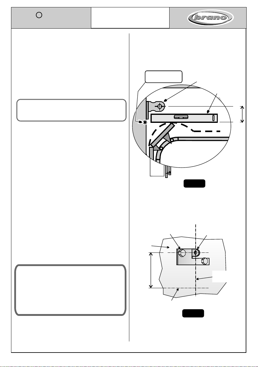
DoorTowingBracketandTopRoller
Bracketmustbeapproximately
inlinewitheachother.
Dimension "X"
*
Fig. 18
Wall Anchor
Bracket
Door Towing
Bracket Top Roller
Bracket
*
"X"
approx.
Centre Line of Door
4.3 Mounting the "Wall Header
Anchor Bracket"
Door
Track
View of Door From Inside
Header Bracket Position
Dimension “X”
( approximate value )
Track Horizontal Dimension
Radius Track “X" (approx)
Colour
250 mm Orange 300 mm
305 mm Green 360 mm
380 mm Blue 430 mm
i n d u s t r i e s
4.3.1 First ......Establish the centre-point of the
door.Mark-offthecentrepointalongthetop
rail.
4.3.2 Next..... Draw a vertical line on the wall
abovethedooratthecentre-pointposition.
4.3.3 Then..... Slowly raise the door taking note
of the highest position reached by the door
asitmovestothe"full-open"position.
Note:- Sectional Doors rise above
their "closed" positions as
theyopen.
4.3.4 Measure the height above the floor of the
"high-rise point" of the door. This
measurement is necessary in order to
establish the position of the Header
AnchorBracket.
4.3.5 Make a mark on the wall corresponding to
the "high-rise point" of the door. The
HeaderAnchorBracketisfixedabovethis
mark.
4.3.6 Position the Header Anchor Bracket, on
the wall in such a way that the right angle
face of the bracket coincides with the
centre-linemarkofthedoor.
4.3.7 Mark the positions for the fixing screws and
drill 10 mm dia. holes approximately 100 mm
deep. Insert the 2 "Green" plastic wall plugs
into the holes and fix the Header Anchor
Bracket in place using the two M 8 x 90 mm
Hex-head Washer-faced Lag Screws
supplied.
Note:-
It is very important that the Header
Anchor Bracket is well secured as
this fixture takes all the forces
actinginthesystem.
Fig. 19
Spirit Level
Wall Header
Anchor Bracket
"High-Rise"
Point of Door
Wall
M 8 x 90 Hex-Head
Coach Screws Wall Anchor
Bracket
Fig. 20
Centre Line
of Door
"High-rise"
Level of Door
80 - 130 mm
80 - 130 mm
door operator installation manual"
page 11
Copyright C 1987 / 1990 / 1999 / 2001
SECTION 4.3
Installation Procedures For
SECTIONAL DOORS
i n d u s t r i e s
Path of Topmost
Section of the Door
Ideal Clearance 20 - 50 mm
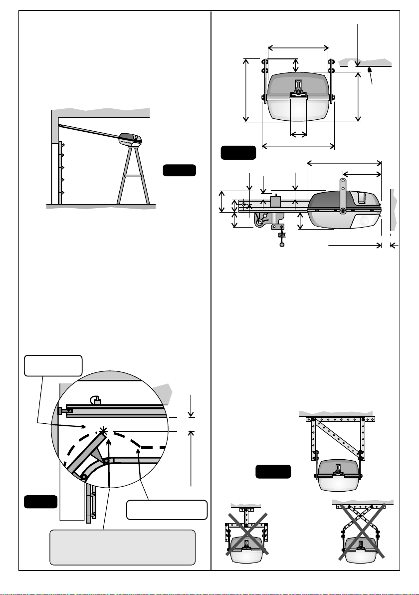
4.4 Mounting the "pro-alpha"
GarageDoor Operator.
4.4.1 For all overhead type garage doors, the
operatorissuspendedfrom the ceiling of the
garage by means of 2lengths of Punched
Angle which are attached to the Hanger
BracketsfixedtothePower-Head.
4.4.2 First..... Attach the Aluminium Extrusion
of the operator to the Header Anchor
Bracket using the M 8 x 25 Hex-head Set
Screwsupplied.
4.4.3 Next..... Temporarily support the Power-
head from the ceiling by means of a suitable
rope or prop it up with a ladder as shown in
Fig.21
4.4.4 Then..... Openthegaragedoorfully. This
willassist you to position the operator on the
"centreline"ofthedoor.
Preferred
Arrangement
Not
Recommended
4.5.1 MountingthePower-head
4.5.2 Establish the position of the nearest roof
beams or other suitable overhead structures
from which the operator may be supported.
Using the lengths of Punched Angle and
Fasteners supplied, suspend the operator
fromtheceiling.
4.5.3 Take care to ensure the operator is
positioned along the extended centreline of
thedoor.
Note:-
For all Overhead Track type doors, the
operator is mounted in such a way that it
is"horizontal",i.e."parallel"tothefloor.
Sectional Doors
Operator - to - Door Clearance
at "high-rise point" 20 - 50 mm
Fig. 21
Fig. 23
Fig. 22
Fig. 24
4.5 Useful Dimensions
370
10
60
93
67
58
46
190
Minimum
Back Clearance
20
35
230 Over-all
200
43
200
160
40
Ceiling
Minimum
Top Clearance
page 12
"High-Rise"
Point of Door
10 mm
Pro-alpha 2000

4.6 Restricted Headroom Installations
The Hanger Brackets are designed to be readily
adaptable for "low-headroom" installations. Make a 90
degree bend in the Hanger Bracket through the centre of
the lower of the two holes as shown. The bracket may
then be fastened directly to the ceiling. The clearance
between the ceiling and the operator will be sufficient to
allowtheremovaloftheoperator'sServiceCover.
Bend Line
09
Ceiling
minimum 10 mm
4.7 AttachingtheDoorBracket
- SectionaltypeDoors
4.7.1 TheDoorBracketisattachedtothedooratthe
centreline position in such a way that the
Clevis Pin in the Door Bracket is
approximately in line with the topmost
Rollersof thedoor.
4.7.2 Usethe threeNo 12 x 30 mm slotted pan-head
head screws provided to fix the Door Bracket
tothedoor.
4.8 AttachingtheTowingArms
OntoSectionalTypeDoors.
4.8.1 Use both the "L" Shaped Towing Arm and
theStraightTowing Armtocouplethedoorto
the traveller as shown in Fig 27. The "L" Arm
isattachedto thedoorwhilst theStraight Arm
isconnectedtotheTravellerasshown.
4.8.2 Use the two 10 mm dia. Clevis Pins and 2,5 mm
Split-Pins to couple the towing arm to the door
bracketandtraveller.
IMPORTANT NOTES:-
4.8.3 The towing arm should make an angle of
between75 and 80 degrees to the horizontal
whenthedoorisintheclosedposition.
4.8.4 The security of the locked door is a
function of the angle which the "Towing
Arm"makeswiththehorizontal.
15 degrees off the vertical is the optimum
angleforSectionaltypeDoors.
Door Towing Bracket Position
Roller Axis
Top Rail
of Door
Centre Line
of Door
Door Towing
Bracket
C/Line of
Clevis Pin
ptTo Sec ion
door
light
brano industries
CAUTION
Multi function
Push-button Console
and Label
Fig. 25
Fig. 27
Fig. 26
Approx.
15 Angle
75 - 80
Garage
Access
Door
page 13
Now turn to Section 6, page 18
forPCBoardconnections!
Brano door operator installation manual"

SECTION 5
"WORKING SPACE" REQUIRED
FOR TIP-UP DOOR OPERATORS
Tip-Up Doors
Op er ato r t o Do or
Clearance at "high-rise"
point 20-50mm
2575 mm - Standard height Tip-UP doors
Hanger Bracket Position
Fig. 29
i n d u s t r i e s
"brano door operator installation manual"
page 14
5.1 Operator"WorkingSpace"
ApplicabletoAllTip-Up Doors !!!
The same criteria as for Sectional doors apply
toTip-Uptypedoors.
See the diagram above and the relevant door
installation manuals for specific information
anddimensions.
Path of Top of Door
"HIGH-RISE"
Point of Door
150 mm
Minimum Clearance
Door's "Hig-hrise Point" to Ceiling
Floor
Level
Height of Door Opening
Standard = 2135 mm
Floor to "High-rise" Point
( +/- 2310 mm for std height door )
Top of Door, ( closed ).
Underside of Door Operator
Floor to Top of Wall Anchor Bracket.
Path of Top of Door
"High-Rise"
Point of Door Ceiling
"Highrise"
Level
Back-reach of Door Operator.
Minimum = 2760 mm for Std height door.
Available
Headroom
Lintel
2210 mm Maximum Draw Length
Max. distance Traveller can move.
Fig. 28
250 to 300 mm
Headroom Required for Tip-Up Doors
( All dimensions in mm. )
Steering Optimum Minimum
Arm Headroom Headroom
Setting Required Required
"Low" - 1 Not suitable for automation !
"Normal" - 2 300 200
"High" - 3 400 325
*Note:-If the Headroom Available is less than
theminimumrequired, specialequipment and
/ordoorsmayberequired.
Headroom
( See Table )
Required

NowturntoSection6,page18forPC
Boardconnections.
5.4.2 Use the two 10 mm dia. Clevis Pins and 2,5
mm dia. split-pins to couple the towing arm
tothedoorbracketandtravellerassembly.
5.4.3 IMPORTANT:- Theanglebetweenthe
Towing Arm and the horizontal plane
shouldbeasfollows:-
Tip-Up Doors - between 15 and 30
degreestothehorizontalwhenthedoorisin
theclosedposition.
5.4.1 AttachingtheTowingArm
Use the "Straight" Towing Arm, (Part
2TOWT),tocouplethedoortothetravelleras
showninFig.32.
If the "L" shaped towing arm is to be used,
(Part 2TOWLS ), use the arrangement
showninFig.33.
5.2 One-piece Trackless and Pivot Type Tip-
UpDoors
5.2.1 The Door Bracket is attached to the door at
the centre-line position as close to the top of
thedooraspossible.
5.2.2 Use the three # 12 x 28 mm hex head Lag
Screws provided to fix the Door Bracket to
thedoor.
5.5 Alternative Towing Arm
Arrangement for TIP-Up Door
Door Towing
Bracket
"L" Shaped Towing Arm Arrangement
Door Towing
Bracket
15 - 30
Straight Towing Arm Arrangement
SECTION 5
INSTALLATION PROCEDURES
TIP-UP DOORS
Position3
"High-headroom"Position
Best position for automatic
operation. Minimum Headroom
required=350mmabovedoor
Position1-"Low-Headroom"Position
Notsuitableforautomaticoperation.
Position2-"Normal"Position
Most commonly used position for
automatic operation. Minimum
Headroom required = 250 mm
abovedoor
Door Jamb
Mounting Channel
12 3
5.3 Steering Arm Settings
Jamb Mounted
"Power Plate"
Fig. 30
Fig. 31
Fig. 33
Fig. 32
VIEW OF INSIDE OF DOOR
Fix the Door Towing Bracket
ascloseto thetopof thedoor
aspossible.
Door Towing
Bracket
Door Jamb
Mounting Channel
*
Wall Anchor
Bracket
Centre Line
of Door
page 15
i n d u s t r i e s

5.6 Installation Of Door Operator On A Jamb-Spring
System Tip-Up Door Using An Extended Towing Arm
Path of Door Insufficient clearance available
between door and ceiling for an operator.
Installation In Garage With “Low
Headroom”
“TracklessTip-Up”DoorsOnly!!!
If there is insufficient clearance
between the path of the door and the
ceiling, it is permissible to move the
motor back away from the door and fix
the "Anchor Bracket", (or Header
Bracket),to the ceiling andmakeuse of
an "Extended Towing Arm" to couple
thedoortotheoperator.
*
po
r
0
0
a
-0
h
p
a
l2
SECTION 5
PROBLEM INSTALLATIONS
i n d u s t r i e s
Fig No. 34
" H i g h r i s e " P o i n t .
Nor mal P ath o f Doo r wit h
standard type “Adjustable Top Roller
Bracket" Installed Door Clearance Increased
by approximately 60 mm
Door in fully
"Opened Position"
"Highrise" Point.
Path of Door with
"Low-headroom"
Brackets Installed.
Door
Track
"Low-headroom" Bracket
Rollers
Automatic Door Installation
5.7 Installation Of Door Operator On A Sectional Door
Having Insufficient Headroom For A Door Operator
Fig No. 35
page 16
Fig No. 36

Ifyouexperiencea problem......... ChecktheInstallation!
Ifthatdoesn’thelp ......... ReadtheManual!
Iftheproblempersists ........ Book yourself into one of our
TrainingCourses!
Thereisnosubstitutefordoingitrightthefirsttime!
Fig No. 37
5.8 “Emergency Key-Release” Mechanism For Sectional and Tip-Up Doors
The "Emergency Key-Release" is a
specialmechanism whichisfittedtoa
doorwhen....
..... the only access into the garage
is through the garage doors
themselves, i.e. there is no back or
sidedoorentranceintothegarage.
This special release mechanism
permits the manual operation of the
door in the event of a power failure or
otherbreakdownofthesystem.
The Installation procedure for both
Sectional Doors ( shown ), and Tip-Up
Doorsisthesame.
PULL
STEEL CABLE
TRAVELLER LEVER
in "normal"
operating position
LOCK LOCK
CYLINDER
1/4 TURN
KEY
"pro-alpha 2000"
SECTION 5
PROBLEM INSTALLATIONS
i n d u s t r i e s
page 17

C
BEAM
11
LIGHT
BEAM
LOCK
TRIGGER
COMMON
COMMON
12 V +
Fig. 40
SECTION 6
"pro-alpha 2000"
PC Board Connections Rev 2 April 1999
Rev 3 October 2001
CONNECTING THE RADIO RECEIVER
Aerial - Do not cut
or remove
Dipswitch
Block
( Simple Dipswitch Type )
Radio Connections
to Door Operator's
PC Control Board
Operator PC Board
Typical Radio
Receiver Board
Terminal
Block
( Red )
( Green )
( Black )
( Blue )
1
2 3 4 5 6 7 8 9 10 1 12
1
ON
OFF
--
COMM
++
12 V
NO
NC
NON-LATCH
LATCH
GND
A
brano
Note:-
PC Board jumper switch is
set to "NORMAL" position.
Connect the Radio
Receiverasshown.
TakeNote:-
1) If no "Safety Beams"
are to be fitted then the PC
Board "jumper switch"
must be set to the
"Normal"position.
2) The wire colours as
supplied may vary from
thoseshown.
Fig. 38
"DOWN Over-load"
Sensor Adjustment.
( Sensitivity )
"UP Over-load"
Sensor Adjustment.
( Sensitivity )
Terminal Block for
connection of Radio Receiver,
Wall-Pushbutton and
Safety Beams.
"pro-alpha 2000" PC BOARD - GENERAL LAY-OUT
brano industries (pty) ltd.
PC Board Lay-out
FORCE ADJUSTMENT
CLOSING OPENING
DOWN
UP
LED
+
OVERL.
UP
DOWN
LAMP
220 V
COMMON
NORMAL
C
BEAM
LIGHT
BEAM
LOCK
TRIGGER
COMMON
COMMON
12 V +
11
NORMAL
Fig. 39
CONNECTING THE WALL PUSH-BUTTON
Lock
( White )
( Brown )
( Blue )
( Black ) Light
Trigger
Common
Door
Push-Button
Light
Push-Button
Operator PC Board
pro-alpha
door
light
lock
off on
brano industries
Wall Mounted
Push-button Console
C o n n e c t t h e W a l l -
Pushbuttonasshown.
TakeNote:-
1) If no "Safety Beams"
are to be fitted then the PC
Board "jumper switch" must
be set to the "Normal"
position.
2) The wire colours shown,
( White, Brown, etc. ), are
typical only. The colours of
the wires as supplied may
varyfromthoseshown.
Note:-
PC Board jumper switch is
set to "NORMAL" position.
C
11
LIGHT
BEAM
LOCK
TRIGGER
COMMON
COMMON
12 V +
BEAM
NORMAL
i n d u s t r i e s
"brano door operator installation manual"
page 18
Door Lock
Table of contents
Other Brano Industries Garage Door Opener manuals

Popular Garage Door Opener manuals by other brands

Garaga
Garaga SECURITY+ 3265GCM 1HP owner's manual

Chamberlain
Chamberlain Whisper Drive SECURITY+ WD822K Series owner's manual

Chamberlain
Chamberlain T owner's manual

Schellenberg
Schellenberg STA Slide 400 instructions

Chamberlain
Chamberlain Merlin Professional MT230 Installation and operating instructions

Abloy
Abloy DA460 Installation and commissioning manual


BFT
BFT KR92522800003 Installation and user manual

Raynor
Raynor 3245RGD 1/3 HP owner's manual

Whisper Drive
Whisper Drive 248739 owner's manual

Chamberlain
Chamberlain ATS 211 owner's manual

Chamberlain
Chamberlain C450 owner's guide

Comunello Automation
Comunello Automation RAMPART 600 Installation and user manual