Branson 3015r User manual

PREFACE
This manual is to provide servicing personnel with extensive information on the structure, service procedure,
removal and installation procedure, disassembly, troubleshooting and more for the 3015R(h)/3515R(h)/
4015R(h) and F36R(h)/F42R(h) tractor with high-end technology to ensure precise and rapid service.
Most accidents are resulted from negligence in safety precautions and directions, so it is very necessary to
follow such precautions and directions to avoid any safety accident beforehand. Service technicians should
provide quality service to prevent any safety accident and enhance customer satisfaction so they should fully
understand the service procedure, methods, inspection points and safety precautions for accurate service.
To ensure optimum condition of your tractor, it is highly recommended to use only BRANSON genuine parts
which are manufactured under strict quality assurance policy for premium quality, durability and reliability.
BRANSON is always committed to provide best quality products through extensive research, study and
development.
Information in this manual is subject to change without notice for improvement of the product.
Please keep this manual in a safe place. If there is any typo, incorrect information or question about this
manual, feel free to contact BRANSON.
(Jan, 2016)
BRANSON TRACTORS Co. Ltd.
※Remark
This manual does not contain all accidents and preventive measures that can occur during ser-
vice. Make sure to have this tractor serviced only by professional technicians with care.
Useonlygenuineparts,includingengineoilandtransmissionuid,speciedinthismanual.Oth-
erwise, it can affect the tractor's performance seriously.
NeverattempttoduplicatecontentsandguresinthismanualwithoutpriorapprovalbyBRANSON.

Precautions and instructions described in this manual and safety decals, such as DANGER, WARNING and
CAUTION decals, are important for your and machine's safety. If these instructions are not followed, you and
the vehicle can be severely injured and damaged. Read such precautions and instructions carefully for your
safety.
If any DANGER, WARNING or CAUTION decal is damaged or missing, order it from your dealer and have it
attached to the original position.
Important safety instructions are described with various symbols throughout this manual. Make sure to follow
such instructions. Their design and meanings are as follows:
MEANINGS OF SAFETY SYMBOLS
This symbol indicates potentially hazardous situation which, if not observed, may
result in death or moderate injury.
DANGER
This symbol indicates the most serious hazardous situation which, if not observed,
may result in death or serious injury.
This symbol indicates potentially hazardous situation which, if not observed, may result in
minor or moderate injury. Also, this can be used as a warning for an unstable action.
This symbol indicates important procedures or information to perform work with
more ease and skills.
Notes This symbol indicates information useful to users.
WARNING
CAUTION
IMPORTANT

HOW TO USE THIS MANUAL
1. Target readers
This manual is intended for technicians with mid to high level of service knowledge and skills for BRANSON
tractors. Make sure to understand this manual fully for rapid and accurate inspection and service.
2. Order of contents
This manual is a single book for the 3015R(h)/3515R(h)/4015R(h) and F36R(h)/F42R(h) tractor and contains
several useful chapters such as General Information, Engine, Clutch, Transmission, Front Axle, Hydraulic
System, Electric System. Information and diagrams in this manual are described based on the standard model
so they may be different from your vehicle due to different specifications by models. However, the same
instructions should be followed for service.
3. Body structure of this manual
This manual is structured as follows:
< Lower section >
< Upper section >
CHAPTER 3 CLUTCH3015R(h)/3515R(h)/4015R(h)/F36R(h)/F42R(h) TRACTOR
3. DISASSEMBLY
3.1 CLUTCH HOUSING REMOVAL
1. Park the tractor on level ground and apply the hand
brake.
2. Disconnect the negative battery cable.
3. Drain the transmission fluid.
4. Remove the hood and propeller shaft.
5. Disconnect the hydraulic hose, wiring connector
and various cables between the vehicle body
and engine.
6. Place a stand under the clutch housing and a
portable jack under the engine oil pan.
3.2 CLUTCH DISASSEMBLY
K20W303A
3-8
42hW-201601
8. Unscrew the mounting bolt (1) from the cutch
housing and engine mounting flange. Then, push
the front axle section to separate it from the
clutch housing.
9. For more detailed disassembly procedures, refer
to the instructions for engine removal in Chapter 2.
ITEM TORQUE VALUE
M14 nut (10.9T) 16.5 kg.m (119.34 lbf.ft)
M14 bolt (10.9T) 16.5 kg.m (119.34 lbf.ft)
2. Remove the clutch disc.
K20W304A
1
2
3
45

HOW TO USE THIS MANUAL
① Chapter
This indicates the current chapter.
② Body
Generally,guresanddiagramsareplacedintheuppersectionofapagewhileinformationanddescription
are set in the lower section. However, a large table or diagram may take a whole page. Each gure is
assignedwithagurenumberandalargeguremaybesetinaA3-sizepagelikeacircuitdiagram.
③ Model name
This indicates the corresponding model.
④ Publication classification
This indicates the publication category and date of this manual.
⑤ Page number
Each page is given with the corresponding number:
Example: 3-8
4. Other information
Thecomponentnamesusedinthismanualaresettoreecttheirfunctionssotheymaynotbeconsistentwith
the ones in other materials, such as the part list and user's manual, labels and decals.
Also,astheguresanddiagrams inthismanualarebasedontheproductatthetimeofitspublication,so
theymaydifferfromyouractualproduct.Thespecicationandotherinformationinthismanualaresubjectto
change without notice for design change or improvement of the product.

TABLE OF CONTENTS
◆ ELECTRIC SYSTEM ......................................................................................
◆ HYDRAULIC SYSTEM ..................................................................................
◆FRONT AXLE ................................................................................................
◆TRANSMISSION ............................................................................................
◆CLUTCH [MEC. MODEL] ..............................................................................
◆ENGINE .........................................................................................................
◆GENERAL INFORMATION ............................................................................
1
2
3
4
5
6
7
◆INDEX ...........................................................................................................
8


CHAPTER 1 GENERAL INFORMATION
TABLE OF CONTENTS
1.
GENERAL INFORMATION FOR SERVICE
..1-2
1.1 For safe operation.................................. 1-2
1.1.1 Work place...................................... 1-2
1.1.2 Working clothes and
other safety gears........................... 1-3
1.1.3 Tool ................................................. 1-3
1.1.4 Standard parts, lubricant,
grease and oil ................................. 1-4
1.1.5 Finishing up and checking.............. 1-4
1.1.6 Torque part ..................................... 1-4
1.1.7 Electric system ............................... 1-4
1.1.8 Safety during service...................... 1-5
1.1.9 Waste disposal ............................... 1-6
2. LOCATION OF DECALS..........................1-7
3. GENERAL INFORMATION FOR
MAINTENANCE .....................................1-11
3.1 Tightening torque..................................1-11
3.1.1 Hex. bolt.........................................1-11
3.1.2 Stud bolt ........................................ 1-11
3.2 Oil, grease, fuel and coolant
specications ....................................... 1-12
3.3 Electric device service......................... 1-12
3.4 Using standard part and adhesive....... 1-13
4. INSPECTION AND
CORRESPONDING ACTION.................1-15
4.1 Daily inspection ................................... 1-15
4.1.1 Checking work place .....................1-15
4.1.2 Checking condition around tractor...1-15
4.1.3 Checking when seating
on driver's seat ..............................1-15
4.1.4 Checking when turning
ignition switch ................................1-15
4.1.5 Checking when starting engine .....1-15
5.
GENERAL INFORMATION FOR SERVICE
...1-16
5.1. Machine history and information ......... 1-16
5.1.1 Serial number ................................1-16
5.1.2 Transmission serial number...........1-16
5.1.3 Engine number ..............................1-16
5.1.4 Hourmeter......................................1-16
6. COMPONENTS OF TRACTOR ..............1-17
6.1 Front and rear exterior view ................ 1-17
6.2 Interior view ......................................... 1-18
7. TRACTOR SPECIFICATIONS ............... 1-20
7.1 Exterior dimensions............................. 1-20
7.2 Majorspecications............................. 1-21
7.3 Driving speed....................................... 1-23
8. PERIODIC INSPECTION ....................... 1-24
8.1 Periodic maintenance schedule table.. 1-24
8.2 Inspection Description ......................... 1-26
8.2.1 Fueling into fuel tank..................... 1-26
8.2.2 Checking engine oil ..................... 1-27
8.2.3 Checking coolant amount ............ 1-27
8.2.4 Checking lamps ............................ 1-28
8.2.5 Checking seat belt ........................ 1-28
8.2.6 Cleaning radiator dust grill............ 1-28
8.2.7
Checking instrument cluster signals ....... 1-28
8.2.8 Changing engine oil...................... 1-29
8.2.9 Replacingengineoillter ............ 1-30
8.2.10
ReplacingHSTlter[HSTMODEL]
.. 1-30
8.2.11
Replacingtransmission/hydrauliclter
..1-31
8.2.12 Changing transmission
uid/hydraulicoil ............................1-31
8.2.13
Adjustingclutchpedal[MEC.MODEL] ..
1-32
8.2.14 Adjusting brake pedal .................. 1-33
8.2.15 Adjusting fan belt tension ............ 1-33
8.2.16 Checking fuel line ........................ 1-34
8.2.17 Cleaning air cleaner element....... 1-34
8.2.18 Battery ......................................... 1-35
8.2.19
Checking radiator and intake hoses ....
1-35
8.2.20 Applying grease........................... 1-36
8.2.21 Adding anti-freeze ....................... 1-37
8.2.22 Fuse and relay ............................ 1-38
8.2.23Tireinationpressure.................. 1-39
8.2.24 Checking toe-in ........................... 1-39
8.2.25 Adjusting front wheel toe-in......... 1-39
8.2.26 Tightening wheel bolt .................. 1-40

42hW-201601
1-2
CHAPTER 1 GENERAL INFORMATION 3015R(h)/3515R(h)/4015R(h)/F36R(h)/F42R(h) TRACTOR
1. GENERAL INFORMATION FOR SERVICE
1.1 FOR SAFE OPERATION
1.1.1 WORK PLACE
6015W101A
CAUTION
CAUTION
6015W102A
CAUTION
When working in or under the machine, make sure
to have a protected lighting equipment.
6015W103A
CAUTION
Haveareextinguisherinyourworkplace.
DANGER
-

42hW-201601 1-3
CHAPTER 1 GENERAL INFORMATION
3015R(h)/3515R(h)/4015R(h)/F36R(h)/F42R(h) TRACTOR
1
WARNING
Use the specif ied too ls for disas sembly and
assembly.
[If hh huuff
, it can lead to an injury or
damage to equipments and parts.
1.1.3 TOOL
1.1.2 WORKING CLOTHES AND OTHER
6015W105A
6015W106A
CAUTION
DANGER
6015W104A
Never work on the tractor only with a wood support
or other type of block or jack.
Do not use any lift or crane with insufficient rated
load capacity.
Make sure to wear working clothes, safety hat,
safety gloves, safety goggles and other safety gears
for your safety.

42hW-201601
1-4
CHAPTER 1 GENERAL INFORMATION 3015R(h)/3515R(h)/4015R(h)/F36R(h)/F42R(h) TRACTOR
1.1.6 TORQUE PART
lb
6015W109A
WARNING
WARNING
-
-
6015W110A
GREASE AND OIL
6015W107A
CAUTION
CAUTION
-
-
1.1.5 FINISHING UP AND CHECKING
6015W108A
Inspection
list

42hW-201601 1-5
CHAPTER 1 GENERAL INFORMATION3015R(h)/3515R(h)/4015R(h)/F36R(h)/F42R(h) TRACTOR
1
DANGER
K20W151A
WARNING
-
K20W150A
DANGER
-
-
K20W153A
K20W152A
CAUTION
-

42hW-201601
1-6
CHAPTER 1 GENERAL INFORMATION 3015R(h)/3515R(h)/4015R(h)/F36R(h)/F42R(h) TRACTOR
1.1.9 WASTE DISPOSAL
K20W156A
WARNING
-
-
-
-
-
K20W155A
DANGER
CAUTION
-
-
K20W154A

42hW-201601 1-7
CHAPTER 1 GENERAL INFORMATION3015R(h)/3515R(h)/4015R(h)/F36R(h)/F42R(h) TRACTOR
1
14, 15, 16
12, 13
10, 11
1, 2, 3 4, 5, 6 7, 8
9
To ensure safe work, check the location of the safety decals and always keep the safety precautions.
Keep the safety decals intact. If any decals is damaged or missing, attach a new decal.
2. LOCATION OF DECALS
F42W105A

42hW-201601
1-8
CHAPTER 1 GENERAL INFORMATION 3015R(h)/3515R(h)/4015R(h)/F36R(h)/F42R(h) TRACTOR
(4)No.:TA00040603A[MEC.MODEL]
(1) No.: TA00036924A
(5) No.: TZE4190000C4
(6) No.: TZE5110000B4
(2) No.: TZE5130000C4
WARNING
HOT
SURFACE
75IH=CB
Clutch pedal
Stopper
Locker
For the long storage, please
lock clutch pedal in the both
Traction and PTO clutch are
disengaged position
TA00040603A
75IH=CB
DIESEL ONLY
TZE4190000C4
Start only from
seat in park or
neutral.
Starting in gear
kits.
DANGER
TZE5110000B4
75IH=CB
TZE5130000C4
(3) No.: TZE5180000C4
K5FB=B;
(7) No.: TZE5160000B3
TO AVOID PERSONAL INJURY:
1. Read and understand the operator’s manual before operation
2. Before starting the engine, make sure that everyone is at a safe distance from the
tractor and that the PTO is OFF
3. Do not allow passengers on the tractor at any time.
4. Before allowing ohterpeople to use the tractor, have them read the operator’s manual.
5. Check the tightness of all nuts and bolts regularly.
6. Keep all shields in place and stay away from all moving parts.
7. Lock the two brake pedals together before driving on the road.
8. Slow down for turns, or rough roads, or when applying individual brakes.
9. On public roads use SMV emblem and hazard lights, if required by local traffic and
safety regulations.
10. Pull only from the drawbar.
11. Before dismounting lower the implement, set the parking brake, stop the engine and
remove the key.
TZE560000B3
75IH=CB

42hW-201601 1-9
CHAPTER 1 GENERAL INFORMATION3015R(h)/3515R(h)/4015R(h)/F36R(h)/F42R(h) TRACTOR
1
(10) No.: TZE5120000B4
TO AVOID PERSONAL INJURY:
WARNING
1. Attach pulled or towed loads to
the drawbar only.
2. Use the 3-point hitch only with
equipment designed for 3-point
hitch usage.
TZE5120000B4
(9) No.: TZE5140000B3
BEFORE DISMOUNTING TRACTOR:
1. PARK ON LEVEL GROUND WHENEVER POSSIBLE.
If parking on a gradient. position tractor at right angles
to the slope.
2. ALWAYS SET PARKING BRAKE.
Leaving transmission in gear with the engine stopped will
not prevent tractor from rolling.
3. LOWER ALL IMPLEMENTS TO THE GROUND.
Failure to comply to this warning may allow the wheels to
slip. and could cause injury or death.
4. LOCK SHUTTLE SHIFT LEVER IN NEUTRAL
POSITION AND STOP THE ENGINE.
TZE5140000B3
WARNING
(8) No.: TZE5170000B3
TO AVOID PERSONAL INJURY OR DEATH FROM ROLL-OVER;
TZE5170000B3
1. BRANSON recommends the use of a Roll-Over Protective
Structures(ROPS) and seat belt in almost all applications
2. Remove the ROPS only when it substantially interferes with
operation or itself presents a safety risk. (Examples include work
in orchards and vineyards.) ALWAYS REINSTALL IT BEFORE
USING THE TRACTOR IN OTHER APPLICATIONS.
3. Never use just the seat belt or just the ROPS. They must be
used together. For further details, consult your Operator’s Manual
or your local dealer.
ZDUQLQJ
(11) No.: TA00015596B
WARNING
TO AVOID PERSONAL INJURY:
1. Keep PTO shield in place at all times.
2. Do not operate the PTO at speeds faster
than the speed recommended by the
implement manufacturer
3. For towing PTO-driven implements set
drawbar at towing position.
(see operator’s manual)
4. Keep hands, feet and clothing away.
TA00015596B

42hW-201601
1-10
CHAPTER 1 GENERAL INFORMATION 3015R(h)/3515R(h)/4015R(h)/F36R(h)/F42R(h) TRACTOR
(15) No.: NTE5210000C4
K5FB=B;
NTE5210000C4
DEATH OR INJURY MAY
RESULT IF THE TRACTOR
ROLLS OVER WITH THE
ROPS IN THE FOLDED
DOWN POSITION.
OPERATE THIS TRACTOR
WITH THE ROPS FOLDED
DOWN ONLY WHEN
NECESSARY.
(16) No.: NTE5220000C4
This structure’s
protective capability
may be impaired
by structural
damage, overturn,
or alteration.
If any of these
conditions occur,
the structure
must be replaced.
NTE5220000C4
K5FB=B;
(14) No.: NTE5150000C4
K5FB=B;
Use seat belt
NTE5150000C4
(12)No.:TZE4100000B4[MEC.MODEL]
WARNING
CONNECT THE LEFT
BRAKE WITH RIGHT
BRAKE WHILE ON THE
ROAD
DISCONNECT CONNECT
CONNECT ROD
TZE4100000B4
(13) No.: TZE5770000B3
75IH=CB
TO AVOID PERSONAL INJURY(OPERATING ON SLOPES)
1. If descending a slope, never disengage the clutch or shift levers
to neutral.
Doing so could cause the tractor to speed up out of control.
2. Slow down for slopes, especially when transporting heavy,
rear mounted equipment.
3. Before descending a slope, shift to a gear low enough to
control speed without using brakes.
TZE5770000B3

42hW-201601 1-11
CHAPTER 1 GENERAL INFORMATION3015R(h)/3515R(h)/4015R(h)/F36R(h)/F42R(h) TRACTOR
1
3. GENERAL INFORMATION FOR MAINTENANCE
3.1 TIGHTENING TORQUE
3.1.1 HEX. BOLT
ITEM
BASE TOLERANCE
N.m kgf.m lbf.ft N.m kgf.m lbf.ft
M8 11.8 ~ 15.6 1.2 ~ 1.6 8.68 ~ 11.5 8.82 ~ 11.8 0.90 ~ 1.2 6.51 ~ 8.67
M10 24.6 ~ 31.3 2.5 ~ 3.2 18.1 ~ 23.1 19.7 ~ 25.4 2.0 ~ 2.6 14.5 ~ 18.8
M12 29.5 ~ 49.0 3.0 ~ 5.0 21.7 ~ 36.1 31.4 3.2 23.1
3.1.2 STUD BOLT
ITEM NO GRADE OR 4 T 7T 9 T 8.8 T 10.9 T 12.9 T
M6
8.8
(0.9)
[6.4]
11
(1.1)
[8.1]
-
9
(0.9)
[5]
13
(1.3)
[10]
14
(1.4)
[9]
M8
20
(2.0)
[14.7]
25
(2.6)
[18.4]
14
(1.4)
[10.3]
23
(2.3)
[17]
33
(3.3)
[25]
40
(2.9)
[29]
M10
42
(4.3)
[30.9]
52
(5.3)
[38.3]
28
(2.9)
[20.6]
45
(4.5)
[33]
65
(6.5)
[50]
70
(7.0)
[50]
M12
68
(6.9)
[50.1]
84
(8.6)
[61.9]
44
(4.5)
[32.4]
80
(8.0)
[60]
115
(11.5)
[85]
125
(12.5)
[95]
M14
120
(12)
[88.5]
140
(14)
[103.2]
-
125
(12.5)
[90]
180
(18.0)
[133]
195
(19.5)
[145]
M16
180
(18)
[132.2]
220
(22)
[162.2]
-
195
(19.5)
[140]
280
(28.0)
[200]
290
(29.0)
[210]
M18
260
(27)
[191.7]
290
(30)
[213.9]
-
280
(28.0)
[200]
390
(39.0)
[285]
400
(40.0)
[290]
M20
360
(27)
[265.5]
400
(41)
[295.0]
-
400
(40.0)
[290]
550
(55.0)
[400]
-
Unit:N.m(kgf.m)[lbf.ft]

42hW-201601
1-12
CHAPTER 1 GENERAL INFORMATION 3015R(h)/3515R(h)/4015R(h)/F36R(h)/F42R(h) TRACTOR
ITEM
SPECIFICATION REMARKS
MEC. MODEL HST MODEL
Fuel 27ℓ(7.13u.s.gal) Diesel fuel (KS 2) Summer: S, Winter: W
Engine oil 4.3ℓ(1.14u.s.gal) SAE15W-40
3015R(h)/3515R(h)/4015R(h) (Final Final Tier4):
Grade CJ or higher
F36R(h)/F42R(h) (StageⅢA):
Grade CG or higher
Grease Small amount High load No. 2 of
KSM 2130 Multi-purpose
Coolant Radiator:5.0ℓ(1.32u.s.gal)
Reservoirtank:0.45ℓ(0.12u.s.gal)
BRANSON genu-
ine anti-freeze No. 2 of KSM 2142, permanent use
Transmissionuid
and steering oil
34ℓ(8.98u.s.gal) 37ℓ(9.77u.s.gal) TF500 Texaco TDH oil, 1893
Chevrontractorhydraulicuid
Front
axle oil 6.4ℓ(1.69u.s.gal) SAE#90 Gear oil
※If the ambient temperature is below 50°F (10°C), use diesel fuel for winter season.
3.3 ELECTRIC DEVICE SERVICE
1. When disassembling or repairing any part
applied with voltage, disconnect the negative
batterycablerst.
2. W he n d i sc o nn ec t in g t h e b at t e r y c a b le s,
disconnect the negative c able f irst. When
connectingthem,connectthepositivecablerst.
3. Apply grease to the battery terminals and cover
them securely after connecting the batter y
cables.
4. When charging the battery, it produces hydrogen
gas and chlorine. Therefore, disconnect the
battery and move it to an isolated well-ventilated
area with no f lammables and flame before
charging.
6015W165A

42hW-201601 1-13
CHAPTER 1 GENERAL INFORMATION3015R(h)/3515R(h)/4015R(h)/F36R(h)/F42R(h) TRACTOR
1
3.4 USING STANDARD PART AND ADHESIVE
When replacing a worn or damaged part, use a
new part that meets the international standard.
When replacing a packing or O-ring, fit a new
one. Before installation, apply grease to the
O-ring or oil seal ring.
When assembling a snap ring on a shaft or in a
hole, ensure its sharply angled side to point the
directionofforceasshownintherstgure.
When installing a spring pin, inser t its split
portion in the direction to be forced as described
inthesecondgureabove.
1.
2.
3.
4.
When the oil grooves are engaged with the
thrust washer, be careful with assembly.
6.
6015W114A
Replace the split pin with a new one and fix it
rmly.
5.
6015W115A
6015W116A
Oil groove
6015W113A
Snap ring for shaft Snap ring for hole
Section applied
with force

42hW-201601
1-14
CHAPTER 1 GENERAL INFORMATION 3015R(h)/3515R(h)/4015R(h)/F36R(h)/F42R(h) TRACTOR
Use a liquid sealant removal scraper (flat) to
remove any sealant left on the case. Make sure
not to make any scratch bigger than 0.3 mm
(0.012 in). If the surface is scratched, grind it with
an oil grinder.
7.
6015W117A
Scraper
CAUTION
-
6015W118A
Liquidseal-
ant
Cut second step
Mating surface
3 - 3.5 mm
CAUTION
-
-
6015W119A
Apply
Tool
3 - 3.5 mm
Liquidsealant
This manual suits for next models
9
Table of contents
Other Branson Tractor manuals

Branson
Branson 8050 User manual

Branson
Branson 00 Series User manual

Branson
Branson 9550C User manual

Branson
Branson 25 series User manual
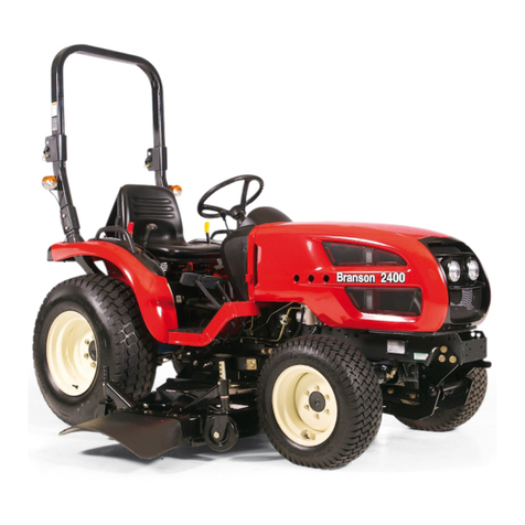
Branson
Branson 2000 series User manual
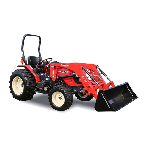
Branson
Branson 20R series User manual
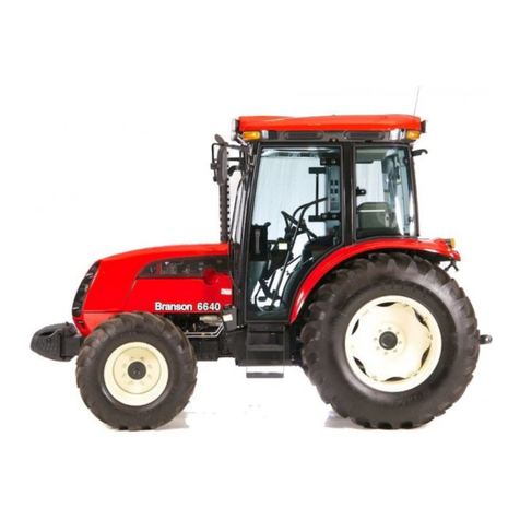
Branson
Branson 6640C User manual
Branson
Branson F36r User manual
Branson
Branson 00 Series User manual

Branson
Branson 00 Series User manual


