Allis-Chalmers HD 6B User manual

Topic Title
Page
Air Pre-Cleaner
and
Air
Cleaner
..........
42
Avoid Unnecessary Engine Idling
..........
17
Cold
Weather
Engine Primer
..............
44
Cold
Weather
Operation
.................
19
Driving Instructions . . . . . . . . . . . . . . . . . . . . .
17
Electrical System
·.
. . . . . . . . . . . . . . . . . . . . . . 40
Engine Clutch
and
Clutch Brake . . . . . . . . . . . .
51
Engine Control Adjustments . . . . . . . . . . . . . . . 49
Engine Cooling System
.'
. . . . . . . . . . . . . . . . .
20
Engine Lubrication Syste.m·
.......•.......
36
Fuel
Storage
..........
,
.............
·.
. 9
I •
Fuel System~
...............
~
. . . . . . . . . . . 22
General
Description . . . . . . . . . . . . . . . . . . . . 4
General
Specifications . . . . . . . . . . . . . . . . . . 5
-Governor
......................
:..
. . . . . 34
Operating
C~~trols
and
Instruments .
-~
. . . . . . 13
Operating
in
Mud
or
Water
; . . . . . . . . . . . . . 19
Periodic Adjustment . . . . . . . . . . . . . . . . . . . . .
11
Periodic Lubrication·
and
Preventive
Maintenance
........................
10
Topic .
Tit.le
Periodic Service
.......................
.
Preparation
of
Tractor for
Storage
.......
\ .·
Preparation of Tractor for
Use
..........
: .
Routine Service
.......................•
10-Hour Service
...................
.
100.Hour
Service
...................
.
200-Hour Service
...................
.
400-Hour Service
1000-Hour Service
...................
.
Speciflcaflons of
Fu.el
....................
.
Specifl~ations of Lubricants
..............
.
StartintJ
and
Stopping of Engine
..........
.
Steering Brakes
.....
,.
.................
.
Steering Clutches
......................
.
T.-ack
and
Traek: l~ler Adjustment
...........
:
Tractor
and
Engine Serial Numper
.......
··
Valve Adjustment
and
Cylinder
Head
...
el(··
••

The/,Model
"HD
68"
Tractor
is
a 12,400 pound track·type tractor
p~,'l,(ered
with a
:f'~ylinder, 4 cycle
"DIESEL"
engine.
Power from the engine
is
transmitted' through a single plate, over-,center
type
,engine
clutch to the transmission through q universal ;oint drive shaft assembly.
From
the trans·
mission the power
is
transmitted
to
the bevel gear
and
from fhe bevel gear through the ·
steering clutches to the final drives
and
the track
driv!,!
·sprockefs.
The
transmission provides 5 forward speeds ranging
from
1.5
M.P.H.
in
low
gear
to
5.5
M.P.H.
in
high gear
and
a reverse
speed
of
2.0 M.P.H., under full governed e,n9ine
speed
of
i800
R.P.M.
·
Mechanical self.energizing brakes, wide operator's seat,
and
uno8structed view
of
the
front
of
both
tracks assure ea$y, positive
contro.l
of
the tractor
at
all times.
The
standard model tractor
is
equipped
with 24-volt electric starting
and
light equipment,
suction
type
cooling
fan,
muffler, full width crankcase guard, bumper, hinged.radiator
guard,
and
13° grouser track shpes. The truck wheels, track idlers,
and
track support
rollers have positive type seals.
TRACK
RHEASE
YOKli
AIR
PRE-CLEANER
TRUCK
WHEEL
OUTER
GUARD.
(SPECIAL·
EQUIPMENT)
TRUCK
WHEEL
INNER
GUARD
(SPECIAL
EQUIPMENT)
c.1------------------------ Model
HD
68 Tractor
-----------------
FIG.
1

~'GcEJ~
ER
A L/ ·SP
E,C:l
fI G.~,T
l;,G>;N'Sir
.
(STANDARD
TRACTOR)
General
Dimensions
and
Weight:
Overall Length
...
,
..........•.
x
.•.....
10ft.
73<6
in.
Overall Height (to
top
of exhaust stgck)
....
5 ft.
8%
in.
Overall Width (standard shoes)
..........
,6
ft.
63.4
in.
Ground Clearance
........................
111,4
in.
Drawbar Height (c:enter fine of jaw)
......
,
..
131
~6
in.
Lateral Drawbar Movement
.....•............
21
in.
Shipping Weight (approximate)
...
·
.......
12,400 lbs.
Tracks:
Width of
Standard
Track Shoes
...............
13 in.
Maximum Width Track Shoes Available
.........
20
jn.
Tread
Wid.th
(center-to-center)
.................
60
in.
Engine:
Make·
......................
"Allis-Chalmers" Diesel
Model
..................................
HD-344
Type
............................
.4
Strol<e
Cycle
(Naturally Aspirated)
Number of Cylinders
............................
4
Bore
.........•............................
4K6
in.
Stroke
........
·
............................
5'<6
in.
·Crankshaft Rotation (when viewed
from fan end)
........................
Clockwise
Number of Main Bearings
...
,
..............
·
.....
5
Piston Displacement
....................
344 cu. in.
L"ubrication
...........................•..
··•.
Pressure
Fuel
Used
...............
,
..............
Diesel
Fuel
Fuel
Supplied
By
..
"American Bosch"
Fuel
Injection Pump
Low
Idle Speed
..................
525 to"J50
R.P.M!+
High Idle Speed
.............
1930
R.P.M.
+or -25
Governed
at
Full
Load
.................
1800
R.P.M.
Steering:
,,.I}-.•
Method
..............
.-
..••................
Clute
Controls,
...................•
,
.........
Mechanical
Turning Radius
............................
8414Jn.
Capacities
(Approximate):
(U.
S.
Standard
Measure)
Cooling System
..........................
6~
gal:.'
Crankcase
and
Filter
.....•................
2~
gal~;
Air Cleaner
...........................
:
.....
2
qts.
Transmission
................
;
...•........
.5 gpj~.
Final Drives (each)
.........................
3,~(:t\
Fuel
Tank
..............................
.
40
>'v·
·
Support Roller (each) (Grease)
..............
, ;
Truck Wheel (each) (Grease)
...............•.
·
. Track Idler (each) (Grease)
.......•.........
11
Speeds (
at
Rated
Engine Speed):
1st
Gear
................
.
2nd
Gear
................
.
3rd
Gear
................
.
.4th
Gear
................
.
5th
Gear
................
.
1st Reversp
..............
.
2nd Reverse. ;
............
.
HD6B
l.5M.l~.
2.4M.P.H.
3.3M.P.H.
4.0M.P.H.
5.5
M.P.H.
2.0M:P.H.
The
Allis-Chalmers Manufacturing. Company reserves the
r,ieht
to make changes
in
the
above specifications
or
to
add
improvements at· any time without notice
or
obligation.

TRACT(!)R
A,ND
ENGINE
SP.IAL
NU,MBERS
1~11
all
parts
orders
and
in
all correspondence
'relatiy,e/to
the
tractor,
it
is
necessary that both
,<;)*t
1
fractor
and engine serial numbers be given.
;:ff{is
will
properly identify the particular tractor
and
will
assure obtaining the correct replacement
pq,rts
f'?r
it.
6
The tractor serial number
is
stamped
in
the rear
face of the steering
~lµtch
housing (near the upper
right corner)
and
is
also stamped , on a serial
number plate attached to the cowl.
The engine serial number
is
stamped on a plate
attached to the left
rear
side of the cylinder block.
FIG.
3

SPECIFICATIONS
Of
LUBRICANTS
A.
Engine Crankcase Lubricant
USE
NON-CORROSIVE "DIESEL" ENGINE
LUBRI-
CATING
OIL
CONlAINING
ADDITIVES
WHICH
WILL
PREVENT
SLUDGE
OR GUM DEPOSITS.
UNDER
NO
CIRCUMSTANCES
SHOULD
A CORRO-
SIVE
ENGINE
LUBRICA
"J:ING
OIL
EVER
BE
USED.
Use oils of
the
following viscosities:
Atmospheric
Temperature
Viscosity
90°
F.
and
above
Use
SAE
40
32°
F.
to
90°
F.
Use
SAE
30
0°
F.
to
32°
F.
Use
SAE
20W
0°
F.
and
below Use
SAE
lOW
Manufacturers of lubricants recognize the
im-
portance
of
the
qualities required for use
in
our
equipment
and
they
are
cooperating
fully
to
assure
the
use of only those oils which fulfill these require-
ments. The oil distributor
and
oil manufacturer
are
to
be
held respo11sible for
the
results obta.ined
from their products.
The outstanding lubricating requirements for effi-
cient operation of
the
engine
are:
The maintaining
of
piston rings
in
a clean,
free
condition;
absence
of
hard
carbon
and
"varnish" deposits on or within
engine
parts;
the
prevention of
bearing
corrosion;
and
the promotion of
general
cleanliness within
the
engine.
Proper
operation
and
maintenance
of
the
engine
are
necessary
to
9J,tain
the
desired results
fro11J
the
lubricating oil.
fr/
(l
7
B.
Air
Cleaner
Use
the
same
viscosity oil in.
the
air
cleaner
as
used
in
the
engine
crankcase. CAUTION:
Do
not.
use
an
oil that foams.
C.
transmission
and
Final
Drive
Lubricarit
Lubricate these assemblies with a
good
grade
of
engine
lubricating oil purchased from a repufoble
oil company.
Use oils of
the
following viscosities:
Atmospheric
Temper:ature
Above
32'\f
,,
32°
F.
and
below
Viscosity
Use
SAE
50
Use
SAE
30
D. Truck
Wheel,
Track
ldler,>an&:1
Tra
/•
Support
Roller
Lubricant
Lubricate these assemblies with''g
,€1
been
tested
ond
found
satisfactorfi
Allis-Chalmers Manufacturing Company\,.
A revised list of
approved
greases
is
issuec:1
periodicplly. Ask
your
nearest
"Allis-Chalmers"
authorized
Dealer for
the
latest list.
E.
Pressure Gun Lubricant
Use
a ball
and
roller
bearing
lubricant with a
minimum melting point of
300°
,F;
This
lubricaht
should
have
a viscosity
range
so
clito
assure e~sy
handling
in
the
lubricating gun
at
the prevailing
atmospheric
temperature,
and
MUST
be
water-
proof.

SPECIFICATIONS OF
FUil
'Mr·
The
'!OIESEL
11
fuel should
be
a natural distillate
~fr:oleum oil
and
must have certain qualities
in
"brder
to
ignite
and
burn
at
the
proper
rate
and
temperature. Field experience has ·shown
that
the
fuel best suited for this
engine
closely approxi-
mates the following specifications:
Gravity
API
.......................
30 -35
Viscosity
Saybolt
Universal
at
l00° F
...
35 -
40
Flash Point
.......................
150°
F.
Diesel Index
..................
48.5 to 65.5
Cetane
Number
...
;
..............
46 to 60
Pour Point
.........................
0°
F.
Volatil-ity
90%
...............
650°
F.
Max.
End Point
98%
Summer
...................
700°
F.
Max.
Winter
......
,
........
600°
F.
Preferable
Sediment
and
Water
.......
~
.........
Trace
Ash , . . . . . . . . . . . . . . . . . . . . .02 of l % Max.
':,•Geriradson
Corban
.........•
03 of l % Max.
},C~o)phur
..............
; . . .
V2
of l % Max.
satisfactory fuel flow through lines'
and
filters
. celd
weather,
the
pour
point
of
the
fuel must
fie.
at
least 10°
F.
below
the
prevailing atmos-
;fJ:iie
API
;gr'°vity of a fuel varies with
its
specific
gravity. The low
API
fuels
are
desirable because
they have a high specific gravity
and
more
heat
·units
per
gallon. H9wever~ 4
''the higher the
API
gravity, the
better
will
be.
th~ ignition quality of
the fuel.
'The ignition quality of a
fuel
is
expressed as; a •
"cetane
number." The higher
the
cefone number,
the
higher
the
quality of the fuel. The higher
cetane
. .
fuel shortens the ignition
delay
period
to
facilitate
starting
and
improve combustion. The
"DIESEL"
index number, which
is
a close approximation of
the
cetane
number,
is
a field method
to
represent
ignition quality. ·
The distillation
90%
point
and
the
end
point
are
important. High volatility
is
~equired to
enable
complete vaporization of
the
fuel, clean combus-
tion,
and
low residue formation.
The flash point of a fuel has no quality significance,
but
is
importcmt with respect to safety
in
storage
and
handling of the fuel.
It
is
important
that
the fuel
be
within the specified
limits for ash, carbon,
water,
and
sediment con-
tent, etc., to prevent excessive
wear
and
damage
to engine parts.
It
is
also important
that
the fuel has lubricating
properties so
that
the fuel injection pump
and
fuel
nozzles
are
adequately
lubricated. At times
it
may
be
necessary to use fuel with no lubricating prop~
erties.
If
this occasion arises,
add
one
quart
of
SAE
lO engine
oil
to every
10
gallons of fuel.
NOTE:
Distillates should be used only
in
emer:
gencies.
When
the proper fuel
is
again available,
the fuel system must
be
drained
and
cleaned before
the proper fuel
is
added.
CAUTION: The sulphur content
of
"DIESEL"
fuel
should
be
as low as possible. The fuel should not
contain a sulphur content
of
more than
V:z
of
1
%.
Generally speaking, a No. 2
"DIESEL"
fuel pur-
chased from a
reputable
oil
company
will
meet
the
above
specifications.

ll
fillers cmd eventi;,:i!iy
dicm10£1•::e
i;:mmi,
p,oi·t,01bl,:1
ston:ige
provid1:ts
th,e
meth:iJd
51i0,rin91
fu,e!
cm
the job,
in
Sl.lch
c,
i'cmk,
th,e
c1r,d
VJ'Cfl·er
.:r)m
easi"y
be
ccm
be
pumped
in1o
th,e
tn.:ictor
fo3!
lomk
¥ti~h
·
ne,;:ires'!·
this
ty,p,e
OCCU!I"
111

PERIODIC
LUBRICATION
AND
PREVENTIVE
MA1NTENANCE
LubricaJion
is
an
essential
part'
of
preventive main- .
ten~u{ce, _controlling to a
great
extent
the
useful
life of the tractor. Different lubricants
are
needed
and
some components
in
the
tractor
require more
frequent lubrication than others. Therefore, it
is
important
that
lhe
instructions
regarding
types
of
lubricants
.and
the frequency
of
their application,
as
given
in
this manual
and
on
the
"LUBRICATION
CHART,"
be
explicitly followed. Periodic lubrication
of
the moving
parts
reduces
to
a minimum the
possibility of mechanical failures.
To
prevent minor irregularities from developing
10
into serious conditions
that
might involve shut-
down
and
major repair, several other services
are
recommended for the
same
intervals as the periodic
lubrication. The
purpose
of these services
or
in-
spections, which require only a few minutes,
is
to
assure the uninterrupted
operation
of
the
tractor
by revealing the need for adjustment caused by
normal
wear.
The need for some minor adjustment,
if
neglected, could result
in
failure
and
shut-down.
Refer
to
the
"LUBRICATION
CHART"
for relative
location of the service points of the
tractor
to
be
serviced.

For
added
conveniente,
listed below
are
the
lubri-
cation
points, adjustments, service items,
and
in-
spections
to
be
made
at
each
of the intervals (10-
l
00
-
200
-
400
-
1000
hours) shown on
the
"LUBRICATION CHART." Reference symbols given
below
refer
to
those given on this
chart.
10-HOUR
SERVICE
(Identified
by
Q
on
chart)
INSPECT:
Engine
Crankcase
-Oil Level
Air
Cleaner
Oil Cup -Oil
Level
Air Pre-Cleaner -Dust
Level
Radiator -
Coolant
.Level
Batteries -Check Electrolyte
Level
SERVICE:
Fuel Filters
First
Stage
-Drain Sediment
Second
Stage
-Drain
Sediment
Fuel Tank -Check Fuel Level
and
Drain
Sediment
LUB:a'UCA'IE:
Engine Clutch Shifting Bearing
100-HOUR
S~RVICE
(ldentilied
by
O
on
chart)
·
INSPECT:
Final ·Qrives -Oil
Level
Tr(msmission -Oil Level
SER~CE:
Engine
Crankcase
-
Change
Oil
Lubricating Oil Filter -Replace Element
Batteries -Test with Hydrometer
LUBRICATE:
Engine .Clutch
Shaft
Rear Bearing
Engine Clutch Camshafts
f'Rockford"
Clutch
only)
Engine
qutch
Shifting Sleeve
200-HOUR
SERVICE
(Identified
by
•
on
chart)
LUBRICATE:
Fan Idler Bearings
Fan Bearings
Generator
Brake Pedal Levers
400-HOUR
SERVICE
(Identified
by
O
on
chart)
LUBRICATE:,.
Drive
Shaft
Universal Joints
.
1000-HOUR
SERVICE
(Identified
by
•
on
chart)
LUBRICATE:
Truck Wheels
Truck Idlers
Track
Support
Rollers
SERVICE:
Transmission -
Change
Oil
Final Drives -
Change
Oil
PERIODIC SERVICE
Fuel Filters -Replace Elements
Cooling System -Drain
and
Flush
Fuel Tank -Drain
and
Flush
PERIODIC ADJUSTMENT
Eg.gine Clutch -Check
and
Adjust
Steering Clutch Linkage -Check
and
Adjust
Brakes -Check
and
Adjust
Tracks -Check .and Adjust
Water
Pump
and
Generator
Belt -Check
and
Adjust
· Fan Belts -Check
and
Adjust
Valve
Tappet
Clearance
-Chec:k
and
A:qJlist
Fuel Nozzles
.:....
Check
and
Adjust
··
,•
11
Cl·
cornp;'E:i)·lf;}
sure··
·~·J"~oiJ
no
Ihe
fr::,do,r i'o
make
lo:i:!'
or
m
the
1&nkr.mce
or
the
1:m
Ihe
engirie
soft
w,.~rr,er
or
c1
suit,c,b;e cmti-fre,,eze
'l'c,
lri
!'h1::e
Clip
is
(~ir
prs=
firi::ici'or
m,
i!'s
f'rCi1Cdk3
Vl·/2'1'..;~,.
p·:Jri~]0:5f~ly
()p,c!n.1,t12,
the
fr1::i1c:i'or
with
r,]
i
!9ht
hmirs. The
mo:£,!'
,edlld0nt
e•nr::3ini:':,
un1oi::1dinr1
rrw.st
T
t~7~
/.c\,
(~'
/(
cil:iirr,iin1ed
i'h<:i
ii:ln91in,r.1
terr,1~1,e1,,1hm:1
ci
n:mge
'ii
Jo
·i
i:35°
F,
Op:::'!rrcrtinti
the
,rmgine
th(.;;
,c,,:,•;)l,i::;ITTri·
temp"rcrl·urfi
hr:'ilov'I'
iihis
rcm,ge
vviil
rr~svit
irn:::011npleh::1
·co,mbuz;'l'r,:,n
stud
:1r._rts
dwck
hcmrs,
th•e,
,::mk:rging
th,~:
bolt
c!uti:!1
If
propet
ton:pe,
it
is
cibci
to
t1v2,
vi:..iive
lapp,ets
for
proper
,deGn:mc,e
(n?.fo:r
"\/Al
VIE
AD.HJSTMJ:],fl'
Ah!D
CYUl',IDER
HEAD"
fcH·
;nk1,:-rn,r:i;!,km).

The
1N!'ih
~,
!En{ijhlle
~i~'IDilJrtr~(JHY
knob
is
Th,e
shvt-oH
sh1.ri·"ciff
en,;1
inri
h;
to
,:1h::1rireJd;
puU
·~ht~
nor
sf'eip
the
fo idling
to
:;Jop
'l'hei
1,mgir,e,
C,~,UTiOl··,l:
D,o
firs, the
1
Itfo1!![ll~ll1).s,
Cfotdr
fJ~:J;,e:r,~i1l'~E'itl
le~,e~·,
Thi'.:!
12::;1~
g,iru~
ckrN::h
op
1
en:rling ,engine
dutch
frcin,
the
tH·,9drue
ti:,
~jGC!ir
rr:;rt·fio:
,,
posi'fo:m
h:,
'>.ii/hid,
·~h,,~
V\/h,;;;n
the
dutch
en,gc1gc:~
dutch., H
pc.:i5i~·fc1in
'I"rr:J
ns1Yt~fl;si()I~
1Q
.
Th,~
1:!11fJl11e
dutch
op1a:n:::rl°ing
1rmsr
io,r"'
n·ii:]ved
'frr::;.
rc
1
cs,Hion
1.x;,frw,re
l'hE:
'lran~m1ss.1.o,r,r
ccm
be
n'ilC1Vf.:1d
int,o
or
fo'h
..
,
(!!Kl'!h,E:f
pt1srnc:m.
h·""'"'''""
stoppinJ;1. hvc,
'Which
ccmnect the
'.'aL
31·,J·,rnfil
0
1l·,~a·
(jl11f.l:{~~·t:irtim1f]
Ritn.t.
Pt!!:.h
on
s.',',r::irl'er
op15•ra1ing
n:,d
IfJ
en,i;tClf!®'
s'tc1rt1Br
pinkm
the,
fly11vhe,e:
ring :;iecff to nperc:1te the
starter
1im,~
,:iep,r,es:s,ed
it
musl"
j'.'/OSIIk;,11
Hme
Io
ieec1s'E:1
stmter
open:tlfog rod
is
b1:;
rrJs,ad,
cmd
·wm
no'l
thc1
Z:n(Jirn:!,.
(\lC1
TE:
H
fhe
engine
rfo,es
dt;ihI,hand
turn;
'l"rc1ck
dr;ve, spn)ckets.
sh:.w?r1t1£1
l,&·rer
bc1d,;
!,::1H-hand
r.leer!ng,
dis-
'lhe
t,i,)
nDR'[V!hlG
INSTRUCTli'.Ji!•;Su).
} ,
it'll:ak@
P,e,Jl1:.!~S.
bn:ik1
3!
pr~i::kllis
r:11n?
1xsed
to
H,1~
sp,?.,.:!'d
or
h:1
fru::ilH.i:1h:,
i'rJrni:"'i{J
the
turn
ths
trncJ·or
t,,,
·~he
rk:ihl',.
,.,
(~r:d

right brake pedal; to turn the tractor to the left,
fully disengage the left steering clutch
and
press
on the left brake pedal. After the desired turn has
been made, release the
brake
pedal
and
return
the steering lever to
its
fqrward position.
CAUTION:
Never attempt
to
use the brakes to turn
the tractor without
first
pulling the steering lever
back
as far as possible on the side toward which
the turn
is
to
be
made.
8.
Parking
Brake
Lock Levers. The parking
brake
lock levers provide a means of holding the
brake
pedals
in
the applied position.
To
engage
the
parking brake lock levers, depress the brake pedals
and
move the lock levers forward.
To
disengage
the
.parking brake lock levers, further depress the
brake
pedals
and
move
the
lock levers toward
the
,rear.
FIG. 6
9.
Cold
Weather
Engine
Primer
Dispenser.
The primer dispenser, located on the cowl (to the
right of-the instruments),
is
used to hold
and
to
puncture a capsule containing starting fluid used
as
an
aid
in
starting the engine
in
cbld weather.
1
O.
Cold
Weather
Engine
Primer
Pump.
The primer pump, mounted
in
the
cowl with the
instruments,
is
used to force starting fluid through
a small nozzle
and
into
the
air
inlet elbow of the
engine. Refer to
"STARTING
OF ENGINE" for
full
ins~ructions on the use of the Cold
Weather
Engine
·'.Primer Pump
and
Primer Dispenser.
11.
.Light Switch. Move the switch lever to turn
on the lights. · · 14
B.
INSTRUMENTS
1. Engine
Temperature
Gage.
This
gage
indicates the engine coolant operating tempera-
ture, which should be maintained between 160°
and
185°
F.
at· all times.
2.
Engine
Oil
Pressure
Gage.
This
indicates
the pressure
at
which the engine lubricating
oil
is
circulated through the engine. At
full
throttle, the
oil
pressure should be between
30
and
55
pounds
at
normal engine operating temperature (160° to
185°
F.).
CAUTION:
If no oil pressure
is
indicated
by
the
gage,
the engine must
be
stopped immedi-
ately
and
the cause determined and corrected.
3.
Fuel Pressure
Gage
{Special Equipment).
This
gage
indicates the pressure
at
which the fuel
is
circulated through the low pressure fuel system.
Under normal conditions, with the engine operating
at
full
governed speed, the fuel pressure should
be
between 5
and
15 pounds.
4.
Ammeter.
The ammeter indicates the charg-
ing rate of the generator. When the batteries
are
in
a discharged condition, the ammeter should
indicate a good rate of
charge
until
the batteries
approach a fully
charged
condition. When the
batteries
are
fully charged, the ammeter
will
indi-
cate nearly zero except for a short time after the
starter has been used.
5.
Engine
Hour
Meter.
The engine hour meter
is
installed
as
special equipment.
All
hands of the hour meter move clockwise.
The
small indicator (upper left) visibly turns when the
meter
is
recording. The meter records up to l0,000
hours
and
repeats. The four figures of the hours of
operation
are
read
from the three hands
as
follows:
l 9 5 5
Use
number passed on 1,000 hour
(inner) track here
-------...J
Use
number passed on l
00
hour
(middle) track
here---------J
Use
number passed on lO hour
(outer) track here
·-------------l
Use
number of marks passed beyond
last figure on 10 hour track here
_____
__.
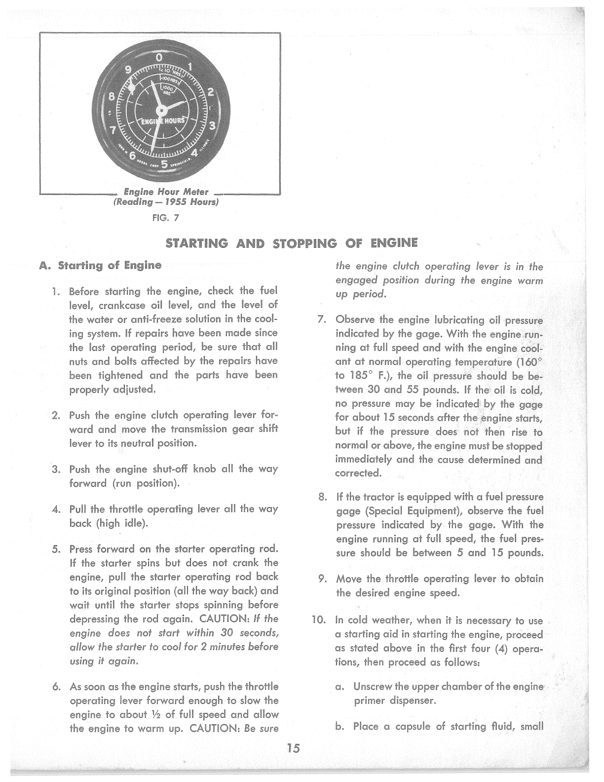
Engine Hour Meter
____
__.
(Reading-
1955 Hours}
FIG.
7
STARTING
AND
STOPPING
OF
ENGINE
A.
Starting
of
Engine
1.
Before starting
the
engine, check the fuel
level, crankcase oil level,
and
the level of
the
water
or
anti-freeze solution
in
the cool-
ing system.
If
repairs have been
made
since
the last
operating
period, be sure
that
all
nuts
and
bolts affected by the repairs ·have
been tightened
and
the parts have been
properly adjusted.
2.
Push
the engine clutch operating lever for-
ward
and
move
the
transmission
gear
shift
lever to its.neutral position.
3.
Push
the engine shut-off knob all the
way
forward (run position).
4.
Pull
the throttle operating lever all the
way
back (high idle).
5. Press forward on the
starter
operating rod.
If
the
starter
spins but does not crank. the
engine, pull the starter operating rod back
to
its
original position (all the
way
back)
and
wait until the starter stops spinning before
depressing the rod
again.
CAUTION:
If
the
engine does not start within
30
seconds,
allow the starter to cool for 2 minutes before
using it again.
6.
As
soon
asthe
engine starts, pushthe thrott~e
operating lever forward enough
to
slow the
engine
to
about
1h
of
full
speed
and
allow
the engine
to
warm up. CAUTION:
Be
sure
15
the engine clutch operating lever
is
in
the
engaged
position during the engine warm
up period~
7. Observe the engine lubricating
oil
·pressur,~,
indicated by the
gage.
With the engine\r~n~ '
ning
at
full
speed
and
with the
er1gine:
c:doi'.:'
ant
at
normal operating temperip(~re
{l~Q.P:
to 185°
F.),
the oil pressuf@
..
should
be
bJi
tween ·30
and
55 pounds.
If
the'\.
ofl
is
cotq,
no. pressure may
be
indicate~.J:>y the
ga.e
for
about
15
seco,nds
after
tf:ie'.i}ngine
stal'fs,
but
if
the pressure does;
not
then
rise to
normal or above, the engine must
be
stopped
immediately
and
the cause determined
am:I.
corrected.
8.
If
the tractor
is
equipped with a fuel pressul:e
gage
(Special Equipment), observe the fuel
pressure indicated by.
the
gage.
With the
engine running
at
full
speed,
the fuel. pres-
sure should be between 5
and
15
pounds.
9. Move the throttle operating lever to obtain
the desired engine speed.
10.
In
cold weather, when
it
is
necessary to use .
a starting
aid
in
starting the engine, pi:oceed
as
stated
above
in
the first four
(4)
opera-
tions, then proceed
as
follows:
a.
Unscrew the.upper chamber of theengine,,
primer dispenser.
b. Place a capsule of starti~g flui~,
smciH
,..,,
or large, dependi~g upon
the
atmos-
pheric
temperature
and
the
requirements
established by trial,
in
the lower
chamber
or
body
of
the
primer dispenser.
In
ex-
. tremely low temperatures, one
large
and
one small capsule may
be
necessary.
c.
Pull
the plunger
to
the
top
of the
upper
chamber
and
screw
the
upper
chamber
tightly onto the primer dispenser body.
d. Push the plunger to
the
bottom,
thereby
puncturing the capsule
and
releasing
the
starting fluid so
it
can
be
picked up by
the
primer pump.
e. Push the engine shut-off knob all the
way
forward
(run position)
and
pull the throt-
tle operating lever all the
way
back (high
idle position).
f.
Depress the
starter
operating
rod to
crank the engine,
and
at
the
same time
~
operate
the primer pump to force starting
.fluid into the engine
air
intake system.
Continue pumping,
after
the engine
starts, until all of the starting fluid
in
the
dispenser has been injected into the
air
intake system. CAUTION: ALWAYS
BE
SURE
THE
ST
ARTER
IS
CRANKING
THE
ENGINE
BEFORE
USING
THE
PRIMER
PUMP
TO
INJECT
ST
ART/NG
FLUID
INTO
THE
ENGINE
AIR
INT
AKE
SYSTEM.
g. While
the
engine
is
warming up, unscrew
the
upper
chamber
of
the
engine primer
dispenser, remove the empty capsule,
and
reinstall
the
upper
chamber.
CAUTION: The starting fluid contained
in
the cap-
sule
is
essentially ethyl ether, highly inflammable
16
af!d should
be
treatf!d with the same caution
as
high octane gasoline. Gelatine capsules dissolve
in
water
and
soften
at
high temperatures. Therefore,
the following precautions must
be
taken:
1.
Avoid breathing
large
quantities of the
fumes from the starting fluid.
2. Avoid. cutting of the
hand
by
barbs
on the
~uncturing plunger.
3. Avoid proximity of
the
starting fluid
and
capsules
to
open flames, sparks, or hot
surfaces.
4. Avoid contact of the. capsules with water.
5. Avoid subjection of the capsules to high
temperatures (above approximately 120°
F.).
Obtain
starting fluid capsules from your nearest
"Allis-Chalmers" Construction Machinery Dealer.
The capsules
are
packed, 12 of the
17
c.c.
or
24
of the 7 c.c. sizes,
in
a can for safe storage
and
handling.
Obtain
the size
and
quantity most
suitable for your needs according to the prevailing
atmospheric temperature.
B.
Stopping
of
Engine
Push the throttle
operating
lever all the
way
for-
ward
(low idle position)
and
allow the
engine
to
idle for
at
least 5 minutes, so
that
the engine may
cool
gradually
and
uniformly, then pull the engine
shut-off knob all the
way
back to stop the engine.
IMPORTANT:
ALWAYS SLOW
THE
ENGINE ·To
IDLING
SPEED
BEFORE
PULLING
THE
ENGINE
SHUT-OFF
KNOB
TO
STOP
THE
ENGINE. Cover
the exhaust
pipe
at
the
end
of
each
day's operation
to
prevent rain from entering while the tractor
is
idle.

'II.
AVOID
UNNECESSARY ENGINE IDLING
Prolonged engine idling causes the engine coolant
temperature
to fall below
the
specified·operating
range
of 160° to
185°
F.
Operating
with the
coolant temperature below this
range
is
detri-
mental to the engine, causing incomplete com-
bustion of fuel, which
in
turn causes crankcase
dilution
and
lacquer
or
gummy deposits ,to form
on valves, pistons, rings, etc.
It
also causes rapid
accumulation of sludge within the engine.
Since starting the engine
is
readily accomplished'
with
an
electric starter, there should
be
no reason
for prolonged engine idling. Stop the engine when
prolonged idling periods
are
necessary.
DRIVING INSTRUCTIONS
A.
Starting
of
Tractor
Start
the engine
and
allow it
to
warm up, then
slow the engine to idling
speed.
If
the engine
clutch has been
engaged,
disengage
it
and
push
forward on the clutch
operating
lever to force
the
clutch
brake
facing
against
the
brake
disc, thus
stopping the rotation of
the
transmission input
shaft. Move the transmission
gear
shift lever into .
the
required position· for
the
desired
speed
or
power.
Pull
the throttle
operating
lever
about
half-
way
back
and
pull back steadily on the engine
clutch operating lever until all slack
is
taken up ·
between the tractor
and
the
load, then pull the
lever back quickly to fully
engage
the clutch. After
the
engine clutch
is
engaged,
move the throttle
operating
lever to meet
the
operating
requirements.
Engagement of the engin~ clutch with
the
engine
running
at
half throttle
and
starting
the
load
in
the
above
manner
will
prevent excessi.ye
slippage
of
the
clutch, thus prolonging clutch life.
It
will
also
prevent "shock loading"
the
tractor.
To
shift to
another
speed
range,
push the engine
clutch operating lever forward
and
shift for
the
desired speed or power. When
the
engine clutch
operating
lever
is
pushed forward
it
forces
the
clutch
brake
facing
against
the
brake
disc, thus
stopping the rotation of
the
transmission input shaft.
Stopping the input shaft rotation enables
the
operator
to shift without clashing
the
gears.
To
shift to a higher
gear
after
the
tractor
is
in
motion, push the throttle
operating
lever forward
to the idle position
and
disengage
the engine
clutch. At the same time, shift to
the
higher
gear,
engage
the engine clutch,
and
pull the throttle
lever back to obtain
the
desired speed.
The engine dutch
operating.
lever controls
the
engine clutch which transmits power from the en-
gine to the transmission. Push the lever forward
to
disengage
the
clutch; pull it back
to
engage
the
clutch. The clutch
operating
lever also actuates a
shifting shaft locking device
in
the transmission.
When the clutch'operating lever
is
pulled back to
engage
the engine clutch it locks the transmission
"'
shifting shafts
in
the position to which
they
have
been moved
by
the transmission
gear
shift lever.
The clutch
operating
.Jever must
be
moved
tci
disengaged
position before the transmission
:~
.
shift lever
can
be
moved to shift the
gears
i~
neutral
or
into
another
position. '
Satisfactory
and
efficient ·operatron depends
largely on the operator's judgment
in
selecting .the
proper
gear
ratio
and
speed
for the various loads
or operation. Always
operate
the tractor
in
the
speed
range
that
will
permit the engine to
operate
at
full speed.
This
/will not only assure the most
power from
the
engine but will also allow the
engine to
operate
at
its highest efficiency.
CAUTION:
DO
NOT
SLIP
THE
ENGINE
CLUTCH
IN
AN
EFFORT
TO
PULL
AN
OVERLOAD;
SHIFT
TO
A
LOWER
GEAR.
The engine clutch should
engage
with a definite
over-center
"snap"
and
should require
an
appre-
ciable pull on the
operating
lever for
its
engage-
ment.
If
this
"snap"
is
not evident, or
if
the clutch
slips when under a load, adjustment must
be
made
immediately (refer to "ENGINE
CLUTCH
ADJUST-
MENT").
B.
Steering
of
Tractor
The
tractor
is
steered by disengaging the steering
clutch on the side of the
tractor
toward which the
turn
is
to
be
made.
This
is
do~e by using
the
steer-
.17

/
ing levers 101.ated directly
in
front of
the
tiperator.
To
mcike
a right turn, puU ,back the righ,t-hand
ste,efing lever;
to
make a left turn, pull back
.~the
left-hand steering lever. With
the
left steering
0
dutch
disengaged,
power
is
not delivered to the
, left track
and
the
track ~ill
·slow
down or stop.
Since power
is
still being delivered to the right
track, the right track.
will
keep turning
and
cause
the
tractor
to
turn to the left. When the right
steering
dutch
is
disengaged,
the
tractor
will
turn
to
the right
in
a similar manner.
If
a short turn
is
to
be
made,
pull the steering
lever back on
the
side
toward
which
the
turn
is
to
be
made
and
press down on the corresponding
brake
pedal;
this
will
stop
the
track completely.
Always pull
the
steering lever all the
way
back
when turning.
When
the
tractor
.has turned
as
desired,
return
the
lever immediat"ely to
its
forward
'position. Disengage
and
engage
the
steering
dutc;:h~st,smoothly
and
completely
to
avoid exces-
···•·
f?siv.el·~ar on
the
dutch friction discs.
~;,'
;':{
'}
'\)):/£'£:!:,
':
;
'>"
,J.''(:,'
,:,'4'.11
,:~:~~ti;steerfog
the
tractor
dc;,wn
steep
grades
with
.the lpqd
pushing·the
tractor,
the
use of
the
steer-
.ing levers
is
opposite to
that
when pulling a load.
lh
this case,
the
left-hand steering lever
is
used
to
mak,1a iright
twrn
and
the right-hand steering lever
to
make a left torn. Disengaging either steering
dutch
wiU
allow the
track
on
that
side
to
travel
faster, since
the
br.aking ,power of the engine
is
released from it, while the steering dutch remain-
ing
engaged
will
ad
as
a.
brake
for the opposite
.track.
During operation, observe the
amount
of
free travel
of
the
steering levers (the distance the levers move
before pressure
is
felt
and
disengagemenf
of dutch
begins).
This
free travel,. which assures complete
engagement
of
the
steering dutches, should
be
from l to 3 inches, measured
at
the tops of
the
levers, When'the free travel of either steering lever
becomes less than l inch,
the
steering dutch
linkc;1ge
requires adjustment (refer to "STEERING
CLUTCH
LINKAGE
ADJUSTMENT").
C.
Stopping
of
Tractor
To
stop the tractor, push
the
throttle operating
lever forward
and
disengage
the
engine dutch by
pushing the dutch operating lever forward, then
press on the
brake
pedals
to
apply
the brakes.
If
the
tractor
is
parked
on a
grade
where there
is
a
possibility of
its
rolling, lock
the
brake
pedals
in
their
applied
position by the use of the parking
brake
lock levers. Allow the engine to idle
at
least
5 minutes so
that
the engine
will
cool gradually
and
uniformly, then pull the engine shut-off knob
all the
way
back to stop the engine.
IMPORTANT:
ALWAYS
STOP
THE
ENGINE WHEN
PROLONGED IDLING
PERIODS
ARE
NECESSARY.
This
will
not only save fuel
and
unnecessary
wear
on the engine but
will
also avoid operating the
engine below normal
operating
temperature.
If
it
is
necessary to keep
the
engine running, it.should
be
run
at
a
speed
fast enough
to
maintain normal
engine
oil
and
fuel pressure
and
with the engine
dutch
engaged.
While operating the tractor, observe
the
action of
the
b.rakes. The brakes
are
properly adjusted when
the
brake
pedals
each
have approximately l%
to
2 inches of free travel (refer
to
"STEERING
BRAKES").
The brakes require adjustment before
they become loose enough
to
allow the
brake
pedals
to strike the floor
plate
when the brakes
.
are
fully applied.
If
the
brakes
are
properly
ad-
justed,
and
still
do
not hold, it may
be
due
to
oil
on the
brake
linings
and
the brakes
will
require
washing.
Refer
to
"WASHING
STEERING
CLUTCHES"
for instructions on washing the brakes
and
steering dutches.
18

The
slee1dni.:1,
·
ceimp1:irtmerrb,
cire
dn::iino!:Je
,,;:,,f
i:::my
h,,ies
or·
wah':':i".
/~1;
si·eering diJ,tch
compartme1r11t
cfrc1in
hole (Fig. 52)
is
!oo::ited
fr,
th,a
boHom of
dutch
cornpo;rtmen't.
The
en•f1ine
rrienl'
cmd
1s
l",l',,"!i''IC•i"ii
in
the
bofh::itn ,:,f
"tl1•8
cm
(r0fr1r
to
hc,s1~~s
'io
pn:rJ·ecil' lt
frnffi
SYST!c':1\i\
1
').
und
-:md
r9,.
T1::isi·
pr,epc::1n2:
''C()LD
VV'E:ATHEl;i:
ENG!l,,iE
Pml,/lE!l'"
for
tD50
CJS
Sf)IXJ
CIS
indk,::r[·t'H,
ri!:iqi,iired.
Prrovide,
c1
rcidk~l·ot
(:,c::;rnpciri·nr,ent
H
the
to
mc1iurhc1in
i·he
,?n~
tr:crnnpernh.ir,a,
'Ntthin
ths
cmd fr,r sides
o-f
t!H':,
th1srir1os"!"u1"tr,.
gr,nie
rr.mge
e,i:framdy dusty
l),
scmdy
ci:::inditi::mz,
1/~
dro1n
p!VfJS
with lrc1d,cir) shou,ld be
V1
lhen
,o,p.ercrhn£i
wiih th~ drciin plug:ii im;tcdiad,
n,Hno·,i1,::i
Ih,e
piug.s
to
,oi!
Hm,·
,:1ccunmk:1ied
in
it
from
getl'ing on
brc;ke lining:s
..
if
'!'he
l'n'.:l,dC1l"
ren1ahls idki
c.1'!'
ge:o,d
pi·'(1:Ct2it:E~
t,(),
r1B:tT)
1
0,\1
1e
'!he d1J)' reinstc1l1
tn::1ctc,u'
the
mn,t
t,kir'l'ing
1:Jif
c1
"DIESEL"
,1:HJ1Jim'<
lTH,::rn,s
cc:m
be
d::rhJ11n~d
sp,aec!,
bcdt,edeis,
:,h::1ri"'2,r,
open:rted
in
y1r:,1JJ
r
nta(~
lft85'·t
1t:11
tJth
,c:1(li.1..:ed
t
11
~'°
for
!nform.::iticm1
rEJl}mdintJ
o::ivciik,,,
fhe
ope·rofin;\Ji
Nhiffe
frm:for
is
idle,
sr...ffidiy
f.'J
ihe
gn:nm,d,
or
fr·,adrs,
ccruss:d
by
cm ,,:,iff&mpf
1c,
trnci<s.

ENGINE COOLING
SYSTEM
A.
Qp~,ription
of
System
The engine cooling system includes the
water
pump,
radiator,
engine
oil cooler, thermostats, engine
temperature
gage,
cooling fan,
and
the
water
passages
in
the cylinder block
and
cylinder
head.
The
water
pump
draws
the
coolant
from the bottom
of
the
radiator
and
circulates it through the engine
oil cooler
and
through the
water
passages
in
the
engine. The
coolant
is
discharged
from the cylinder
head
into the
water
outlet manifold
and
passes
througn' the thermostat housing
and
the
radiator
inlet elbow to the
upper
part
of the radiator. The
fOolant
is
cooled
as
.it
passes from the
top
to the
bottom,of the
radiator
core by
air
drawn
through
\h~
radiator
co.re
by
the suction-type cooling fan.
Th,~
th~ric1nristats,
located
in
the thermostat housing
t.if
the front of
the
water
outlet manifold of the
engine,
operate
automatically to maintain a normal
coo.lant
operating
temperature
of
160°
to
185°
F.
'B.
General
Maintenance
Jn
warm weather, keep the cooling system filled
with
dean
sofrwater
or
rain
water
whenever pos-
sibie.''llf softw!!iler
is
not
available
and
hard
water
must
be
used, tire
hard
water
should first
be
treated
with a
water
softener. A commercially reliable rust
inhibitor should
be
added
to the cooling system for
warm
weather
operation. A rust inhibitor (soluble
oil), available
in
half pint
or
quart
containers, can
be
ol:itained from "Allis-Chalmers" Dealers
and
should
He
added
to
the cooling system
in
propor-
tions
of
1·pint of soluble
oil
to every 15 quarts of
water.
C!>,UTION:
NEVER
ADD
AN
ANTI-FREEZE
SOLUTION
TO
A COOLING
SYSTEM
THAT
CON-
TA/NS A
RUST
INHIBITOR. Drain, flush,
and
refill
the
cooling system with clean
water
before
adding
an
anti-freeze solution for cold
weather
operation.
In
winter
weather,
use
an
ethylene glycol anti-
freeze
solution
in
the system to protect
against
damqge
from freezing.
This
type
of anti-freeze has
a much higher boiling point
than
water. After
any
addition of
water
or
anti-freeze compound, test the
solution
after
the
added
quantity has become
thoroughly mixed to make sure it
will
withstand
the
prevailing or anticipated
temperature.
A
mix-
ture
of
60%
ethylene glycol
and
40%
water
will
20
provide maximum protection;
the
use of more
than
60%
ethylene glycol
in
the
solution will raise the
freezing point
and
provide less protection
against
freezing.
Keep the
radiator
air
passages
free from leaves,
trash,
and
other material which will restrict the flow
of
air
through
the
radiator.
All
leaks
in
the cooling system must
be
corrected
as
soon as they
are
evident. The fan drive. belts
and
the
water
pump
and
generator
drive belt must
be
kept properly adjusted.
The most efficient engine operation
is
obtained
with the coolant
operating
temperature
held within
a
range
of
160°
to.
185°
F.
Operating
the engine
with the coolant
temperature
below this
range
will
result
in
incomplete combustion
of
fuel, higher fuel
consumption with less power,
and
will
cause harm-
ful
deposits within the engine.
Maintaining the normal
coolant
op~rating tem-
perature
(160° to
185°
F.)
depends
mostly on
proper
functioning of the thermostats.
If
the coolant
te,;,perature remains consistently below normal,
the thermostats should
be
removed, checked for
proper
operation,
and
replaced
if neces;;ary.
C.
Draining
of
Cooling System
Remove the
radiator
filler
cap
and
open the cyl-
inder block
drain
cock, located on the right
rear
side of the cylinder block.
Open
the
radiator
drain
cock, using the extension tool (included with 'the
tools fur~ished with the tractor) inserted through
the hole
in
the lower right corner of the main frame.
CAUTION: When draining the cooling system
in
freezing weather,
make
certain that the coolant
flows freely from all drain cocks
and
that the
system drains completely.
D. Filling
of
Cooling
System
Close the
radiator
drain cock, located
at
the lower
right corner of the
radiator
(in the
water
outlet
elbow). Close the cylinder block drain cock, located
in
the right
rear
side of the cylinder block.
Fill
the
cooling system through the
radiator
filler
cap
opening until the coolant level
is
within approxi-

Cylinder
B.lock
Drain
~q~/$
~1',J
Radi~tor
Drain Cock location.
FIG.
8
FIG.
9
mately 2 inches of the
top
of the
radiator
and
install the
radiator
filler
cap.'
E.
Fc~an
Drive
Belt
Adiustment
The fan drive belts
are
correctly adjustic:1 when
the
straight side of the belts
can
be
pressed inward
by
hand
approximately
Y2
to % inch
at
a point
half-way between the crankshaft
and
the fan
.
21
~=;;..:
Water
Pump
and
Generator
Drive
Self
·
Adjustment
foc~tion
FIG.
10
pulleys.
To
adjust the drive
bE!lts1
loosen. th
idler
bracket
clamping capscre~."~'J-\9~en
the
nut on the adjusting screw
and
turn/lf~:~:adj.ust
....
screw
in
or
out
as
necessary to obtain'.fli}c;_orr~c:t
tension on the drive belts, then tighte~;tthti.fifdjost-
ing screw jam nut. Tighten
the
..
fall
idJiji'li
btfu9~1et
clamping capscrew.
F.
Water
Pump
and
Genercator
Dri
e
Belt
Adiustment
The
water
pump
and
generator
drive. belt
is
prof
erly adjusted when the belt ~an
be
pressed inward
by
hand
approximately
Y2
inch
at
a point half-way
between the
generator
and
water
pump pull,eys.
To
adjust the drive belt, loosen the
generator
adjusting
arm
capscrew, move the
generator
up
or down to
obtain
the correct tension of the drive
belt, then tighten
the
adjusting arm capscrew.

FUEL
SYSTEM
A.
DESCRIPTION
OF
SYSTEM
The engine fuel system consists of a fuel tank, first
stage
fuel filter, fuel transfer pump, second stage
fuel filter, fuel injection pump, fuel nozzles, and
the fuel· lines. There
are
two fuel pressure systems;
the low, pressure system
and
the high pressure
system.
The
low
pressure system consists of the fuel tank,
first
stage
fuel filter, fuel transfer pump, second
stage
fuel filter, fuel leak-off
header,
and
the fuel
return line leading from the fuel sump of the fuel
injection pump to the fuel tank.
The high pressure
sy;~tem.
consists of the fuel
in-
.d!~!ion pump, fuel n~zzles,
and
aU high pressure
'•
fpll'Jines connecting tlie fuel injectfor, pump to the
(uei
no:µles.
The
high pressure fhel
lin~s
are
s~c:imles!i
ste.el
tubing
and
each line
is.
the same
l~ngth. These. lines being the same length assures
·
thil$tQper
timing
and
the
proper
amount of fuel
·tq~.ach fuel nozzle. These lines
are
not interchange-
·~i,fo;
when ordering lines·
for·
replacement, specify
,f\•,.:•.i
.,.
\ . /
'f9r
;~~ic;h
cylit!d~r the line
is
ordered.
. .
Tl,e,f~~Fis draWh from the fuel tank, through the
Ji:r~fstag(?. f~eF;filter, by the fuel transfer pump.
·The fuel tis th~n .forced by the transfer pump,
through the second stage}uel filter
and
to the fuel
inj~ction pump.
The
amount of fuel required for
~o,:nbustion.
is
forced under high pi:essure by the
fuel injection pump, through the high pressure fuel
FUEL
PRESSURE
RELIEF
VALVE
ENGINE
lines to the fuel nozzles, from which the fuel enters
the engine combustion chambers
in
the form of a
fine cone-shaped spray.
There
is
a certain amount of fuel
seepage
between
the
lapped
surfaces of each fuel nozzle
va.lve
and
its
body, which
is
necessary for lubrication.
This
leakage
of fuel accumulates around the spindle ·
and
in
the spring compartment of each fuel nozzle,
and
is
returned through the leak-off
header
to the
fuel return line, extending to the fuel tank.
The
excess fuel delivered to the fuel injection pump by
the fuel transfer pump
is
returned to the fuel tank
through the fuel return line. A pressure of 5 to 15
P.S.I.
is
maintained within the low pressure fuel
system by a fuel pressure relief valve installed
in
the fuel return outlet of the fuel injection pump.
The heavy-duty fuel injection pump
is
of the con-
stant-stroke, distributing-plunger, sleeve control
type, the plunger being actuated by a cam
and
tappet
arrangement
which also carries the gearing
for the distribution function.
Its
purpose
is
to meter
the fuel accurately
and
deliver
it
precisely
at
a
definite moment
in
the engine cycle
and
under
high pressure to the fuel nozzles.
The
fuel injection
pump plunger
is
9
M.M.
in
diameter and the pump
is
controlled by
.a
mechanical-centrifugal type
(type·
"C'?
governor).
The function of the fuel nozzles
is
to direct the
metered quantity of fuel, received from the fuel
injection pump, into the engine combustion cham-
TO
FUEL
PRESSURE
GAGE
(SPECIAL
EQUIPMENT)
r1 1
SECOND
ST
AGE
FUEL
FILTER
FUEL
TRANSFER
PUMP
FIRST
STAGE
FUEL
FILTER
-
FUEL
TANK
Loo--------------
Fuel Flow -Schematic
Diagram
--------------'
FIG.
11
..
22
Table of contents
Other Allis-Chalmers Tractor manuals

Allis-Chalmers
Allis-Chalmers G User manual

Allis-Chalmers
Allis-Chalmers B Install guide

Allis-Chalmers
Allis-Chalmers HD-5 User manual

Allis-Chalmers
Allis-Chalmers regent hydro 14 User manual

Allis-Chalmers
Allis-Chalmers H 4 Specifications

Allis-Chalmers
Allis-Chalmers 10 hp User manual

Allis-Chalmers
Allis-Chalmers WD Use and care manual

Allis-Chalmers
Allis-Chalmers ac130 series User manual

Allis-Chalmers
Allis-Chalmers HD-4 Specifications

Allis-Chalmers
Allis-Chalmers G User manual


 Service manual")


