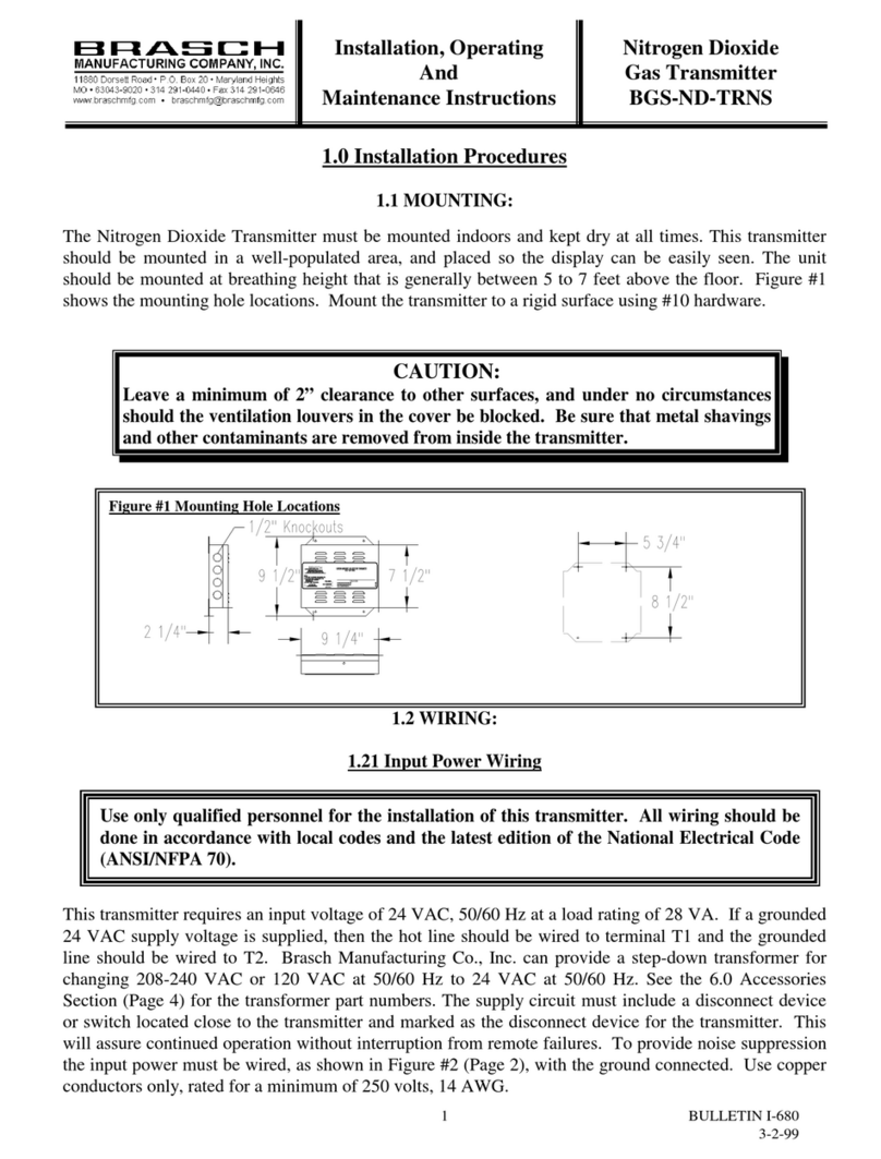
Brasch TRNS Generation 2 User manual

Brasch Environmental Technologies, LLC
140 Long Road, Suite 101
Chesterfield, Missouri 6 005
14-291-0440
www.braschenvtech.com
TRNS Generation 2
Installation / Operation Manual

Table of Contents
Introduction...................................................................................................................................4
General Description..................................................................................................................4
Features and Benefits..............................................................................................................5
Technical Specifications................................................................................................................6
Product Specifications..............................................................................................................6
Target Gas Specifications.........................................................................................................7
Carbon Monoxide.................................................................................................................7
Nitrogen Dioxide...................................................................................................................7
Description of Front Panel Indicators.......................................................................................8
Front Panel Indicators..........................................................................................................8
Operation Safety Notice................................................................................................................9
Types of Notices.......................................................................................................................9
Quick Start Guide.......................................................................................................................10
Step 1 – Mounting..................................................................................................................10
Step 2 – Input Wiring..............................................................................................................10
Step – Output Wiring...........................................................................................................11
Step 4 – Applying Power.........................................................................................................11
Installation...................................................................................................................................12
Mounting the Transmitter........................................................................................................12
Connecting the Power Supply................................................................................................1
Connecting the Voltage or Current Proportional Output........................................................14
Connecting the Modbus Output..............................................................................................15
Applying Power For the First Time.........................................................................................15
Installation Diagrams..............................................................................................................16
Operation....................................................................................................................................18
How the Transmitter Senses the Target Gas.........................................................................18
Factory Default Settings.........................................................................................................18
Using the Analog Proportional Output....................................................................................18
Adjusting the Proportional Output..........................................................................................19
Obtaining the Best Operation.................................................................................................19
Carbon Monoxide and/or Nitrogen Dioxide Transmitters...................................................19
Maintenance...............................................................................................................................20
Testing the Response to the Target Gas................................................................................20
Carbon Monoxide or Nitrogen Dioxide Transmitters..........................................................20
Replacing the Sensor.............................................................................................................21
Suggested Repair Parts.........................................................................................................22
Troubleshooting..........................................................................................................................22
Fault........................................................................................................................................22
Checking and Replacing Fuses..............................................................................................22
Common Installation/Operation Mistakes..............................................................................2
Proportional Output Connected Incorrectly........................................................................2
Setting the Proportional Output Incorrectly........................................................................2
IOM02
Rev 1.0 – December 22, 2020 2

Using Improper Resistance/Impedance.............................................................................2
Transmitter Mounted in an Unsatisfactory Location..........................................................2
Limited Warranty.........................................................................................................................24
Warranty Statement...........................................................................................................24
Service and Repair Procedures.........................................................................................24
Appendix.....................................................................................................................................25
Model Numbers and Descriptions..........................................................................................25
Transmitter Model Number and Description......................................................................25
Figures and Diagrams............................................................................................................25
IOM02
Rev 1.0 – December 22, 2020

Introduction
General Description
The Brasch Environmental Technologies TRNS Generation 2 Gas Transmitter is designed to
function as a gas sensor and signal transmitter. The transmitter consists of a sensor and
digital control circuitry. A linear proportional output circuit is able to provide analog signals to a
customer-supplied building management controller or a variable-frequency drive. An RS-485
circuit is able to provide two-way digital communication using Modbus RTU. A microprocessor
monitors the signal from the sensor and transmits that signal to the output as either an analog
or digital signal.
The sensor used in the transmitter operates on the electrochemical principle. A current is
produced when the target gas reacts chemically with an electrode inside the sensor. This
small current is changed to a voltage by the transmitter’s circuitry, amplified, and converted to
the proper output signal. This signal is proportional to the target gas concentration present at
the sensor.
The transmitter’s circuitry consists of a printed circuit board mounted inside a polycarbonate
housing. The housing has a NEMA R rating. Vents are located on the bottom and side of the
housing to allow the sensor access to ambient air.
IOM02
Rev 1.0 – December 22, 2020 4

Features and Benefits
•Comprehensive Monitoring
◦Detects CO and/or NO2
•Greater Coverage
◦Monitors up to 9,000 sq. ft.
•Enhanced Durability
◦Rainproof Water Resistance
◦Simple Service and Maintenance
•Simplified Installation
◦Preconfigured Wiring
◦Factory Calibration
◦Customized Programming
•Versatile Communication
◦Analog Output via User-Selectable Current or Voltage Loop
◦Digital Output via Modbus RTU Communication Protocol
•Effortless Upgrade
◦Works with New and Existing Building Controls Systems
◦Fully Backwards Compatible with TRNS Generation 1
IOM02
Rev 1.0 – December 22, 2020 5

Technical Specifications
Product Specifications
Input Power 24 VAC, 50/60 Hz, 0.25 A
Installation Category II (local level, over-voltage transients less than 500V)
Storage Temperature -50°C to 120°C (-58°F to 248°F)
Operating Temperature -20°C to 50°C (-4°F to 122°F)
Humidity 10% to 90% (non-condensing)
Ventilation Control Relays None
Internal Alarm None
Front Panel Indicators Power (green LED)
Fault (yellow LED)
Display None
Selectable Fan Settings None
Alert Levels None
Delay Times None
Dimensions 4.8” W x 4.72” H x 2.16” D (12.2 cm W x 12 cm H x 5.5 cm D)
Weight 1 lbs (0.5 kg)
Housing Gray, NEMA R, polycarbonate plastic
Compliance ANSI/ISA 92.00.01-2010 (R2015)
EN 50270
FCC Part 15 Subpart B
RoHS
IOM02
Rev 1.0 – December 22, 2020 6

Target Gas Specifications
This Brasch Gas Transmitter is available for monitoring carbon monoxide and/or nitrogen
dioxide as target gases. Regulatory agencies have determined the threshold concentrations at
which the gases become dangerous. Brasch Environmental Technologies, LLC has designed
their transmitters so that the measurement ranges for each target gas meet the agencies’
requirements. Each target gas, for which Brasch currently produces a transmitter, is listed
below along with the relevant concentration specifications.
Carbon Monoxide
Full Scale Span: 200 PPM
Resolution: 1 PPM
Minimum Accuracy*: ± 10% or 6 PPM
Expected Lifespan 10 years
Recommended
Recalibration Time 2 years
Nitrogen Dioxide
Full Scale Span: 10 PPM
Resolution: 0.1 PPM
Minimum Accuracy*: ± 15% or 0.8 PPM
Expected Lifespan 10 years
Recommended
Recalibration Time 2 years
*Allowable tolerance for accuracy and repeatability criteria as defined in Annex A, Item 2 of ANSI/ISA 92.00.01-2010 (R2015)
IOM02
Rev 1.0 – December 22, 2020 7

Description of Front Panel Indicators
The front panel indicators convey to the user the operational status of the transmitter. The
following table describes the function of each indicator. Please refer to the transmitter’s front
panel label for the indicator’s location.
Front Panel Indicators
Indicator Color Description
Power Green Glows whenever power is on
Fault Yellow Glows when expected end-of-life is reached
IOM02
Rev 1.0 – December 22, 2020 8

Operation Safet Notice
Certain procedures and operations detailed in this manual require that specific precautions be
taken prior to beginning the procedure or operation. When precautions are required, a notice
will be printed in an appropriate location in the manual. The user is urged to read and
understand all such notices.
T pes of Notices
Three types of notices may be used in this manual to describe the severity of the situation
encountered.
WARNING: This notice indicates that conditions exist that could cause personal injury
or loss of life.
CAUTION:Conditions exist that could cause damage to the equipment or other
property.
Note: Special consideration should be given to the procedure or operation,
otherwise an unexpected operational result could occur.
IOM02
Rev 1.0 – December 22, 2020 9

Quick Start Guide
Please read this entire manual before attempting to install and operate this gas transmitter.
This guide is only intended to provide the basic steps necessary for installation and operation.
Each step will reference the portion of the manual where more complete information can be
obtained.
Step 1 – Mounting
Determine the location for mounting your transmitter(s). The location(s) may be indicated on
the architectural drawing. Also, the owner or designer of the facility may be consulted.
Mounting guidelines can be found on page 12 of this manual.
Step 2 – Input Wiring
Provide a dedicated circuit at the required 24 VAC and 6 VA at each transmitter mounting
location. Follow all national and local wiring codes. The wiring should be at least 14 AWG. A
conductor connected to earth ground should also be provided. The circuit must include a
disconnect switch located within easy reach of the transmitter.
Color-coded wires exiting the transmitter housing through the top conduit connector are
provided for connecting the operating voltage to the transmitter. Therefore, it should not be
IOM02
Rev 1.0 – December 22, 2020 10
WARNING
This transmitter may require the use of voltage levels high enough to cause fatal injuries.
Proper procedures must be followed any time work is performed on this unit.
Only qualified personnel should attempt to install, maintain, or service this equipment.
CAUTION
Operating this transmitter with the incorrect voltage and power requirements can cause
internal electrical components to overheat and fail. Operation with the wrong power
requirement will void the manufacturer’s warranty and the installer will be responsible for any
damage that occurs.
Contact Brasch Environmental Technologies, LLC before connecting power to the transmitter
if you are unsure of the correct power requirement.

necessary to remove the front cover from the transmitter when connecting the voltage supply.
Connect the hot power conductor to the black wire and the neutral conductor to the white wire.
Refer to page 1 for further information.
Step 3 – Output Wiring
The transmitter conveys its sensor signal over two wires. Use a two-conductor shielded cable
for each transmitter in the system. As with the input power connections, color-coded wires exit
the transmitter housing through the top conduit fitting so removal of the front cover should not
be necessary. When using the analog output, the positive conductor connects to the red wire
and the reference conductor connects to the green wire. When using the digital output, the
positive conductor connects to the brown wire and the negative conductor connects to the blue
wire.
See figures 1 and 2 on page 16 for wiring diagrams.
Step 4 – Appl ing Power
Once you are sure that the wiring connections are correct, apply power to the transmitter
circuit. When power is first applied, the green power indicator will glow, indicating the
transmitter is active. The unit will begin transmitting its signal through the output immediately;
however, you should wait at least 2.5 minutes before taking any gas measurements as the
sensor will still be warming up.
See page 15 for more information concerning the initial startup.
At this point, the transmitter is now ready to monitor for the presence of the target gas.
IOM02
Rev 1.0 – December 22, 2020 11

Installation
Mounting the Transmitter
The ability of the transmitter to sense the target gas depends greatly upon proper selection of
the mounting location. This transmitter monitors the area around it by sampling the air that
passes by the sensor. Since the sensor is mounted inside a housing, air must diffuse through
the intake vent and pass by the sensor on its way out the exhaust vent. Therefore, the
transmitter should be positioned where it can sample air that contains a target gas
concentration representative of the average value in that area.
When determining the mounting location, give special consideration to the following guidelines.
•Use one sensor per target gas for each area to be covered.
•Always prioritize locations with the highest occupation density.
•The types of gases each unit is designed to monitor have densities approximately equal
to that of air. For maximum safety, mount the unit at the average breathing height –
approximately 5 to 7 feet from the floor.
•Avoid mounting locations that would not be representative of the average gas value in
that area. These include but are not limited to locations near doorways, fans, ventilation
inlets and outlets, and areas with air velocities in excess of . ft/s (1 m/s).
•Avoid locations that would allow direct contact with water. Mounting the unit near
outside garage doors may allow rain to hit the unit when the door is open.
•Avoid locations that are directly in the outlet air vents of heaters or air conditioners.
•Avoid mounting locations with normal ambient temperatures below -4°F (-20°C) or
above 122°F (50°C).
•Do not allow exhaust from engines to flow directly on the unit. Each unit is designed to
sense gas concentrations that are 00 to 1000 times less concentrated than the gas
levels found in engine exhaust. Also, engine exhaust contains high levels of other
components. These components can shorten the useful life of the sensor if they contact
the sensor before being diluted by the room air volume.
•Avoid mounting locations where the unit may be hit by passing vehicles. If the unit must
be mounted in these locations, provide a shielding cage around the unit for protection.
•Do not restrict the air flow to the unit housing.
•Do not mount the unit in a corner.
IOM02
Rev 1.0 – December 22, 2020 12

•Do not mount the unit near containers of chemicals such as gasoline, kerosene, alcohol,
or other cleaning fluids. High level concentrations of these chemicals may be mistaken
as the target gas by the sensor and cause false readings. Also, some welding gases
may cause false readings.
The transmitter is attached in the mounting position in one of three ways.
•Attach the housing to conduit using appropriate conduit fittings. If you use this method,
make sure that the conduit is securely attached to a solid support. Firmly tighten the
threaded nuts on the conduit fittings inside the transmitter housing so they will not
loosen over time.
•Attach the housing to a four inch square conduit box using the ½ inch fitting provided
with the transmitter. Make sure that the conduit box is firmly fastened to the mounting
surface with screws. Securely tighten the fitting nut on the inside of the conduit box so it
will not loosen over time.
•Attach the housing to a solid support base using screws through the internal housing
mounting holes. This method requires removal of the housing cover to gain access to
the mounting holes. A mounting hole is located at the top and bottom of each housing
end wall.
Find a flat area at least 6 inches high by 6 inches long and place the back of the open
housing flat against it. Using a pencil or other slender marking tool, mark the location of
the four mounting holes using the housing as a template. Start the screws without the
housing in place to avoid any possibility of damage to the housing or circuit boards.
Remove the screws, place the housing in position, and install the mounting screws. Do
not over-tighten the screws as this may crack the plastic housing. Be careful not to
damage the printed circuit board. Carefully replace the housing cover and securely
tighten all four of the cover retaining screws.
Connecting the Power Suppl
While this transmitter does not require much power to operate, it is usually located near
machines that do consume large amounts of power. When these large machines operate, they
IOM02
Rev 1.0 – December 22, 2020 1
WARNING
This detector may require the use of voltage levels high enough to cause fatal injuries.
Proper procedures must be followed any time work is performed on this unit.
Only qualified personnel should attempt to install, maintain, or service this equipment.

cause large voltage spikes to appear on the AC wiring. These spikes can interfere with the
proper operation of the transmitter. The easiest way to avoid much of this interference is by
providing power to the transmitter through a dedicated circuit from the service panel. In some
very noisy situations, a line filter can be connected in the power supply circuit just ahead of the
wiring connections at the transmitter.
Provide a dedicated circuit at the required operating voltage at each transmitter mounting
location. Follow all national and local wiring codes. The wiring should be at least 14 AWG. A
conductor connected to Earth ground should also be provided. The circuit must include a
disconnect switch located within easy reach of the transmitter.
Be sure that the step-down transformer provides 24 VAC and has at least a 6 VA rating. The
power requirements for the transmitter are also listed on the label on the left side of the unit.
Color-coded wires exiting the transmitter housing through the top conduit connector are
provided for connecting the operating voltage to the transmitter. Therefore, it should not be
necessary to remove the front cover from the transmitter when connecting the voltage supply.
Connect the hot power conductor to the black wire and the neutral conductor to the white wire.
Connecting the Voltage or Current Proportional Output
The Brasch Gas Transmitters include circuits that provide either a current loop or voltage
proportional output for each gas sensor. Each output produces a linear response over the full
scale range of the sensor. A detailed description of these outputs can be found starting on
page 18.
IOM02
Rev 1.0 – December 22, 2020 14
Note
Do not operate the transmitter on the same AC circuit with the ventilation components.
Doing this will almost always cause improper transmitter operation.
CAUTION
Operating this transmitter with the incorrect voltage and power requirement can cause
internal electrical components to overheat and fail. Operation with the wrong power
requirements will void the manufacturer’s warranty, and the installer will be responsible for
any damage that occurs.
Contact Brasch Environmental Technologies, LLC before connecting power to the transmitter
if you are unsure of the correct power requirement.

The transmitter conveys its sensor signal over two wires. Use a two-conductor shielded cable
for each transmitter in the system. As with the input power connections, color-coded wires exit
the transmitter housing through the top conduit fitting so removal of the front cover should not
be necessary. At each transmitter, the positive conductor connects to the red wire and the
reference conductor connects to the green wire.
See figure 1 on page 16 for a wiring diagram.
Connecting the Modbus Output
The Brasch Gas Transmitters also include a circuit that provides digital communication via
Modbus RTU protocol. This output allows a client device to read the firmware version, gas
sensor type, gas sensor value, and any error codes associated with the transmitter. Color-
coded wires exit the transmitter housing through the top conduit fitting so removal of the front
cover should not be necessary. At each transmitter, the positive conductor connects to the
brown wire and the negative conductor connects to the blue wire.
See figure 2 on page 16 for a wiring diagram. A more complete description, including
instructions on setting up the client, is available in the dedicated Modbus Setup Guide.
Appl ing Power For the First Time
Once all the wiring connections are complete, the transmitter is ready for power to be applied.
The green power LED will glow immediately and the output will begin transmitting. However,
the first 2.5 minutes after the power is applied should be considered a warm-up period as the
sensor readings will not be fully stabilized yet. After this time, the transmitter is ready to
monitor the area for target gas.
IOM02
Rev 1.0 – December 22, 2020 15

Installation Diagrams
IOM02
Rev 1.0 – December 22, 2020 16
Figure 1: Wiring – Analog Output Configuration
Figure 2: Wiring – Digital Output Configuration

IOM02
Rev 1.0 – December 22, 2020 17
Figure : Wiring – Remote Sensor Configuration

Operation
How the Transmitter Senses the Target Gas
Ambient air surrounding the transmitter housing diffuses inside the housing where it comes
into contact with the sensor. Although the transmitter’s circuitry dissipates very little power, a
small amount of heat is produced inside the housing. This heat causes air to rise up through
the bottom vent, past the sensor, and out the upper vent. Any target gas present in this air
causes a response from the sensor. If the transmitter is located properly, the sensor will
respond to the average amount of the target gas present in the area. For help in properly
locating the transmitter, please read the mounting guidelines on page 12. This transmitter
monitors the actual concentration of the target gas exposed to the sensor. This actual value
may be different than the time-weighted-average values displayed by many personal gas
monitors. Please take this difference into account when comparing the response of the two
units.
Factor Default Settings
Unless otherwise specified on the order form, the following settings will be used to configure
the analog proportional output of the transmitter.
Setting Default
Analog Proportional Output Units mA
Analog Proportional Output Signal 4-20 mA
Using the Analog Proportional Output
This Brasch Gas Transmitter is supplied with a linear proportional output that can be
connected to a building management controller or variable-frequency drive. This output can
produce either a current or voltage signal that is proportional to the concentration of the target
gas present at the sensor. By moving jumpers, located on the bottom, right corner of the
printed circuit board, the user can select from 4-20 mA, 2-10 VDC, 1-5 VDC, and 0.2-1 VDC
signals. This signal is available at the terminal strip TS , located at the bottom, right corner of
the board. See figure 6 on page 26 for the terminal strip locations and signal mode selection
jumpers.
Unless otherwise specified, the transmitter is shipped from the factory with the selection
jumpers set in the 4-20 mA current loop mode. To change the mode to one of the voltage
modes, the JP2 selection jumper must be moved to the “Volts” pins. After this, the JP jumper
IOM02
Rev 1.0 – December 22, 2020 18

may be moved to the desired output. To return to the 4-20 mA mode, replace the JP jumper
on the “mA” pins and the JP2 jumper to the “4-20 mA” pins. Ensure that power to the
transmitter is off before attempting to change these settings.
The output signal is connected using a two-conductor shielded cable. The resistance of the
total cable length must be less than 250 Ω if the 4-20 mA current loop mode is selected. For
the voltage modes, the input impedance of the controller must be greater than 100 kΩ.
Ground the shield of the signal cable at an earth grounding point only to avoid noise conditions
created by ground loops. Although the positive signal lead can be shorted to ground without
causing damage, this condition should be avoided. Also, do not route the signal cable in
conduit containing other wiring to avoid unwanted noise pickup.
The linear outputs produce a signal based on the full scale response of the transmitter. As an
example, a Brasch Carbon Monoxide Transmitter has a full scale output of 200 PPM CO. For
the 4-20 mA output mode, 0 PPM CO would equal 4 mA while 200 PPM CO would equal 20
mA. Follow the instructions supplied with your controller to adjust the controller’s input for the
proper scaling of the signal. Consider a 0 mA or 0 VDC output as a fault condition. See figure
7 on page 27 for details.
Adjusting the Proportional Output
To adjust the output, set the jumper at JP2 on the bottom, right of the sensor board to the
desired unit – “Volts” or “mA”. Then set the jumper at JP , just above JP2, to the desired
output signal – 2-10 V, 1-5 V, 0.2-1 V, or 4-20 mA. Be sure to follow the instructions on page
18 to ensure proper functionality of the proportional output.
Obtaining the Best Operation
Carbon Monoxide and/or Nitrogen Dioxide Transmitters
These transmitters are placed in areas to monitor for a rising concentration of the target gas.
No two installations will be exactly the same. The number of gas producing sources, air flow
patterns inside the room, the total room volume, and the exact location of the transmitter(s)
influence how effective each is in sensing the target gas concentration.
IOM02
Rev 1.0 – December 22, 2020 19
Note
Power to the transmitter must be turned off in order for any changes made to take effect.

With most installations, the only variable that can be changed is the location of the transmitter.
In some cases, you may find that a target gas source is too close to the transmitter. Consider
other mounting locations for the transmitter or move the gas source farther away.
Maintenance
Testing the Response to the Target Gas
Carbon Monoxide or Nitrogen Dioxide Transmitters
Testing these transmitters requires that the target gas be applied to the sensor using one of
two methods. Gas can be applied from a tank of air containing a known concentration of the
target gas or from the exhaust of an operating engine to produce a level of target gas sufficient
to activate the control system. For the latter method, use a gasoline or petrol engine to
produce CO and a diesel engine to produce NO2.
Of the two methods of obtaining test gas, the simplest is operating an engine in the vicinity of
the transmitter under test. The engine should be placed about 10 feet away from the
transmitter so that exhaust gases will not contact the transmitter directly.
The engine should be allowed to operate until a level of the target gas is sufficient to activate
the ventilation system. Depending upon the volume of the area where the transmitter is
located, this may take from 10 to 0 minutes.
Using test gas applied from a tank has the advantage of speed as well as assurance that the
transmitter is responding accurately to the target gas. However, the gas must be applied
directly to the sensor if the response is to be close to the value present in the tank. The test
gas cannot be allowed to become diluted by the air in the room before it comes in contact with
the sensor. This reduces the concentration to a level too low to give the desired result.
IOM02
Rev 1.0 – December 22, 2020 20
CAUTION
Allowing the transmitter to come in direct contact with undiluted exhaust gases will decrease
the expected useful lifetime of the sensor. The high concentration of acids and other
components in the exhaust gas will overload the activated carbon filter inside the sensor and
will increase the effects of interfering gases on the accuracy of the sensor.
If the sensor becomes damaged, it must be replaced with a new sensor calibrated at the
factory.
This manual suits for next models
3
Table of contents
Other Brasch Transmitter manuals
Popular Transmitter manuals by other brands
Dwyer Instruments
Dwyer Instruments DSGT Series Installation and operating instructions

Auto-T
Auto-T 540312 manual

RKI Instruments
RKI Instruments AirLink 6940XP Operator's manual
TEKO Broadcast
TEKO Broadcast SYNAPSE30 user manual

WIKA
WIKA CPT-2x series operating instructions

Z-Band
Z-Band Z-Light 6TX operating manual
