SyxthSense RY-FL User manual

Online store: www.syxthsense.com
Enquiries: T: 0870 20 80 100 F: 0870 20 80 200 PS SN1.125 - 1/5
RY-FL Wireless Input / Output
Module
RYFL is a wireless locally powered 230 Vac transmitter using
868.30 MHz frequency and FSK modulation. It is for providing
building automation measurements and controls wirelessly.
RYFL can control two inputs and outputs. Individual input is
possible to set 0-10 V or potential free. For instance 0-10 V
transmitter can be used with 24 Vac auxiliary supply.
Individual output can be selected between 0-10 V (and PWM) or
230 Vac relay. There is a two-way communication between
transmitters and the base station. RYFL transmits the signals to
the FLTA every 6 s.
Each wireless transmitter, repeater and base station needs to
have a unique address. Each transmitter address consists of two
parts; SID (sensor ID) and MID (master / base station ID). These
addresses will be configured wireless by using FLSER service
tool.
The transmission area can be extended by using FLREP
repeaters between transmitters and the FLTA base station.
Product sheet SN1.125
Sensor type RY-FL
Model Type Model Description
RY-FL Wireless Input / Output Module, 230Vac Power Supply
RY-FL-24 Wireless Input / Output Module, 24Vac Power Supply
Technical Data Power Supply 230Vac 12VA
Frequency 868.30 Mhz
Modulation FSK
Range Line of sight: Up to 500m
In buildings up to 20..100m depending on wall strcutures
Range can be extended up to 2 times with FLREP repeaters
Transmission Power +8 dBm
Reception Sensitivity -109 dBm
Addressing Via FLSER Service Tool
Inputs (2 configurable) Analogue, 0..10Vdc
Digital, Potential Free
Outputs (2 configurable) Relay, 250Vac, 10A
Analogue, 0..10Vdc
Auxiliary Supply, 24Vac
Triac (PWM), 24Vac, 1A, seq., 20 s.
Input / Output Accuracy +/- 0.5 %
Ambient Temperature -40 .. + 50 degC
Ambient Humidity 0..100% rH Non-Condensing
Enclosure IP20 ABS Plastics
Dimensions W150 x H210 x D110mm
NOTE: RY-FL requires FLTA version 2.2 or later and FLSER
service tool version 2.2 or later.

SyxthSense Ltd
Copyright © 2009 SyxthSense Ltd. All rights reserved - 03/2009
PS SN1.125 - 2/5
Online store: www.syxthsense.com
Enquiries: T: 0870 20 80 100 F: 0870 20 80 200
RY-FL Communication As the communication is bi-directional all the time, is also the transmitter aware of the function of the
network. The wireless devices are able to inform about the problems in the network and about the
needed service to the FLTA network masters. For example the RY-FL is alarming when the signal has
been lost over an hour, and the device turns its outputs off. Output voltage is set 0 V and PWM is 0 V.
RY-FL Network / Wireless
System Overview The diagram below illustrates the typical wireless network when RY-FL input / output devices are used
in the system. RY-FL I/O-modules is continuously communicating over the wireless network to the
FLTA master (version 2.2 or later) and the FLTA is sending the output commands to the RY-FL
input/ouput module.
When FLTA receivers are used with any wireless sensor or transmitter (e.g. TEFL, TEU-FL, LA-FL
and KLU-FL), each FLTA network can have up to 99 sensors/transmitters and up to 8 FL-REP
repeaters/signal boosters. In the RY-FL network due to extended network messaging the maximum
number of FL-REP repeaters is limited to 2 and the maximum number of RY-FL input / output modules
to 20 per network. The system can still have up to 99 sensors / transmitters (including RY-FL
input/ouput modules) as a part of the solution.
MAXIMUM WIRELESS SYSTEM SIZE PER NETWORK (WITH RY-FL I/O MODULES)
Maximum number of FLTA networks is 63. Therefore in a larger installation it is possible to have
maxiumum of 20 x 63 = 1,260 RY-FL wireless I/O modules.
NOTE: RY-FL requires FLTA version 2.2 or later and FLSER service tool version 2.2 or later.
RY-FL Modbus
Communication The RY-FL wireless input/output modules communicate via 868 Mhz radio signal to the FLTA network
master. A FLTA network master has 8 x 0..10Vdc outputs that can be used to represent the RY-FL
measurements. The FLTA network masters have also built-in Modbus RTU communication that
provides the intelligent interface to read the wireless measurements and to control the RY-FL output
signals.
Example. The table below illustrates typical Modbus parameters available via FLTA for RY-FL with
device address 1 (RY-FL address set to 1 a t the commissioning).
Note: If Digital Output register is enabled (ON), then the corresponding channel analogue output is
disabled (it is only possible use digital output or analogue output on a RY-FL channel, not both).
For full listing of the available FLTA Modbus commands please consult the FLTA Modbus
Communication User Guide.
No. of Devices Up to 99 (including TEFL, KLU-FL, TEU-FL and LA-FL)
No of RY-FL Modules Max. 20
No. of Repelaters Max 2 when RY-FL modules are used (otherwise 8)
M
1413121110
987654321
FLTA v.2.2
Radio Signal
868.30 MHz
Up to 63 FLTA
Master Modules
Range (between 2 wireless devices):
In buildings: 20..100m
(depending wall structures)
Line of sight: Up to 500m
RY-FL WIRELESS IO-MODULE
WITH MODBUS RTU CONNECTION VIA FLTA
EXAMPLE NETWORK
A1 to A8
0..10Vdc
Analogue
Outputs
Modbus RS-485
Communication
MODBUS Master
Device
FLREP
Optional up to 2 Repeaters
(FLREP or FLREP-U)
per FLTA/RY-FL network
M
16
FLREP-U
A
0
1
2
3
TEFL
RY-FL
Up to 20 RY-FL
Input / Output Modules
Up to 99 TEFL, TEU-FL, KLU-FL
and LA-FL Sensors / Transmitters
(max. 99 including RY-FLs)
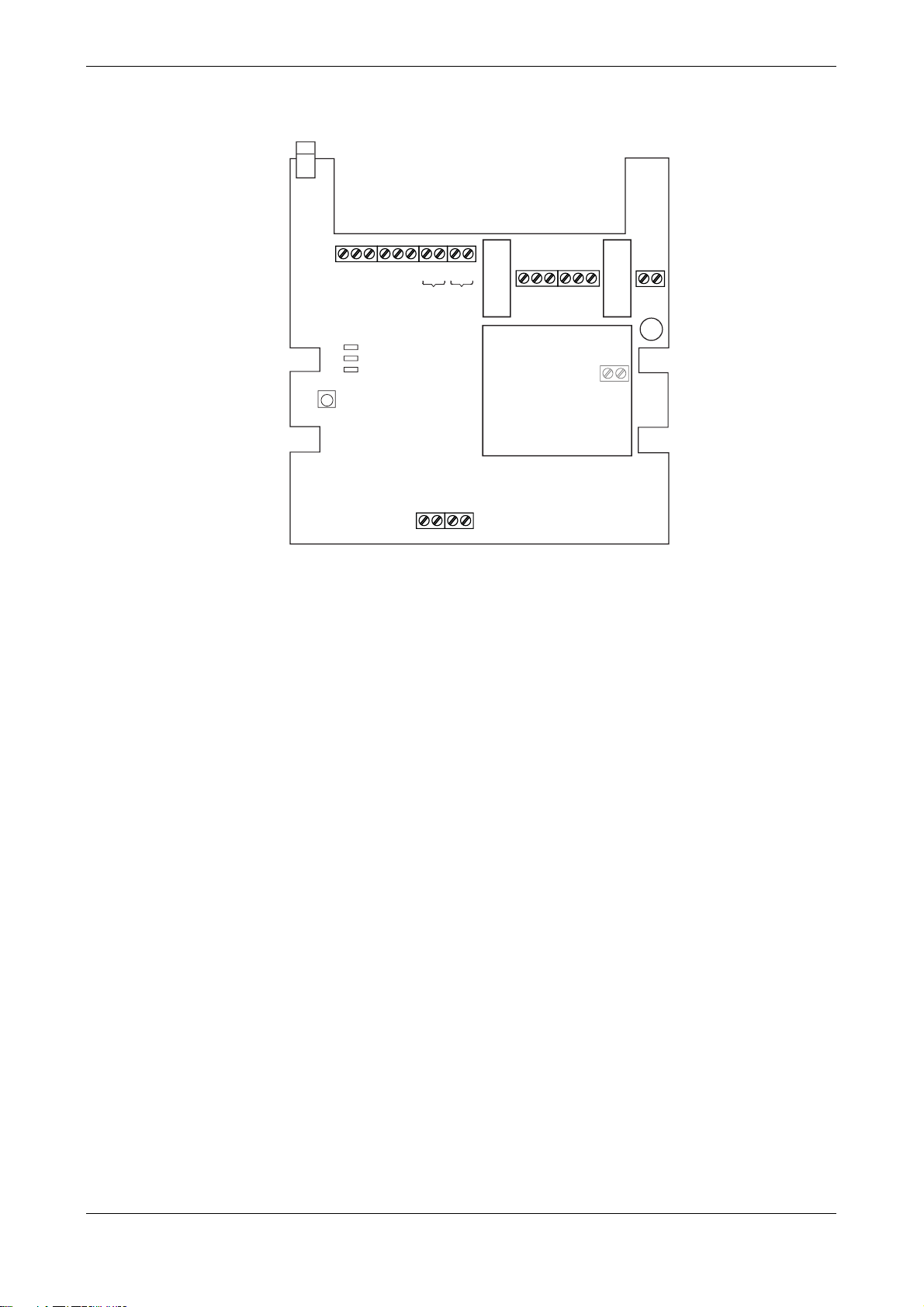
RY-FL Inputs / Outputs
2 Digital Inputs / 2 Analogue Inputs
2 0..10Vdc Outputs / 2 Relay Outputs
(individually configurable, total 4 IOs)
Register Parameter Description Modbus Function Code Data Type Range
10301 Device 1 Digital Input 1 (DI1) Status 02 - Read Discrete Inputs Bit On - Off
10401 Device 1 Digital Input 2 (DI2) Status 02 - Read Discrete Inputs Bit On - Off
30248 Device 1 Analogue Input 1 04 - Read Input Registers Signed 16 0..100%
30249 Device 1 Analogue Input 2 04 - Read Input Registers Signed 16 0..100%
1 Device 1 Digital Output 1 (DO1) - See Note 05 - Write Single Coil Bit0 On - Off
2 Device 1 Digital Output 2 (DO2) - See Note 05 - Write Single Coil Bit1 On - Off
40050 Device 1 Analogue Output 1 (AO1) - See Note 06 - Write Holding Registers Signed 16 0..100%
40051 Device 1 Analogue Output 2 (AO2) - See Note 06 - Write Holding Registers Signed 16 0..100%

SyxthSense Ltd
Copyright © 2009 SyxthSense Ltd. All rights reserved - 03/2009
PS SN1.125 - 3/5
Online store: www.syxthsense.com
Enquiries: T: 0870 20 80 100 F: 0870 20 80 200
RY-FL Wiring The diagram below illustrates the wiring details for the RY-FL device. Each RY-FL can be configured
to receive 2 input signals and control two output signals. The selection / configuration is done using
FLSER (ver 2.2 or later) service tool.
An example configuration (configurable via FLSER ver 2.2 or later):-
Input 1:Used as AI1 0..10Vdc to measure CO2 content
Input 2:Used as DI2 signal to monitor the window contacts
Output 1: Used as Relay 1 to drive the window open.
Output 2: Used as AO2 0..10Vdc control signal to drive a damper actuator.
NOTE: Both inputs and outputs are individually configurable for the required operation. Output
configuration is done automatically via Modbus messaging.
RY-FL Addressing Each wireless I/O-module, transmitter, repeater and F LTA control module/receiver (ver. 2.2 or later)
needs to have unique address. Wireless transmitter address consists of two parts; SID (Sensor ID)
and MID (Master ID). The I/O-module address is configured using FLSER service tool. MID is the
address of FLTA control module/receiver. Typically MID is set to one in a single FLTA network.
Example (single network, two devices):
Device 1: RY-FL IO-Module Address: SID (RYFL ID) = 1, MID = 1
Device 2: TEU-FL Address: SID = 2, MID =1
Master 1: FLTA Address: MID = 1
RY-FL and TEU-FL have MID address 1. This mens that they are transmitting
measurements/receiving output commands to FLTA that has been addressed with the same MID.
Example (two networks, two devices):
Device 1: RY-FL Address: SID (RYFL ID) = 1, MID =1
Device 2: RY-FL Address: SID (RYFL ID) = 1, MID =2
Master 1: FLTA Address: MID = 1
Master 2: FLTA Address: MID = 2
Device 1 transmits the measurements/receives commands to/from Master 1 (FLTA), and Device 2
transmits the measurements/receives commands to/from to Master 2. Although the both devices have
the same SID this will not cause problems as MID is different.
RF
ERROR
OK
CHANGE MID/SID
(SETTING ADDRESS)
RELAY 1 RELAY 2
NC NO C NC NO C
12345678 9
10
22 23 24 25
TRANSFORMER
RELAY 1
RELAY 2
RYFL
11 12 13 14 15 16 17 18
230VAC
NL
AO1
GND
24VAC
AO2
GND
24VAC
A1
B1
A2
B2
AI1 / DI1
AI2 / DI2
GND
GND
VALVE1 VA LVE2
3
0
3
1
2
4VA
C
(O
ption
)
G0
G

SyxthSense Ltd
Copyright © 2009 SyxthSense Ltd. All rights reserved - 03/2009
PS SN1.125 - 4/5
Online store: www.syxthsense.com
Enquiries: T: 0870 20 80 100 F: 0870 20 80 200
RY-FL Commissioning RY-FL input/output module operates at 868.30Mhz frequency providing wireless communication
module to automation systems. The device uses the latest RF technology for efficient data
transmission. Each RY-FL has two inputs that can be configured with the FLSER (ver 2.2 or later)
service to operate as a digital input or analogue 0..10Vdc input.
With RY-FL module controls also two outputs, that can be 0..10Vdc (and PWM) or 230Vac relay
outputs (individually configurable). RY-FL has two 0..10Vdc analogue outputs that operate in parallel
with 24Vac PWM outputs for thermic actuators.
RY-FL devices are configured using FLSER service tool (ver 2.2 or later) .
CONFIGURING RY-FL
1. Select MID position on the
FLSER service tool. Select using
+/- buttons the required Master ID
(MID 1..63).
Note: Typically the master ID is
set as 1 if only one wireless
TEFL/RY-FL network exists in the
building.
2. Please select S-RID on the
FLSER service tool switch.
3. Press M button on the FLSER service tool
once to display RYFL on the screen. This
screen is used to configure the RY-FL address
and the inputs of the RY-FL.
- Select RY-FL address by pressing + and -
buttons.
- Press OK to configure the first input
(DI1 = ON --> First wireless channel is configured to be used s digital input)
(DI1 = OFF --> First wireless channel is configured to be used as analogue output 0..10Vdc)
- Press OK to configure the second input as the first input.
- Finally press OK button after which the "WAIT" text starts to flash for 30 seconds on the FLSER
service tool. Bring the FLSER service tool close to the RY-FL.
4. The RY-FL is configured to the network by pressing the SETTING ADDRESS button on the printed
circuit board during the time when the FLSER flashed "WAIT". Once the RY-FL has been succesfully
addressed the LEDs on the RY-FL and FLSER flash in sequence for 5 times, and the FLSER display
shows OK. The RY-FL is now operational.
5. The FLSER service tool now shows the signal strength from the
RY-FL to the service tool and back. Signal strength RSSI 1-2 = low
signal quality, RSSI 3-5 = acceptable, RSSI 6-9 = good signal
strength. The large number illustrates the FLSER service tool signal
strength and the small number the RY-FL signal strength.
OFF
MID
S-RID
RSSI
REP
FLSER
OFF
MID
S-RID
RSSI
REP
OFF
MID
S-RID
RSSI
REP
FLSER
OFF
MID
S-RID
RSSI
REP
OFF
DI1=
DI1/AI1 input
selection:
[OFF=AI 0…10V
ON=0/1]
DI2/AI2 input
selection:
[OFF=AI 0…10V
ON=0/1]
OFF
DI2=
’OK’
’OK’
’OK’
1
RYFL
RYFL selection:
[1…99]
OFF
MID
S-RID
RSSI
REP
FLSER
RSSI 9

SyxthSense Ltd
Copyright © 2009 SyxthSense Ltd. All rights reserved - 03/2009
PS SN1.125 - 5/5
Online store: www.syxthsense.com
Enquiries: T: 0870 20 80 100 F: 0870 20 80 200
6. Finally switch the FLSER switch to OFF position. Now the RY-FL returns to normal mode and starts
to communicate to the FLTA receiver.
LED Operation RY-FL has three LED on its printed circuit board to indicate the operation of the device.
LED Description
RF Flashes when the device receives / transmits signals
ERROR On when the IO-module is in error.
OK ON when the module is in normal operation
Accessories Model Description
FLSER Wireless Service Tool for Addressing, Signal Strength Testing and
Repeater Emulation
FLTA Wireless Control Module / Receiver Unit with Modbus and 8
Analogue Outputs
FLAN Antennae for FLTA
FLREP Wireless Repeater to Extend Transmission Distance
FLREP-U Wireless Outdoor / High Power Repeater
This manual suits for next models
1
Popular Transmitter manuals by other brands

Lucoro Broadcast
Lucoro Broadcast FMTX100 user manual

Dwyer Instruments
Dwyer Instruments 608 Series Specifications-installation and operating instructions

Miccus
Miccus MHTXP-04 user manual

Conrad
Conrad FS20 S4UB operating instructions

Pyle
Pyle PLMP3C31B instruction manual

Kenco
Kenco KT Series Interface manual