Sony WRT-808A User manual

UHF SYNTHESIZED TRANSMITTER
WRT-808A
SERVICE MANUAL
U Model
1st Edition
Printed in Japan
Sony Corporation 1999. 7 11
Broadcasting & Professional Systems Company ©1999
WRT-808A (U) E
9-976-875-01

WRT-808A (U)
!WARNING
This manual is intended for qualified service personnel only.
To reduce the risk of electric shock, fire or injury, do not perform any servicing other than that
contained in the operating instructions unless you are qualified to do so. Refer all servicing to
qualified service personnel.
!WARNUNG
DieAnleitung ist nur für qualifiziertes Fachpersonal bestimmt.
Alle Wartungsarbeiten dürfen nur von qualifiziertem Fachpersonal ausgeführt werden. Um die
Gefahr eines elektrischen Schlages, Feuergefahr und Verletzungen zu vermeiden, sind bei
Wartungsarbeiten strikt die Angaben in der Anleitung zu befolgen. Andere als die angegeben
Wartungsarbeiten dürfen nur von Personen ausgeführt werden, die eine spezielle Befähigung
dazu besitzen.
!AVERTISSEMENT
Ce manual est destiné uniquement aux personnes compétentes en charge de l’entretien. Afin
de réduire les risques de décharge électrique, d’incendie ou de blessure n’effectuer que les
réparations indiquées dans le mode d’emploi à moins d’être qualifié pour en effectuer d’autres.
Pour toute réparation faire appel à une personne compétente uniquement.

1
WRT-808A(U)
Table of Contents
1. Operating Instructions
2. Service Overview
2-1. Disassembly ................................................................................................2-1
2-2. Note on Reassembly....................................................................................2-3
3. Electrical Alignment
3-1. Equipment and Tools ..................................................................................3-1
3-2. Adjustments.................................................................................................3-2
3-2-1. Power Supply Voltage Check ....................................................3-4
3-2-2. Carrier Frequency Adjustment ...................................................3-4
3-2-3. RF Power Output Adjustment ....................................................3-5
3-2-4. Reference Frequency Deviation Adjustment .............................3-6
3-2-5. Maximum Frequency Deviation Check .....................................3-7
3-2-6. Distortion Ratio Check...............................................................3-7
3-2-7. Input Level Control Check.........................................................3-8
3-2-8. AF/PEAK and POWER/BATT Indicators Check......................3-9
3-2-9. S/N Check ................................................................................3-10
3-2-10. Frequency Characteristics Check .............................................3-11
3-2-11. Tone Signal Adjustment...........................................................3-11
3-2-12. Battery Alarm Signal Check ....................................................3-13
3-2-13. Spurious Emissions Check.......................................................3-15
3-2-14. Occupied Band Width Check...................................................3-16
4. Semiconductor Pin Assignments
5. Spare Parts
5-1. Notes on Repair Parts..................................................................................5-1
5-2. Exploded Views ..........................................................................................5-2
5-3. Electrical Parts List .....................................................................................5-4
5-4. Accessories Supplied ..................................................................................5-7
6. Block Diagram
Overall Block Diagram ...............................................................................6-1

2WRT-808A(U)
7. Board Layouts and Schematic Diagrams
7-1. Board Layouts .............................................................................................7-1
AF-27 ........................................................................................................7-1
RF-90 ........................................................................................................7-1
7-2. Schematic Diagrams....................................................................................7-2
AF-27 ........................................................................................................7-2
RF-90 ........................................................................................................7-3

1-1
WRT-808A(U)
Section 1
Operating Instructions This section is extracted
from operation manual.
3-866-919-12 (1)
WRT-808A
UHF
Synthesized Transmitter
1999 by Sony Corporation [U64]
[U66]
[U68]
US
FR
ES
Operating Instructions
Mode d'emploi
Manual de instrucciones
Wireless Channel Lists / Listes des canaux sans fil /
Listas de canales inalámbricos
2US
Owner’s Record
The model and serial numbers are located at the rear of the
unit. Record the serial number in the space provided below.
Refer to these numbers whenever you call upon your Sony
dealer regarding this product.
Model No. WRT-808A Serial No.
Notice for customers in the U.S.A.
Use of Sony wireless devices is regulated by the Federal
Communications Commission as described in Part 74
subpart H of the FCC regulations and users authorized
thereby are required to obtain an appropriate licence.
You are cautioned that any changes or modifications not
expressly approved in this manual could void your authority
to operate this equipment.
Notice for customers in Canada:
Use of Sony wireless devices is regulated by the Industry
Canada as described in their Radio Standard Specification
RSS-123.
A licence is normally required. The local district office of
Industry Canada should therefore be contacted. When the
operation of the device is within the broadcast band, the
licence is issued on no-interference, no-protection basis with
respect to broadcast signals.
Operation of this device is subject to the following two
conditions: (1) this device may not cause interference, and
(2) this device must accept any interference, including
interference that may cause undesired operation of the
device.
Avis pour les clients au Canada:
L’usage des appareils sans-fil Sony est réglé par l’Industrie
Canada comme décrit dans leur Cahier des Normes
Radioélectriques CNR-123.
Une licence est normalement requise. Le bureau de
l’Industrie Canada doit être contacté. Lorsque l’opération de
l’appareil est dans les limites de la bande de radiodiffusion,
la licence est émanée sur la base de non-interférence, non-
protection avec les signaux de radiodiffusion.
L’utilisation de cet appareil est soumise aux deux conditions
suivantes : (1) cet appareil ne peut causer d’interférences, et
(2) cet appareil doit accepter toutes les interférences, y
compris les interférences capables de provoquer un
fonctionnement indésirable de l’appareil.
3
US
English Precautions
•
The unit is designed for use in ambient temperature range
of 0°C to 50°C (32°F to 122°F).
•
Do not place the unit on or near heat sources, such as
lighting equipment, power amplifiers, or in a place subject
to direct sunlight or excessive moisture. In such places,
the external finish or internal parts of the unit may be
damaged.
•
If the unit is used in a very humid or dusty place or in a
place subject to an active gas, clean its surface as well as
the connectors with a dry, soft cloth soon after use.
Lengthy use of the unit in such places or not cleaning it
after its use in such places may shorten its life.
•
When cleaning the unit, never use organic solvents such
as thinners or benzine, which will damage the finish of the
unit.
•
The unit has been factory adjusted precisely. Do not
tamper with its internal parts or attempt to repair it.
Table of Contents
Precautions ......................................................................... 3
Overview............................................................................. 4
Wireless Channels Selectable ........................................ 4
Features .......................................................................... 5
System Configuration .................................................... 6
Parts Identification ............................................................ 7
Power Supply ..................................................................... 8
Channel Setting.................................................................. 9
Microphone System Operation ...................................... 10
Specifications.................................................................... 12
Wireless Channel Lists.................................................. L-1
4US
U68 model
A 794-806 MHz frequency band is assigned to the WRT-
808A/68 model, permitting it to operate on any of 94 carrier
frequencies in 125-kHz steps of Sony original channel plan
in the range of TV channels 68 and 69.
For the selectable channels, see “Wireless Channel Lists” on
page L-1.
U66 model
A 782-794MHz frequency band is assigned to the WRT-
808A/66 model, permitting it to operate on any of 94 carrier
frequencies in 125-kHz steps of Sony original channel plan
in the range of TV channels 66 and 67.
For the selectable channels, see “Wireless Channel Lists” on
page L-2.
U64 model
A 770-782 MHz frequency band is assigned to the WRT-
808A/64 model, permitting it to operate on any of 94 carrier
frequencies in 125-kHz steps of Sony original channel plan
in the range of TV channels 64 and 65.
For the selectable channels, see “Wireless Channel Lists” on
page L-3.
Overview
The WRT-808A is a transmitter which converts a hand-held
dynamic microphone into a wireless microphone, ensuring
excellent sound quality of the microphone itself and
providing the convenience especially for Electronic News
Gathering (ENG), live and other Electronic Field Production
(EFP) applications. Combining with 800 MHz band Sony
UHF wireless microphone system, use this highly reliable
transmitter for broadcast and movie production purpose.
Wireless Channels Selectable
The transmitter and tuner of the wireless microphone system
are classified by frequency band.
A 12-MHz frequency band (or two consecutive-numbered
TV channels, such as 68 and 69 of the WRT-808A/68
model) is assigned to each transmitter and tuner model.
In building a UHF wireless microphone system, be sure to
combine a transmitter and a tuner having the same TV
channel number.

1-2 WRT-808A(U)
5US
Features
Easy selection of 94 channels
The PLL synthesized system assures easy selection of 94
channels and full compatibility with Sony 800 MHz series
wireless microphone system.
Easy and reliable connection
The WRT-808A can be adapted to a wide variety of wired
microphone which has a XLR audio connector. The reliable
connection assures the noise-free operation.
Compact and lightweight
High density mounting technology enables this compact and
light weight transmitter, to allow you to move anywhere for
Electronic News Gathering (ENG) and Electronic Field
Production (EFP).
Operation powered by easily available batteries
Approximately four hours of continuous operation is
ensured with two AA-size (LR6) alkaline batteries. By
virtue of DC-DC converter, consistent output power is
assured over the life of the batteries.
Battery status information on both transmitter and
tuner
To avoid the battery failure, the WRT-808A shows the
battery status with the LED indication in green, red and
flashing. About one hour before the battery exhausted, the
WRT-808A gives the battery information to make the alarm
on the tuner WRR-800A/801A/805A/850A.
LED indication of audio input
The AF/PEAK indicator allows you to comprehend the
condition of audio input level at a glance.
Continuous control of input attenuation
When an excessively strong audio signal is inputted, the
input level can be adjusted in the range of 0 to 50 dB
continuously.
When setting the 50 dB attenuation, the WRT-808A can
accept +4 dB (maximum 20 dB) line level input.
Selectable RF power output
You can select the RF output level either 50 mW or 10 mW
to suit the operating condition.
6US
System Configuration
Transmitter or microphone
WRT- Frequency band
808A TV channel Frequency (MHz)
U64 64 770.125 - 775.875
65 776.125 - 781.875
U66 66 782.125 - 787.875
67 788.125 - 793.875
U68 68 794.125 - 799.875
69 800.125 - 805.875
Model name
Overview
a) These models cover only 68 and 69 channels.
b) For these models, the AN-820A UHF antenna and the WD-820A UHF antenna divider are required.
Tuner
WRR-800A
WRR-801A
WRR-802A
WRR-805A
WRR-810A
WRR-820A
b)
WRR-840A
b)
WRR-850A
b)
WRR-855A
WRR-860A
a)
MB-806A
WRT-805A
WRT-807A
WRT-808A
WRT-810A
WRT-820A
WRT-822A
WRT-830A
a)
WRT-860A
WRT-867A
a)
The WRT-808A can be used with the WRR-800A/801A
UHF synthesized Diversity Tuner and also can be used with
the WRR-820A/840A/850A/855A UHF Synthesized
Diversity Tuner.
Sony 800 MHz band system models
8US
The transmitter can operate on two LR6 (size AA) alkaline
batteries continuously for about 4 hours at 25°C (77°F).
Installing the batteries
Power Supply
1
Turn the battery-compartment screw counterclockwise.
2
Match the polarities and insert the batteries.
3
Close the lid.
Battery indication
When you turn the power on, the POWER/BATT indicator
lights in green.
While in operation, the POWER/BATT indicator shows the
battery condition as shown below.
Lights in green: Good
Lights in red: The battery level is low. About one hour
is left for continuous operation.
Flashing in red: The batteries are almost exhausted.
The unit does not work.
Promptly replace the batteries when the POWER/BATT
indicator lights in red or flashes.
When the POWER/BATT indicator lights in red on this unit,
the BATT indication on the tuner (WRR-800A/801A/805A/
850A) starts flashing as a warning.
Note
The indication may be incorrect if the batteries are not new
when installed. If you plan to use the transmitter for a long
period, it is best to replace the batteries with new ones.
Two LR6 (size AA)
alkaline batteries
7US
3POWER/BATT indicator
4AF/PEAK indicator
5Input LEVEL control
6Channel select
switches 7RF power
output switch
1Microphone
connector
2POWER switch
Battery compartment
Microphone
release button
(under side of
the unit)
Parts Identification
1Microphone connector
Connect to a dynamic microphone which has a XLR type
connector.
2POWER switch
Turns the power of the transmitter ON or OFF.
3POWER/BATT indicator
When turning on the unit, the POWER/BATT indicator
lights in green. While in operation, the LED indicates the
battery condition.
See “Power Supply” on page 8.
4AF (audio frequency) /PEAK indicator
The AF/PEAK indicator lights in green when the supplied
audio frequency level is over the reference level. It lights in
red when the signal reaches the maximum level.
5Input LEVEL control
Controls the input attenuation level.
“–60” position provides 0 dB attenuation, and “–10”
position provides 50 dB attenuation.
6Channel select switches
Select the transmitting channel.
See “Channel Setting” on page 9.
7RF power output switch
In normal use, set the switch to “50”.
See “Use of RF power output switch” on page 11.

1-3
WRT-808A(U)
9US
Channel Setting
Caution
Turn off the transmitter when setting the transmitting
channel to eliminate interference or noise on other wireless
equipment.
Each
“Wireless Channel”
is represented on the unit by a 2-
digit TV channel number followed by another 2-digit
number, for example: 69-05.
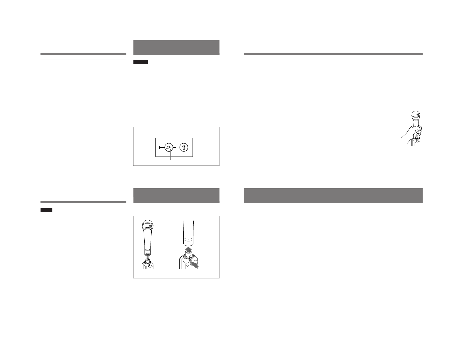
Set the channel select switches for the desired channel by
using a screw driver.
The left switch selects the TV band and the 10’s digit of the
transmitting channel. The right switch selects the 1’s digit of
the transmitting channel.
Example: when channel 69-05 is selected for U68 model
68
690
01
1
3
3
4
4
2
237
21
4
9
6
8
0
5
Set the left switch to “69” side “0”.
Set the right switch to “5” .
For the selectable wireless channels and frequencies, see
“Wireless Channel Lists” on pages L-1 to L-3.
Notes on batteries
•
Use new alkaline batteries, and check the recommended
“
useby” date on the bottom of the batteries.
•
Do not pair different types of batteries.
•
Always replace the two batteries together.
•
The batteries are not rechargeable.
•
Be careful to install the batteries with the correct polarity.
•
When not using the transmitter for a long period, remove
the batteries to avoid leakage. If the batteries do leak, clean
all leakage from the unit. Leakage left in the unit may cause
poor battery contact. If there seems to be poor battery
contact, consult your Sony dealer.
10US
Attach a
microphone
to the
microphone
connector.
To dettach a
microphone,
press the
microphone
release
button.
Notes
•
If the channel select switches are operated while the
transmitter is on, the POWER/BATT indicator flashes in
green as a warning.
•
If you set to any channel other than those listed in
“Wireless Channel Lists” on pages L-1 to L-3, the
POWER/BATT indicator flashes in green as a warning.
•
While the POWER/BATT indicator is flashing, the RF
output signal send from the transmitter becomes lower
than the usable level.
While POWER/BATT indicator on the transmitter is
flashing, the RF input indicator on the tuner may light, if
the transmitter locates near the tuner.
Though the RF input indicator lights on the tuner, the
Sony tuner (equipped with muting function) makes neither
noise nor audio output.
•
Make sure that the channel selected is the same as that
selected on the tuner used in the same system.
•
If there is a TV broadcasting station near by, do not use
the station's channel.
Microphone System
Operation
Channel setting
Microphone connection
If noise is heard
Depending on the environment where the system is
installed, outside noise or radio wave may disrupt the
transmission of certain channels.
To select a channel under this circumstance, turn off the
transmitter. Select a channel on the tuner, at which the RF
indicator is off. (A channel free from noise or radio wave
interference is selected.) Then, set the same channel on the
transmitter.
Sony microphones
F-780/740/730/720/
710, etc.
11US
Use of RF power output switch
The RF power output switch (located inside of the battery
compartment) selects the RF power output either 50 mW or
10 mW. In normal use, set the switch to “50” (factory preset
position).
50 mW output is suitable for optimum transmission over
long working distance.
10 mW output will be suitable for multi-channel operation
to eliminate the interference.
Use of input LEVEL control
When the AF/PEAK indicator lights in green continuously,
the supplied audio signal is continuously over the reference
level. If this occurs, use the input LEVEL control to avoid
sound distortion.
By turning the control to “–10”, the WRT-808A provides 50
dB input attenuation and can be inputted +4 dB (maximum
20 dB) line level signal.
Notes on microphone system operation
•
To operate with two or more channels, maintain a distance
of at least 30 cm (one ft.) between each pair of
transmitters.
For details of operation with two or more channels, refer
to the Operating Instructions for the WRR-800A/801A/
805A, etc.
•
Ensure that the transmitter set to channels not being used
are either turned off or set to the minimum output level.
•
When powering the transmitter on or off, to keep the noise
to a minimum, set the audio output level from the tuner or
mixer to a minimum.
•
Powering the transmitter on without checking the channel
selection first may interfere with the operation of other
microphones/transmitters, if the current setting is already
being used.
•
To prevent noise generation, keep the transmitters at least
3m (10 feet) away from the tuner antennas when the
system is operated using a group which allows selection of
up to 11 channels.
•
Do not grip the transmitter while using as it
will significantly degrade good
performance, causing dropouts, etc. Hold
the microphone itself as shown.
12US
Specifications
Transmitter and modulation section
Oscillator Crystal controlled PLL synthesizer
Carrier frequencies
U64 model: 770.125 to 781.875 MHz
(94 settings at 125 kHz
intervals)
U66 model: 782.125 to 793.875 MHz
(94 settings at 125 kHz
intervals)
U68 model: 794.125 to 805.875 MHz
(94 settings at 125 kHz intervals)
RF power output 50 mW/10 mW selectable
Frequency stability Within ±0.005%
Tone signal 32.768 kHz
Type of emission 110KF3E
Type of antenna Internal, 1/4- wave length wire
Pre-emphasis 50µs
Deviation ±5 kHz (–60 dBV
1)
, 1 kHz input,
with 0 dB audio attenuation)
Frequency response 70 to 15,000 Hz
Signal-to-noise ratio 57 dB or more
(A-weighted, with reference
deviation at WRR-800A/801A)
Audio attenuator 0 to 50 dB
Maximum input +26 dBV (1 kHz, with 50 dB audio
attenuation)
Power section
Power requirements 3.0 V DC
(two LR6/size AA alkaline
batteries)
Battery life Approx. 4 hours at 25° C (77° F)
with Sony LR6 alkaline batteries
General
Operating temperature 0° C to +50° C (32° F to 122° F)
Storage temperature –30° C to +60° C (–22° F to +140° F)
Dimensions 40 ×108 ×40 mm (w/h/d)
(1
5
/
8
×4
3
/
8
×1
5
/
8
inches)
Mass Approx. 175 g (6 oz) including
batteries
Supplied accessory
Operating Instructions (1)
Design and specifications are subject to change without
notice.
. . . . . . . . . . . . . . . . . . . . . . . . . . . . . . . . . . . . . . . . . . . . . . . . . . . . . . . . . . . . . . . . . . . . . . . . . . . . . . . . . . . . . . . . . . . . . . . . . . . . . . . . . . . . . . . . . . . . . . . . . . . . . . .
1) 0 dBV = 1 Vrms

1-4 WRT-808A(U)
L-1
Wireless Channel Lists / Listes des canaux sans fil /
Listas de canales inalámbricos
68-01 794.125 68-25 797.125 69-01 800.125 69-25 803.125
68-02 794.250 68-26 797.250 69-02 800.250 69-26 803.250
68-03 794.375 68-27 797.375 69-03 800.375 69-27 803.375
68-04 794.500 68-28 797.500 69-04 800.500 69-28 803.500
68-05 794.625 68-29 797.625 69-05 800.625 69-29 803.625
68-06 794.750 68-30 797.750 69-06 800.750 69-30 803.750
68-07 794.875 68-31 797.875 69-07 800.875 69-31 803.875
68-08 795.000 68-32 798.000 69-08 801.000 69-32 804.000
68-09 795.125 68-33 798.125 69-09 801.125 69-33 804.125
68-10 795.250 68-34 798.250 69-10 801.250 69-34 804.250
68-11 795.375 68-35 798.375 69-11 801.375 69-35 804.375
68-12 795.500 68-36 798.500 69-12 801.500 69-36 804.500
68-13 795.625 68-37 798.625 69-13 801.625 69-37 804.625
68-14 795.750 68-38 798.750 69-14 801.750 69-38 804.750
68-15 795.875 68-39 798.875 69-15 801.875 69-39 804.875
68-16 796.000 68-40 799.000 69-16 802.000 69-40 805.000
68-17 796.125 68-41 799.125 69-17 802.125 69-41 805.125
68-18 796.250 68-42 799.250 69-18 802.250 69-42 805.250
68-19 796.375 68-43 799.375 69-19 802.375 69-43 805.375
68-20 796.500 68-44 799.500 69-20 802.500 69-44 805.500
68-21 796.625 68-45 799.625 69-21 802.625 69-45 805.625
68-22 796.750 68-46 799.750 69-22 802.750 69-46 805.750
68-23 796.875 68-47 799.875 69-23 802.875 69-47 805.875
68-24 797.000 69-24 803.000
Channel Frequency(MHz) Channel Frequency(MHz) Channel Frequency(MHz) Channel Frequency(MHz)
Canal Fréquence Canal Fréquence Canal Fréquence Canal Fréquence
Frecuencia Frecuencia Frecuencia Frecuencia
For 68-Version Model Using TV Channels 68 and 69 /
Pour le modèle 68 utilisant les canaux de télévision 68 et 69 /
Para modelos de la versión 68 que utilizan los canales de TV 68 y 69
L-2
Wireless Channel Lists / Listes des canaux sans fil / Listas de canales inalámbricos
For 66-Version Model Using TV Channels 66 and 67 /
Pour le modèle 66 utilisant les canaux de télévision 66 et 67 /
Para modelos de la versión 66 que utilizan los canales de TV 66 y 67
66-01 782.125 66-25 785.125 67-01 788.125 67-25 791.125
66-02 782.250 66-26 785.250 67-02 788.250 67-26 791.250
66-03 782.375 66-27 785.375 67-03 788.375 67-27 791.375
66-04 782.500 66-28 785.500 67-04 788.500 67-28 791.500
66-05 782.625 66-29 785.625 67-05 788.625 67-29 791.625
66-06 782.750 66-30 785.750 67-06 788.750 67-30 791.750
66-07 782.875 66-31 785.875 67-07 788.875 67-31 791.875
66-08 783.000 66-32 786.000 67-08 789.000 67-32 792.000
66-09 783.125 66-33 786.125 67-09 789.125 67-33 792.125
66-10 783.250 66-34 786.250 67-10 789.250 67-34 792.250
66-11 783.375 66-35 786.375 67-11 789.375 67-35 792.375
66-12 783.500 66-36 786.500 67-12 789.500 67-36 792.500
66-13 783.625 66-37 786.625 67-13 789.625 67-37 792.625
66-14 783.750 66-38 786.750 67-14 789.750 67-38 792.750
66-15 783.875 66-39 786.875 67-15 789.875 67-39 792.875
66-16 784.000 66-40 787.000 67-16 790.000 67-40 793.000
66-17 784.125 66-41 787.125 67-17 790.125 67-41 793.125
66-18 784.250 66-42 787.250 67-18 790.250 67-42 793.250
66-19 784.375 66-43 787.375 67-19 790.375 67-43 793.375
66-20 784.500 66-44 787.500 67-20 790.500 67-44 793.500
66-21 784.625 66-45 787.625 67-21 790.625 67-45 793.625
66-22 784.750 66-46 787.750 67-22 790.750 67-46 793.750
66-23 784.875 66-47 787.875 67-23 790.875 67-47 793.875
66-24 785.000 67-24 791.000
Channel Frequency(MHz) Channel Frequency(MHz) Channel Frequency(MHz) Channel Frequency(MHz)
Canal Fréquence Canal Fréquence Canal Fréquence Canal Fréquence
Frecuencia Frecuencia Frecuencia Frecuencia
L-3
64-01 770.125 64-25 773.125 65-01 776.125 65-25 779.125
64-02 770.250 64-26 773.250 65-02 776.250 65-26 779.250
64-03 770.375 64-27 773.375 65-03 776.375 65-27 779.375
64-04 770.500 64-28 773.500 65-04 776.500 65-28 779.500
64-05 770.625 64-29 773.625 65-05 776.625 65-29 779.625
64-06 770.750 64-30 773.750 65-06 776.750 65-30 779.750
64-07 770.875 64-31 773.875 65-07 776.875 65-31 779.875
64-08 771.000 64-32 774.000 65-08 777.000 65-32 780.000
64-09 771.125 64-33 774.125 65-09 777.125 65-33 780.125
64-10 771.250 64-34 774.250 65-10 777.250 65-34 780.250
64-11 771.375 64-35 774.375 65-11 777.375 65-35 780.375
64-12 771.500 64-36 774.500 65-12 777.500 65-36 780.500
64-13 771.625 64-37 774.625 65-13 777.625 65-37 780.625
64-14 771.750 64-38 774.750 65-14 777.750 65-38 780.750
64-15 771.875 64-39 774.875 65-15 777.875 65-39 780.875
64-16 772.000 64-40 775.000 65-16 778.000 65-40 781.000
64-17 772.125 64-41 775.125 65-17 778.125 65-41 781.125
64-18 772.250 64-42 775.250 65-18 778.250 65-42 781.250
64-19 772.375 64-43 775.375 65-19 778.375 65-43 781.375
64-20 772.500 64-44 775.500 65-20 778.500 65-44 781.500
64-21 772.625 64-45 775.625 65-21 778.625 65-45 781.625
64-22 772.750 64-46 775.750 65-22 778.750 65-46 781.750
64-23 772.875 64-47 775.875 65-23 778.875 65-47 781.875
64-24 773.000 65-24 779.000
Channel Frequency(MHz) Channel Frequency(MHz) Channel Frequency(MHz) Channel Frequency(MHz)
Canal Fréquence Canal Fréquence Canal Fréquence Canal Fréquence
Frecuencia Frecuencia Frecuencia Frecuencia
For 64-Version Model Using TV Channels 64 and 65 /
Pour le modèle 64 utilisant les canaux de télévision 64 et 65 /
Para modelos de la versión 64 que utilizan los canales de TV 64 y 65

2-1
WRT-808A(U)
Section 2
Service Overview
2-1. Disassembly
Case (front), Battery lid assembly
Main frame assembly, Case (rear),
Battery spring assembly
Main frame assembly Battery spring assembly
AF-27 mounted PC board
Switching screw (case)
CN301
Case (rear) assembly
Case (rear)
Sheet (PWR)
P2 x 3.5
Switching screw (lid)
Battery lid assembly
Case (front)
Light guide plate
M1.7 x 8
M1.7 x 8
to page 2-2

2-2 WRT-808A(U)
CN102
Copper leaf sheet
Frame assembly Absorption sheet
Special flat screw 1.7 x 3
Special flat screw
1.7 x 3Special flat screw
1.7 x 3
RF-90 mounted PC board
AF-27 mounted PC board
CN103
Absorption sheet
B2 x 4Frame assembly
Connector assembly
Connector bracket
XLA 3P connector
Coil spring (ring)
Ring
*XLR 3P connector (male)
*Tool required
.XLR 3P connector (male)
(Sony Part No. : 1-563-030-21)
RF-90 mounted PC board,
AF-27 mounted PC board
Frame assembly, XLA 3P connector

2-3
WRT-808A(U)
2-2. Note on Reassembly
1. Connector Assembly
Frame assembly
Connector assembly
Connector assembly
*XLR 3P connector (male)
*
XLR 3P connector
(male)
*Tool required
.XLR 3P connector (male)
(Sony part No.: 1-563-030-21)
After attaching the connector assembly to the frame assembly,
detach the XLR 3P connector (male) from the connector assembly.
Attuch the XLR 3P connector (male),
securely to the connector assembly.
GRY
WHT
RED
BLK
XLA 3P connector
Connector bracket
Turn the harness
five turns.
Supplied with
XLA 3P connector.
2. Copper leaf sheet, Absorption sheet
3. LED (D502, D503)
Copper leaf sheet
Attuch the copper leaf sheet
as shown in the figwre.
Frame assembly
Align
Absorption sheet
Shield plate (A)
Shield plate (B) CP403
RF-90 board
AF-27 board
Frame assembly
SideView
RF-90 Board -B side-
D502
D503
5 mm 7 mm
5 mm
Cut.


3-1
WRT-808A (U)
3-1. Equipment and Tools
Equipment Required
Name Specifications Model Name
DC Power Supply Output regulated voltage: 0 to 5 V, 2 A _
DC Ammeter Measurement range: 300 mA _
Spectrum Analyzer Frequency: 10 kHz to 10 GHz ADVANTEST R3371B or equivalent
Modulation Analyze RF input Frequency: 150 kHz to 3 GHz ANRITSU MS616A or equivalent
RF Power Meter Range: 3 uW to 100 mW HEWLETT PACKARD 435B (with Power sensor HEWLETT
with Power sensor PACKARD 8482A) or equivalent
Audio Analyzer Oscillator: 20 Hz to 100 kHz HEWLETT PACKARD 8903B (with A-weight filter) or equivalent
Distortion meter
S/N meter
Level meter
Frequency Counter Frequency: 10 Hz to 1000 MHz HEWLETT PACKARD 5385A or equivalent
Effective digits: 10 digits
Resolution: 0.1 Hz
Oscilloscope Frequency: DC to 10 MHz _
Digital Volt Meter Effective digits: 31/ digits _
2
Tools Required
Name Part No. Remarks
MM-SMA (J) connector J-6402-480-A For RF signal output
SMA-BNC (J) connector J-6402-490-A For RF signal output
Adjustor (0.4 x1.3 mm) 7-721-052-81
Section 3
Electrical Alignment

3-2 WRT-808A (U)
3-2. Adjustments
This section describes the following adjustments and checks
required to satisfy specifications.
Adjustment and Check Items
3-2-1. Power Supply Voltage Check
3-2-2. Carrier Frequency Adjustment
3-2-3. RF Power Output Adjustment
3-2-4. Reference Frequency Deviation Adjustment
3-2-5. Maximum Frequency Deviation Check
3-2-6. Distortion Ratio Check
3-2-7. Input Level Control Check
3-2-8. AF/PEAK and POWER/BATT Indicator Check
3-2-9. S/N Check
3-2-10. Frequency Characteristics Check
3-2-11. Tone Signal Adjustment
3-2-12. Battery Alarm Signal Check
3-2-13. Spurious Emissions Check
3-2-14. Occupied Bandwidth Check
n
.0 dBV = 1 Vrms
.0 dBm = 0.775 Vrms
Preparation
1. When adjustments are performed, remove the Main frame
assembly (with battery terminal) from WRT-808A unit.
Refer to the “Section 2. Service Overview” for removal.
2. Peel off the copper leaf sheet from the main frame
assembly.
3.
Connect the MM-SMA (J) connector (J-6402-480-A)
with SMA-BNC (J) connector (J-6402-490-A) to the an-
tenna connector (CN402) on the RF-90 board as shown
below.
4. Unsolder the soldering bridge from the printed slit land
on the RF-90 board as shown below.
n
After completing adjustment and checking, be sure to
make a solder bridge to the slit land.
MM-SMA (J) connector
Battery terminal
Black
Red
CN402
SMA-BNC (J) connector
Main frame assembly
Copper leaf sheet
Unsolder the solder bridge.
After completing adjustment
and checking, be sure to
make a solder bridge.
n

3-3
WRT-808A (U)
Battery terminal
Red
DC ammeter
+–
Black
DC power supply
DC output
voltage: +3.0 ±0.1 V
+
+
–
–
5. Connecting the DC power supply.
Supply the DC power to the battery terminal springs as
shown below.
Check
After the DC power supply connection is completed, set
the power switch (S301) to ON, and check the level on
DC ammeter.
DC ammeter indication level: 160 to 200 mA
Adjustment Location
10 50
MIC input
(CN101)
AF/PEAK
(D503)
CN402
(RF output)
CT301
(carrier freq.)
RF-90 Board
S505S504RV101
(Input level control) (Channel select)
CT401
(RF power)
RV401
(RF power)
POWER/BATT
(D502)
TP201 RV201
(Tone signal)
RV202
(Ref. frequency dev.)
S401
(RF power output)
AF-27 BoardS301 (Power)

3-4 WRT-808A (U)
3-2-2. Carrier Frequency Adjustment
Equipment and Tools
DC power supply
DC output voltage: +3.0 ±0.1 V dc
DC ammeter
Frequency counter
Adjustor (Part No. 7-721-052-81)
MM-SMA (J) connector (Part No. J-6402-480-A)
SMA-BNC (J) connector (Part No. J-6402-490-A)
Connections
(For connecting the DC power supply, refer to the “Preparations”
on page 3-2.)
Switch and Control Setting
The following setting is to be perform with the channel se-
lect switches (S504 and S505).
Transmitting Channel setting:
U64 model: 65-01 channel (776.125 MHz)
U66 model: 67-01 channel (788.125 MHz)
U68 model: 69-01 channel (800.125 MHz)
Procedure
(1)
Connect the frequency counter to the antenna connector
(CN301) with MM-SMA (J) and SMA-BNC (J) connectors.
(2) Adjust 1CT301 so that the frequency counter reading
meets the following specification.
Specification:Carrier frequency mentioned in the table
below.
WRT-808A Carrier frequency
U64 model 776.125 MHz ±1 kHz
U66 model 788.125 MHz ±1 kHz
U68 model 800.125 MHz ±1 kHz
Adjustment: 1CT301/RF-90 Board (B side)
3-2-1. Power Supply Voltage Check
Equipment and Tools Required
DC power supply
DC output voltage: +3.0 ±0.1 V dc
DC ammeter
DC volt meter (or Digital multimeter)
Switch and Control Setting
The following setting is to be perform with the channel se-
lect switches (S504 and S505).
Transmitting Channel setting:
U64 model: 65-01 channel (776.125 MHz)
U66 model: 67-01 channel (788.125 MHz)
U68 model: 69-01 channel (800.125 MHz)
Procedure
(1) Set the POWER switch (S301) on the AF-27 board to
ON.
(2) Check the DC Voltage of the pin 3 or 4 of CN501 con-
nector on the RF-90 board to the specified voltage as
below:
Specification:DC Voltage at pin 3 or 4 of CN501
connector
= +5.0 ±0.1 V dc (For Vcc1)
DC voltmeter
RF-90 Board
Frame
(GND)
CN501 Pin3
Pin4
+
–
Frequency
counter
MM-SMA (J) connector
with SMA-BNC (J) connector
CT301
CN402

3-5
WRT-808A (U)
3-2-3. RF Power Output Adjustment
Equipment and Tools
DC power supply
DC output voltage: +3.0 ±0.1 V dc
DC ammeter
Power meter (with power sensor)
MM-SMA (J) connector (Part No. J-6402-480-A)
SMA-BNC (J) connector (Part No. J-6402-490-A)
Adjustor (Part No. 7-721-052-81)
Connections
(For connecting the DC power supply, refer to the “Preparations”
on page 3-2.)
Switch and Control Setting
The following setting is to be perform with the channel se-
lect switches (S504 and S505).
Transmitting Channel setting:
U64 model: 65-01 channel (776.125 MHz)
U66 model: 67-01 channel (788.125 MHz)
U68 model: 69-01 channel (800.125 MHz)
RF power output switch (S401): 50 mW
Input LEVEL control (RV101): “_60” (0 dB attenuation)
Turn the RV101 clockwise
fully.
Power meter
MM-SMA (J) connector
with SMA-BNC (J) connector
CT401
RV401
CN402
Power
sensor
Procedure
(1) Connect the power meter (with power sensor) to the an-
tenna connector (CN402)
with MM-SMA (J) and SMA-
BNC (J) connectors
.
(2) Adjust 1CT401 so that the power meter reading meets
the following specification.
Specification:Power meter reading = Maximum
Adjustment: 1CT401/RF-90 Board (B side)
(3) Adjust 1RV401 so that the power meter reading meets
the following specification.
Specification:
Power meter reading = 50
+15
mW
_10
Adjustment: 1RV401/RF-90 Board (B side)
(4) Set the RF output switch (S401) to the “10 mW” posi-
tion, and check that the power meter reading meets the
following specification.
Specification: Power meter reading = 11 ±5 mW

3-6 WRT-808A (U)
3-2-4. Reference Frequency Deviation
Adjustment
Equipment and Tools
DC power supply
DC output voltage: +3.0 ±0.1 Vdc
DC ammeter
Audio analyzer
Modulation analyzer
MEASUREMENT: FM
MEASUREMENT RANGE: AUTO or ±10 kHz
HPF: 50 Hz
LPF: 20 kHz or 15 kHz
DE EMPHASIS: 50 us
Adjustor (Part No. 7-721-052-81)
MM-SMA (J) connector (Part No. J-6402-480-A)
SMA-BNC (J) connector (Part No. J-6402-490-A)
Connections
(For connecting the DC power supply, refer to the “Preparations”
on page 3-2.)
Switch and Control Setting
The following setting is to be perform with the channel se-
lect switches (S504 and S505).
Transmitting Channel setting:
U64 model: 65-01 channel (776.125 MHz)
U66 model: 67-01 channel (788.125 MHz)
U68 model: 69-01 channel (800.125 MHz)
RF power output switch (S401): 50 mW
Input LEVEL control (RV101): “_60” (0 dB attenuation)
Turn the RV101 clockwise
fully.
Procedure
(1) Input 1 kHz, _60 dBV (_57.8 dBm) signal to the MIC
input connector (CN101).
(2) Adjust 1RV202 so that the frequency deviation for the
modulation analyzer reading meets the following speci-
fication.
Specification:Frequency deviation
= ±5 kHz ±0.1 kHz
Adjustment: 1RV202/AF-27 Board (B side)
(3) After the adjustment has been completed, perform the
“3-2-5. Maximum Frequency Deviation Check”.
Modulation
analyzer Oscilloscope
RF IN
AF OUT
MM-SMA (J) connector
with SMA-BNC (J) connector
CN402
MIC input
(CN101)
RF-90 Board
Audio analyzer
21
Oscillator
XLR 3Pin (male)
- wiring side -
3
Oscillator
Level meter
POWER/BATT (D502)
AF/PEAK (D503)

3-7
WRT-808A (U)
3-2-5. Maximum Frequency Deviation Check
n
Be sure to perform this adjustment after “3-2-4. Reference
Frequency Deviation Adjustment” has been completed.
Equipment and Tools
DC power supply
DC output voltage: +3.0 ±0.1 V dc
DC ammeter
Audio analyzer
Modulation analyzer
MEASUREMENT: FM
MEASUREMENT RANGE: AUTO or ±100 kHz
HPF: 50 Hz
LPF: 15 kHz or 20 kHz
DE EMPHASIS: 50 us
Oscilloscope
Adjustor (Part No. 7-721-052-81)
MM-SMA (J) connector (Part No. J-6402-480-A)
SMA-BNC (J) connector (Part No. J-6402-490-A)
Connections
Same as “3-2-4. Reference Frequency Division adjustments”.
Switch and Control Setting
The following setting is to be perform with the channel se-
lect switches (S504 and S505).
Transmitting Channel setting:
U64 model: 65-01 channel (776.125 MHz)
U66 model: 67-01 channel (788.125 MHz)
U68 model: 69-01 channel (800.125 MHz)
RF power output switch (S401): 50 mW
Input LEVEL control (RV101): “_60” (0 dB attenuation)
Turn the RV101 clockwise
fully.
Procedure
(1) Input 1 kHz, _24dBV (_21.8 dBm) signal to the MIC
input connector (CN101) with Mic input cable.
(2) Check that the frequency deviation for the modulation
analyzer reading meets the following specification.
Specification:Frequency deviation = ±40 kHz ±3 kHz
3-2-6. Distortion Ratio Check
Equipment and Tools
DC power supply
DC output voltage: +3.0 ±0.1 V dc
DC ammeter
Audio analyzer
Modulation analyzer
MEASUREMENT: FM
MEASUREMENT RANGE: AUTO or ±40 kHz
HPF: 50 Hz
LPF: 15 kHz or 20 kHz
DE EMPHASIS: 50 us
Oscilloscope
MM-SMA (J) connector (Part No. J-6402-480-A)
SMA-BNC (J) connector (Part No. J-6402-490-A)
Connections
(For connecting the DC power supply, refer to the “preparations”
on page 3-2.)
Modulation
analyzer Audio
analyzer
Distortion
mode
RF IN
AF OUT
MM-SMA (J) connector
with SMA-BNC (J)
connector
CN402
MIC input
(CN101)
Oscilloscope
RF-90 Board
Audio analyzer
21
Oscillator
Oscillator
XLR 3Pin (male)
- wiring side -
Level meter
3

3-8 WRT-808A (U)
3-2-7. Input Level Control Check
Equipment and Tools
DC power supply
DC output Voltage: +3.0 ±0.1 Vdc
DC ammeter
Audio analyzer
Modulation analyzer
MEASUREMENT: FM
MEASUREMENT RANGE: AUTO or ±40 kHz
HPF: 50 Hz
LPF: 15 kHz or 20 kHz
DE EMPHASIS: 50 us
Oscilloscope
MM-SMA (J) connector (Part No. J-6402-480-A)
SMA-BNC (J) connector (Part No. J-6402-490-A)
Connections
Same as “3-2-6. Distortion Ratio Check”.
Switch and Control Setting
The following setting is to be perform with the channel
select switches (S504 and S505).
Transmitting Channel setting:
U64 model: 65-01 channel (776.125 MHz)
U66 model: 67-01 channel (788.125 MHz)
U68 model: 69-01 channel (800.125 MHz)
RF power output switch (S401): 50 mW
Input LEVEL control (RV101):
“_60”(0 dB attenuation) Turn the RV101 clockwise fully.
Procedure
(1) Connect the audio analyzer (level meter) to the AF OUT
connector on the modulation analyzer.
(2) Set the audio analyzer to level meter mode.
(3) Input 1 kHz, _60 dBV (_57.8 dBm) signal to the MIC
input connector (CN101) from audio analyzer (oscilla-
tor).
(4) Reads the indication on the audio analyzer (level meter).
(5) Set the SENSITIVITY on the audio analyzer (level
meter) so that the audio analyzer (level meter) reads 0
dB.
(6) Turn the RV101 (Input LEVEL control) counterclock-
wise fully.
(7) Check that audio analyzer (level meter) reading is _26
dB. (Indication level is _26 dB as compared with
the read level of procedure (5) above.)
+2
_1+2
_1
Switch and Control Setting
The following setting is to be perform with the channel se-
lect switches (S504 and S505).
Transmitting Channel setting:
U64 model: 65-01 channel (776.125 MHz)
U66 model: 67-01 channel (788.125 MHz)
U68 model: 69-01 channel (800.125 MHz)
RF power output switch (S401): 50 mW
Input LEVEL control (RV101): “_60” (0 dB attenuation)
Turn the RV101 clockwise
fully.
Procedure
(1) Connect the audio analyzer (distortion analyzer) to the
AF OUT connector on the modulation analyzer.
(2) Set the audio analyzer to distortion measurement (dis-
tortion mode).
(3) Input 1 kHz, _60 dBV (_57.8 dBm) signal to the MIC
input connector (CN101) from audio analyzer (oscilla-
tor).
(4) Check that the distortion analyzer reading is less than
0.90 %.
(5) Input 1 kHz, _24 dBV (_21.8 dBm) signal to the MIC
input connector (CN101).
(6) Check that the distortion analyzer reading is less than
0.9 %.
Other manuals for WRT-808A
3
Table of contents
Other Sony Transmitter manuals

Sony
Sony STWA-C101 User manual

Sony
Sony WRT-808A User manual

Sony
Sony RSE-500 User manual

Sony
Sony 3-873-945-12 (1) User manual

Sony
Sony TMR-BT8iP - Bluetooth Wireless Transmitter Installation and operating instructions

Sony
Sony WLA-NS7 User manual

Sony
Sony WRT-8B User manual

Sony
Sony AIR-SA17Ti User manual

Sony
Sony DWT-B01N User manual

Sony
Sony TMR-RF950R User manual