Bravo Synergic MIG 4540/T User manual

CEBORA S.p.A. 1
BRAVO SYNERGIC
POWER SOURCE art. 597
SERVICE MANUAL
3.302.200 29/04/05

CEBORA S.p.A. 2
CONTENTS
1 - GENERAL INFORMATION...........................................................................................................3
1.1 - Introduction....................................................................................................................................3
1.2 - General service policy....................................................................................................................3
1.3 - Safety information..........................................................................................................................3
1.4 - Electromagnetic compatibility.......................................................................................................3
2 - SYSTEM DESCRIPTION................................................................................................................4
2.1 - Introduction....................................................................................................................................4
2.2 - Technical specifications.................................................................................................................4
2.3 - Description of power source. .........................................................................................................4
3 - MAINTENANCE.............................................................................................................................6
3.1 - Periodic inspection, cleaning. ........................................................................................................6
3.2 - Operating sequence........................................................................................................................6
3.2.1 - Power source commands and connections. .................................................................................6
3.2.2 - Power source operation. ..............................................................................................................7
3.3 - Troubleshooting. ............................................................................................................................9
3.3.1 - The power source does not start, control panel off......................................................................9
3.3.2 - Power source powered, control panel on, fan (58) does not work.............................................10
3.3.3 - Control panel on, display and signals do not show correct values............................................11
3.3.4 - The start button produces no effect. ..........................................................................................12
3.3.5 - System powered, no gas flows from the torch...........................................................................12
3.3.6 - Power source powered, the wire feeder motor does not work...................................................13
3.3.7 - In open circuit operation, the output voltage is not regular.......................................................14
3.3.8 - In resistive load operation, the output voltage is not regular.....................................................16
3.3.9 - In synergic mode, he welding quality is not satisfactory, the wire speed is not suited to the
output current. ...........................................................................................................................17
3.3.10- Arc difficult to strike, the arc goes out immediately after lighting............................................17
3.3.11- When start button is released, the wire sticks to the workpiece (ineffective motor braking)....18
3.4 - Alarm signals. ..............................................................................................................................19
3.4.1 - Led (F) lit = transformer (5) temperature too high, or wire coil cover open, or cooling liquid
flow low, or fuse on 16 Vac power supply tripped. ..................................................................19
4 - COMPONENTS LIST....................................................................................................................20
4.1 - Power source art. 597 : see file ESP597.pdf enclosed at the end of the manual..........................20
4.2 - Components table : see file ESP597.pdf enclosed at the end of the manual................................20
4.3 - Spare parts list..............................................................................................................................20
4.4 - Fuse table. ....................................................................................................................................20
5 - ELECTRICAL DIAGRAMS..........................................................................................................21
5.1 - Power source art. 597 : see file SCHE597.pdf enclosed at the end of manual. ...........................21
5.2 - Waveforms...................................................................................................................................21
5.2.1 - Wire feeder motor (403) voltage during correct braking (par. 3.3.11)......................................21
5.2.2 - Wire feeder motor (403) voltage during incorrect braking (par. 3.3.11)...................................21
5.3 - Timing board (62) code 5.602.211...............................................................................................22
5.4 - Control board (4) code 5.602.205................................................................................................23
3.302.200 29/04/05

CEBORA S.p.A. 3
1- GENERAL INFORMATION
1.1 - Introduction.
The purpose of this manual is to train personnel assigned to carry out maintenance of the
power source art. 597 for MIG Synergic welding system.
1.2 - General service policy.
It is the responsibility of the customer and/or operator to use the equipment appropriately, in
accordance with the instructions in the Manual, as well as to maintain the equipment and related
accessories in good working condition, in compliance with the instructions provided in the
Service Manual.
Any internal inspection or repairs must be carried out by qualified personnel who are
responsible for any intervention on the equipment.
It is forbidden to attempt to repair damaged electronic boards or modules; replace them with
original Cebora spare parts.
1.3 - Safety information.
The safety notes provided in this manual are an integral part of those given in the Instruction
Manual. Therefore, before working on the machine, please read the paragraph on safety
instructions in the aforementioned manual.
Always disconnect the power cord from the mains before accessing the interior of the
equipment.
Some internal parts, such as terminals and dissipaters, may be connected to mains or
otherwise hazardous potentials. It is therefore forbidden to work with the safety guards removed
from the machine unless strictly necessary. In this case, take special precautions such as wearing
insulating gloves and footwear, and working in a perfectly dry environment with dry clothing.
1.4 - Electromagnetic compatibility.
Please read and observe the instructions provided in the paragraph “Electromagnetic
compatibility” of the Instruction Manual.
3.302.200 29/04/05

CEBORA S.p.A. 4
2- SYSTEM DESCRIPTION
2.1 - Introduction.
The BRAVO SYNERGIC MIG 4540/T is a system for welding mild and stainless steel and
aluminium, using a Synergic MIG process.
It is made up of an electrical power source (art. 597) with on board wire feeder unit and a
range of accessories to adapt to various types of use (see list in the Sales Catalogue).
The power source is controlled by a microprocessor circuit, which manages the operative
functions of the welding system and operator interface.
2.2 - Technical specifications.
To verify the technical specifications, see the machine plate, Instruction Manual, and Sales
Catalogue.
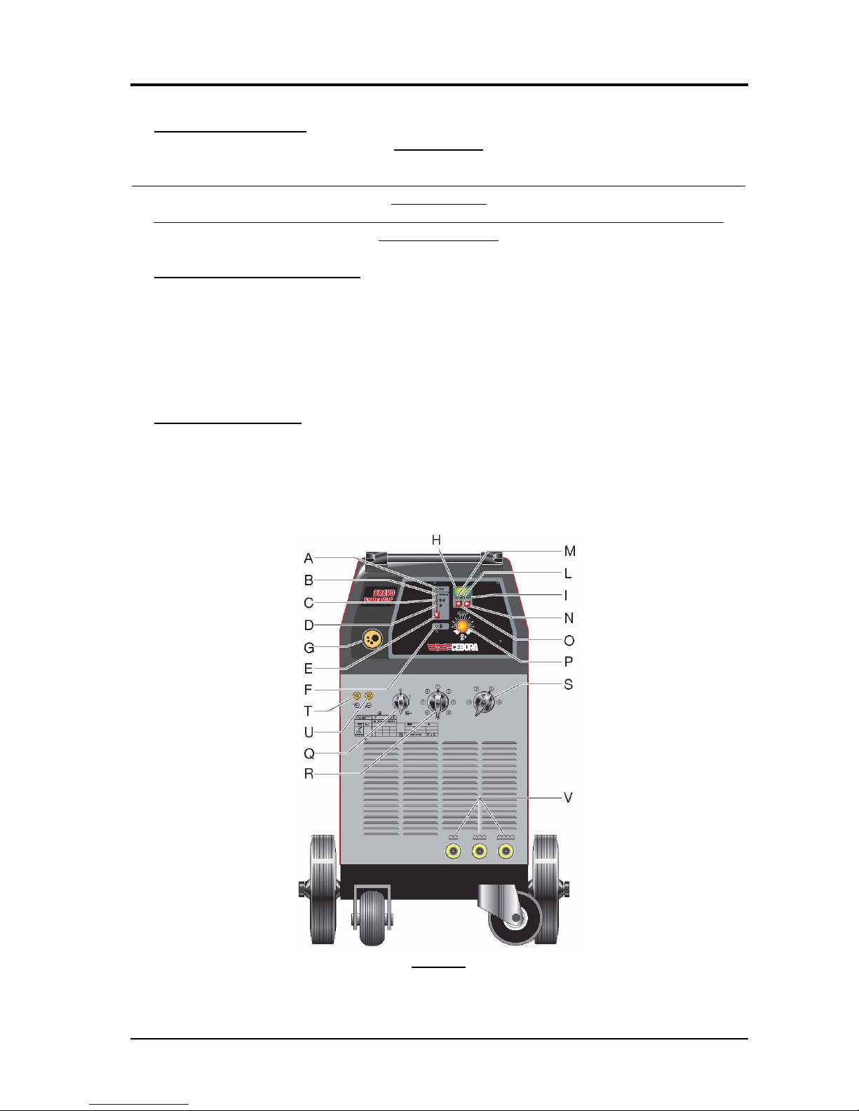
2.3 - Description of power source.
Art. 597 is a direct current power source, essentially electromechanical, consisting of a three-
phase transformer and a rectifier bridge.
Referring to the electrical diagram in par. 5, the fig. in par. 4 and fig. 3.2.1 you can see the
main blocks that make up the power source.
The switch (Q)(43) powers the service transformer (55), that supplies power to the fan (58),
timing board (62), socket (15) for the cooling unit, and control board (4).
The switches (R)(44) and (S)(45) act as selectors for the output voltage of the power source.
Depending on their position, the supply voltage is applied to the various intermediate sockets of
the primary winding of the transformer (5), for the purpose of altering the voltage on the
secondary winding and thus at the power source output. This adapts the output current of the
power source to specific welding needs.
The mains voltage is applied to the power transformer (5) only after the contactor (51) closes,
which is controlled by the control board (4), based on the welding conditions set by the operator.
The service transformer (55) receives the supply voltage through the voltage change terminal
board (59), which serves to adapt power source operation to the mains voltage (230 or 400 Vac).
As a result of this adaptation, and operation as an autotransformer of the primary winding of
the service transformer (55), fan (58) and cooling unit, if connected to socket (15), they are
always powered at 230 Vac even with the mains at 400 Vac; the secondary voltages of the
service transformer (55) also maintain the same value.
The 28 Vac secondary voltage powers the control board (4).
The 16 Vac secondary voltage powers the timing board (62), which manages the pump and
fan on the cooling unit through the socket (15), the fan (58) of the power source, and the circuit
corresponding to the safety devices of the welding system (microswitch (46) on the guard of the
wire feed unit, thermostat on the windings of power transformer (5) and flow meter on the
cooling unit). If the cooling unit is not present the plug (16), provided, must be connected to the
connector (17).
When one of the these devices is tripped, it in turn trips the alarm of the control board (4) that
stops the power source by opening the contactor (51); the alarm is indicated on the control panel
(led F lit).
The control board (4) contains a microprocessor circuit that manages all of the power source
functions, the operator interface and the wire feeder motor speed control, in compliance with the
synergic programs saved on the board.
The control board (4) receives the positioning information from the switches (44) and (45),
corresponding to the output power source voltage selection, and consequently adjusts the motor
3.302.200 29/04/05

CEBORA S.p.A. 5
speed based on the most suitable synergic curve selected from among those saved in the memory
of the board.
Within the speed range associated with the selected synergic curve, it is possible to fine-tune
the wire speed using the potentiometer provided (knob P).
If the manual program is set (P00 on display (H)) the wire speed is adjusted manually, thus
regardless of the position of switches (44) and (45), and may be adjusted from 0 to
approximately 20 m/min. using knob (P).
The motor speed is adjusted by the electronic regulator present on the control board (4),
which is powered with the same supply voltage as the control board (4), supplied by the service
transformer (55).
When the torch button is pressed, the control board (4) sends the closing command to the
contactor (51), which coincides with the start signal for the timing board (62), which controls
operation of the fan (58) and the cooling unit. After welding, thus when the start button on the
torch is released, the contactor (51) is disabled immediately, while the pump and fans on the
cooling unit and fan (58) on the power source remain running for approximately ten minutes
longer, after which time they also stop and await a new start command.
The secondary transformer (5) circuit is connected to the rectifier bridge (56), which keeps the
welding current constant. The choke (53) inserted downstream of the rectifier bridge (56), serves
to level the welding current, and its intermediate sockets allow you to maximize welding quality
as the material to be welded changes.
The shunt (23) inserted between the positive pole of the rectifier bridge (56) and the central
adapter (39) of the torch, provides the control board (4) with the signal to show the welding
current on display (H) during welding.
The power source power outputs are gathered together on the front panel. A central adapter
(G)(39) is set up for the torch with a built-in power socket, two contacts for the start command,
and a pneumatic socket for gas.
The negative output terminal (V) of the power source is located on the front panel, and is
composed by three terminals of the choke (53) to select the choke portion to use.
The following are present on the rear panel of the power source:
−the socket (15) for the cooling unit power supply;
−the connector (17) to connect the flow meter on the cooling unit;
The gas solenoid valve (12) is activated by the torch start button, and its opening time also
depends on the post-gas time set.
Similarly the line contactor (51) is activated by the torch start button, and its closing time also
depends on the Burn-Back time set and the status of the safety parts in the power source (safety
switch (46) on the wire feed unit guard, and thermostat located on the windings of the power
transformer (5)).
The signals processed by the electronic boards and present at their connectors are listed in the
table in chapter five of this manual.
3.302.200 29/04/05
CEBORA S.p.A. 6
3- MAINTENANCE WARNINGS
ANY INTERNAL INSPECTIONS OR REPAIRS MUST BE CARRIED OUT BY QUALIFIED
PERSONNEL.
DISCONNECT THE POWER SOURCE FROM THE MAINS BEFORE PERFORMING
MAINTENANCE.
3.1 - Periodic inspection, cleaning.
Periodically remove dirt and dust from the internal parts of the power source, using a jet of
low-pressure dry compressed air or a brush.
Check the condition of the output terminals and power cables of the power source and torch;
replace if aged or damaged.
Check the condition of the internal power connections and connectors on the electronic
boards; if you find “loose” connections, tighten or replace the connectors.
3.2 - Operating sequence.
The following sequence shows the correct operation of the machine. It may be used as a
guiding procedure for troubleshooting.
It must be carried out after each repair without any errors.
3.2.1 - Power source commands and connections.
NOTES
Operations preceded by this symbol refer to operator actions.
♦Operations preceded by this symbol refer to machine responses that must occur following an
operator action.
3.302.200 29/04/05

CEBORA S.p.A. 7
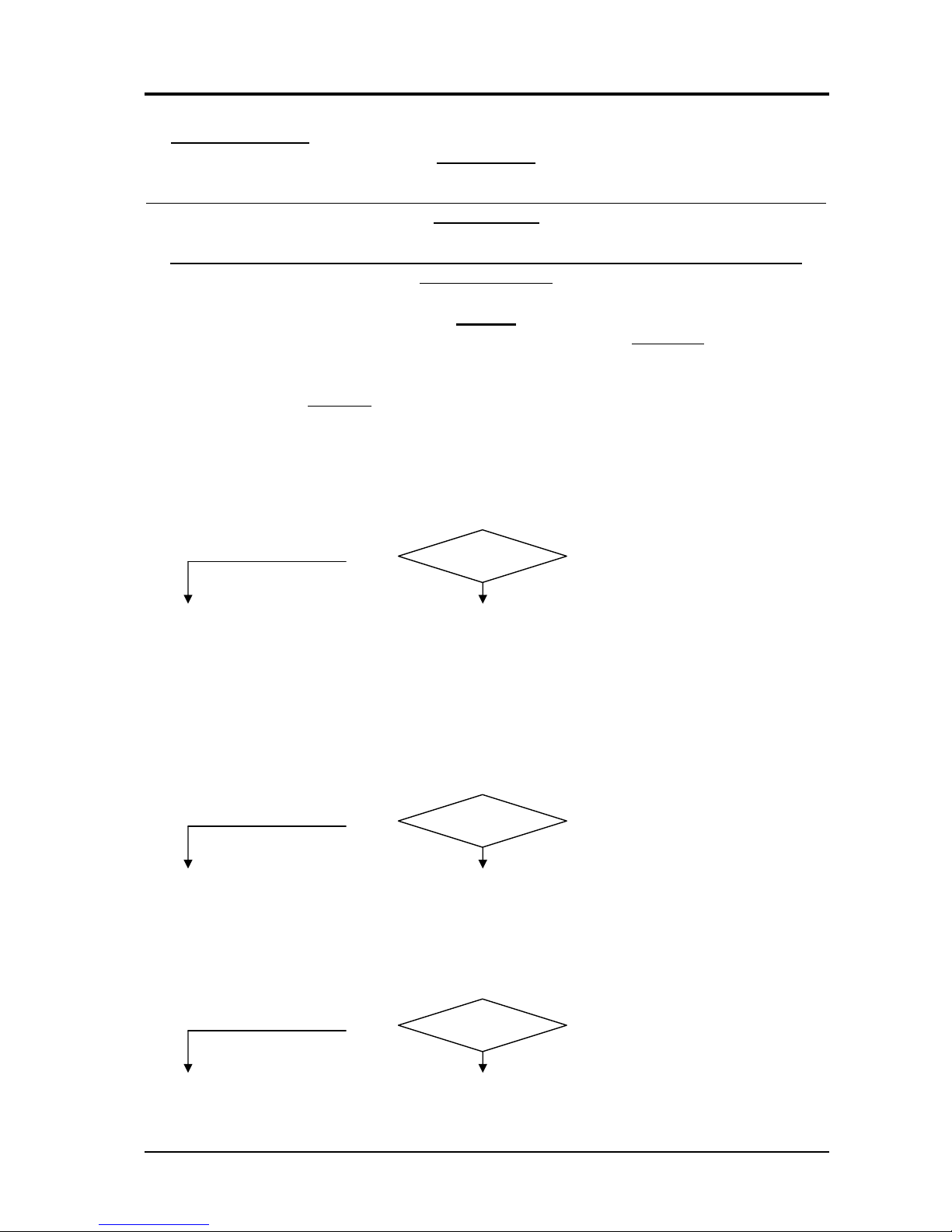
3.2.2 - Power source operation.
System shut off and disconnected from the mains.
Connect the gas supply to the fitting provided on the rear panel.
Insert the plug (16), provided, into connector (17) of the power source.
Connect the torch to the central adapter (G) of the power source.
Connect the negative pole (V) cable of the power source to the workpiece.
Connect the power source to the mains.
Set the switch (Q) on the power source to position 1.
♦System powered, on control panel all leds and displays are lit (lamp-test).
♦After one second, display (H) shows the version of the work programs saved
(ex:F01).
♦After two seconds, display (H) shows the selected working program, and some
indicator leds remain lit; all as they were set before the last time the unit was shut
off.
Correct?
♦After two seconds, display (H) shows the wire speed programmed for the manual
program, or, for synergic programs, the programmed current based on the position
of switches (44) and (45) and knob (P).
NO (see 3.3.1, 3.3.3).
YES
Press the key (E) several times to select the “Mode” repeatedly in sequence.
Correct?
♦Each time the key (E) is pressed, the leds (B), (C), and (D) light in sequence, and
display (H) shows the value of the function indicated by the corresponding lit led.
NO (see 3.3.3).
YES
WARNING
DURING THE FOLLOWING TESTS DO NOT AIM THE TORCH AT PEOPLE OR PARTS
OF THE BODY, BUT ONLY TOWARDS AN OPEN SPACE OR THE WORKPIECE.
Switch the switches (44) and (45) for an output voltage suited to the welding to be done.
Use the key (E) to select the “program” mode, led (B) lit.
Use the button (O) or (N) to select the manual working program (P00 on display (H)).
Turn knob (P) for a wire speed suitable for the set welding current.
Hold down the torch start button for a few seconds.
♦Gas begins to flow from the torch as long as the button is held down plus the set
post-gas time.
♦Wire begins flowing out of the torch, or in any case the wire feeder motor begins
operating, and open-circuit output voltage is generated for as long as the button is
held down.
Correct?
♦Fan (58) running for as long as the button is held down plus the time set on timing
board (62) (approximately 10 minutes).
NO (see 3.3.2, 3.3.4, 3.3.5.
3.3.6, 3.3.7).
YES
Move the torch near the workpiece and press the torch trigger.
♦Begin welding. Turn knob (P) to the current level and wire speed suitable for the
kind of welding to be performed.
3.302.200 29/04/05
CEBORA S.p.A. 8
Correct?
♦Display (H) shows the welding current.
NO (see 3.3.8, 3.3.10).
YES
Release the start button, holding the torch in welding position until gas stops flowing out.
Correct?
♦The arc shuts down immediately without the wire sticking to the workpiece, the
wire stops exiting the torch, and gas flow is interrupted after the post-gas time set.
NO (see 3.3.11).
YES
Use the keys (E), (O) or (N) to select a saved synergic program (see Instruction Manual and
table provided in the compartment of the wire feed unit).
♦Display (H) indicates the selected program number (ex.: P01).
♦After 1 second display (H) shows the programmed value of the measurement
indicated by lighting one of the leds (M), (L) or (I). This value may be selected
using the keys (O) and (N).
♦With current selected (led M lit) the value on display (H) may be changed using
knob (P) and switches (44) and (45).
Correct?
♦With voltage (led I lit) or thickness (led L lit) selected, the value on display (H)
may be changed using the switches (44) and (45).
NO (see 3.3.3, 3.3.7).
YES
Use the keys (E), (O) or (N) to select a synergic program suitable for the type of welding to be
done (see Instruction Manual and table provided in the compartment of the wire feed unit).
Turn the knob (P) to the central position (SYNERGIC).
Move the torch near the workpiece and press the start button.
Correct?
♦Begin welding. Turn the knob (P) for fine-tune the wire speed within the field
permitted by the synergic curve being used. Changing the speed also affects the
welding current shown on display (H) and thus the quality of the welding in
progress.
NO (see 3.3.9, 3.3.10).
YES
Release the start button, holding the torch in welding position until gas stops flowing out.
Correct?
♦The arc shuts down immediately without the wire sticking to the workpiece, the
wire stops exiting the torch, and gas flow is interrupted after the post-gas time set.
NO (see 3.3.11).
YES
REGULAR OPERATION.
3.302.200 29/04/05
CEBORA S.p.A. 9
3.3 - Troubleshooting. WARNINGS
ANY INTERNAL INSPECTIONS OR REPAIRS MUST BE CARRIED OUT BY QUALIFIED
PERSONNEL.
DISCONNECT THE POWER SOURCE FROM THE MAINS BEFORE PERFORMING
MAINTENANCE.
NOTES
Items in boldface describe problems that may occur on the machine (symptoms).
Operations preceded by this symbol refer to situations the operator must determine (causes).
♦Operations preceded by this symbol refer to actions the operator must perform in order to
solve the problems (solutions).
3.3.1 - The power source does not start, control panel off.
MAINS SUITABILITY TEST.
Correct?
Missing voltage at the power source input due to tripped mains protection.
NO
YES
♦Eliminate any short-circuits or isolation leaks between the various conductors and
towards earth in connections between the power cable, terminal board (50),
contactor (51), switches (44) (45), service transformer (55), fan (58) and socket
(15).
♦Mains not suitable to power the power source (ex.: insufficient installed power).
MAINS CONNECTION TEST.
Correct?
Contactor (51), power terminals = approximately 3 x 400 Vac or 3 x 230 Vac, depending on
mains voltage.
YES
NO
♦Check power cable and plug and connections on terminal board (50), and replace
if necessary.
♦Check the mains voltage conditions.
CONTROL BOARD (4) POWER SUPPLY TEST.
Correct?
Control board (4), connector J7, terminals 1 - 2 = approximately 28 Vac.
YES
NO
♦Check the wiring between service transformer (55), and control board (4).
♦Check the wiring between contactor (51), switch (43), voltage change terminal
board (59), service transformer (55), fan (58) and socket (15).
3.302.200 29/04/05
CEBORA S.p.A. 10
♦Make sure the setting of the voltage change terminal board (59) matches the
mains voltage.
♦Make sure the fuse on the primary circuit of the service transformer (55) is intact.
If interrupted, replace and check the resistance of the primary winding.
Correct values: terminals 0 – 230V = approximately 7 ohm;
terminals 0 – 440V = approximately 12 ohm.
If incorrect replace the service transformer (55).
♦Make sure the fuse on the 28Vac secondary circuit of the service transformer (55)
is intact. If interrupted, replace it and check the resistance on terminals 1 and 2 of
J7 on control board (4). Correct value = >Mohm in both measurement directions.
If incorrect, replace control board (4).
♦Replace service transformer (55).
♦Replace control board (4).
3.3.2 - Power source powered, control panel on, fan (58) does not work.
NOTE
The fan (58) may be activated using the start command of the torch button, and continues
running after it is released for the time set on the timing board (62)(approximately 10 minutes).
FAN (58) TEST.
Correct?
Terminals of fan (58) = approximately 230 Vac, with mains at either 230 Vac or 400 Vac with
start button pressed.
NO
YES
♦Make sure that there are no mechanical impediments blocking the fan.
♦Check, with power source off, the resistance on fan (58) terminals. Correct value
= approximately 50 ohm. If >Mohm (winding broken), replace the fan (58).
♦Replace the fan (58).
♦Check the wiring between fan (58), terminal board on service transformer (55) and timing
board (62)(contact of RL1).
♦Make sure the fuse on the power supply for fan (58) is intact, located on the terminal board of
the service transformer (55). If interrupted, before replacing it check the resistance between
the terminals of the fan (58). Correct values = approximately 50 ohm.
If incorrect, replace fan (58).
♦Make sure the contactor (51) remains closed for as long as the start button is held down. If
incorrect carry out the START COMMAND TEST in par. 3.3.4. If correct check on terminals
7 and 8 of J1 timing board (62) voltage = approximately 28 Vac when contactor (51) is
closed. If incorrect check the wiring between timing board (62) and contactor (51).
TIMING BOARD (62) POWER SUPPLY TEST.
Timing board (62), connector J1, terminals 1 and 2 = approximately 16 Vac.
3.302.200 29/04/05

CEBORA S.p.A. 11
Correct?
YES
NO
♦Check the wiring between the 16 Vac winding of the service transformer (55) and
J1 on timing board (62).
♦Make sure the fuse on the 16V secondary circuit of the service transformer (55) is
intact. If interrupted, before replacing it check the resistance on terminals 1 and 2
of J1 on timing board (62), in the following conditions:
−With plug (16) removed from connector (17) on the power source: Correct
value = >Mohm in both measurement directions. If incorrect replace the timing
board (62).
−With plug (16) inserted in connector (17) on the power source: Correct values
= from approximately 1000 ohm to 5500 ohm, based on the position of the
switches (44) and (45). This resistance is determined by the circuits leading to
connectors J2 and J12 of control board (4), which become involved when the
contacts of the safety devices (thermostat, wire feed unit guard switch, plug
(16) in the socket (17)) are closed. If incorrect check the wiring between J2 and
J12 of control board (4), switches (44) and (45), timing board (62) and service
transformer (55), and replace control board (4) if necessary.
♦Make sure the power supply to the service transformer (55) is correct performing
if necessary the CONTROL BOARD (4) POWER SUPPLY TEST in par. 3.3.1.
♦Replace service transformer (55).
♦Replace the timing board (62).
♦Replace the fan (58).
3.3.3 - Control panel on, display and signals do not show correct values.
DISPLAY AND INDICATOR LED TEST.
Upon start-up the display and leds are all lit for 1 second (lamp-test).
After one second, display (H) shows the version of the work programs saved (ex.: F00).
After two seconds, display (H) shows the selected working program, and some indicator leds
remain lit; all as they were set before the last time the unit was shut off.
After two seconds, display (H) shows the wire speed programmed for the manual program, or,
for synergic programs, the programmed current based on the position of switches (44) and
(45) and knob (P).
Correct?
All passages relating to “Mode” and “Program” selections are also possible using the buttons
(E) (N) and (O) described in par. 3.2.2.
YES
NO
♦Check the wiring between service transformer (55) and control board (4).
♦Perform the CONTROL BOARD (4) POWER SUPPLY TEST, par. 3.3.1.
♦If led (F) lit see “alarm signals”, par. 3.4.
♦Replace control board (4).
♦Regular operation of the control panel.
3.302.200 29/04/05

CEBORA S.p.A. 12
3.3.4 - The start button produces no effect.
POWER SOURCE SAFETY TEST.
Correct?
Control board (4), connector J2, terminals 7 and 8 = 16 Vac (no alarms present).
YES
NO
♦See “Alarm signals”, par. 3.4.
START COMMAND TEST.
Correct?
Control board (4), connector J1, terminals 1 – 2 = 0 Vac with torch button pressed (16 Vac
with button released).
YES
NO
♦Check the wiring between connector J1 on control board (4), central adapter (39)
and the torch trigger.
♦Check the conditions of the central adapter (39). Replace if defective.
♦Check the torch button and torch fitting. Replace them if defective, or replace
entire torch.
♦See CONTROL BOARD (4) POWER SUPPLY TEST, par.3.3.1.
♦Replace control board (4).
♦Replace the entire torch.
♦Replace control board (4).
3.3.5 - System powered, no gas flows from the torch.
SOLENOID VALVE (12) TEST.
Correct?
Solenoid valve (12) terminals = 28 Vac with torch button pressed and for as long as the button
is held down, plus the post-gas time.
NO
YES
♦Check the presence of gas at the fitting provided on the rear panel, and make sure
that the pressure and flow in the intake line comply with the values specified for
the art. 597.
♦Make sure there are no occlusions in the gas hoses of the power source.
♦Check that the resistance on the solenoid valve terminals (12) = approximately 25
ohm. If >Mohm (winding broken), replace the solenoid valve (12).
♦Replace the solenoid valve (12).
♦Check wiring between terminals 4 and 6 of J7 on control board (4) and solenoid valve (12).
♦Check that the resistance on the solenoid valve (12) terminals = approximately 25 ohm. If 0
ohm (short-circuit), replace solenoid valve (12) and control board (4).
♦See CONTROL BOARD (4) POWER SUPPLY TEST, par. 3.3.1.
♦Replace control board (4).
3.302.200 29/04/05
CEBORA S.p.A. 13
3.3.6 - Power source powered, the wire feeder motor does not work.
WIRE FEEDER MOTOR TEST.
Use the buttons (E), (N) or (O) to select the manual working program (P00 on display (H),
and “soft-start” function to 100% (A10 on display (H)).
Correct?
Control board (4), connector J8, terminals 1 (+) and 2 (-) = approximately +1 / +28 Vdc,
adjustable using the knob (P), with start button pressed.
NO
YES
♦Check the wiring between J8 control board (4) and wire feeder motor (403).
♦Make sure there are no mechanical impediments blocking the motor.
♦Check the motor rotation direction; if incorrect, reverse the wires on the terminals
of J8 on control board (4).
♦With the power source off, temporarily disconnect the terminals of the wire feeder
motor (403) from the connector J8 control board (4), and check the resistance
between the motor terminals left free. Correct value = approximately 0.6 ohm
(motor winding resistance). If >Mohm (winding broken), replace wire feeder
motor (403).
♦Replace the wire feeder motor (403).
♦Check the presence of the start command by carrying out the START COMMAND TEST in
par. 3.3.4.
♦With the power source off, temporarily disconnect the terminals of the wire feeder motor
(403) from the connector J8 control board (4), and check the resistance between the motor
terminals left free. Correct value = approximately 0.6 ohm (motor winding resistance). If 0
ohm (short-circuit), replace wire feeder motor (403) and control board (4).
♦See CONTROL BOARD (4) POWER SUPPLY TEST, par. 3.3.1.
♦Replace control board (4).
3.302.200 29/04/05
CEBORA S.p.A. 14
3.3.7 - In open circuit operation, the output voltage is not regular.
NOTE
When the switches (44) and (45) are set to certain positions, the secondary voltage values
between phases are different due to the particular connections between switches (44) and (45)
and the primary circuit of the transformer (5). This situation is deliberate in order to offer more
voltage levels, with minor differences among them, using a lower number of intermediate
sockets on the windings of transformer (5).
OPEN-CIRCUIT OUTPUT VOLTAGE TEST.
Output terminal (V) power source (-) and output terminal (G) power source (+) = direct
current values (Vdc) according to the table, with start button pressed and rated mains voltage.
NOTE
The table give the THEORETICAL mean value of the rectified secondary circuit voltages.
When the power source has no load at all, the values that may actually be measured may in
some cases be much higher than those given, due to incorrect operation by the rectifier bridge
(56) without any load at its output.
With a small load (ex. 100 ohm 10W) applied at the power source output, the operation of the
rectifier (56) may improve, and the measurable values may become closer to those given (+/-
10%). Therefore, for measuring we recommend using the latter method, and consider not so
important the precision of the absolute value measured, but rather the difference in value as the
position of switches (44) and (45) changes.
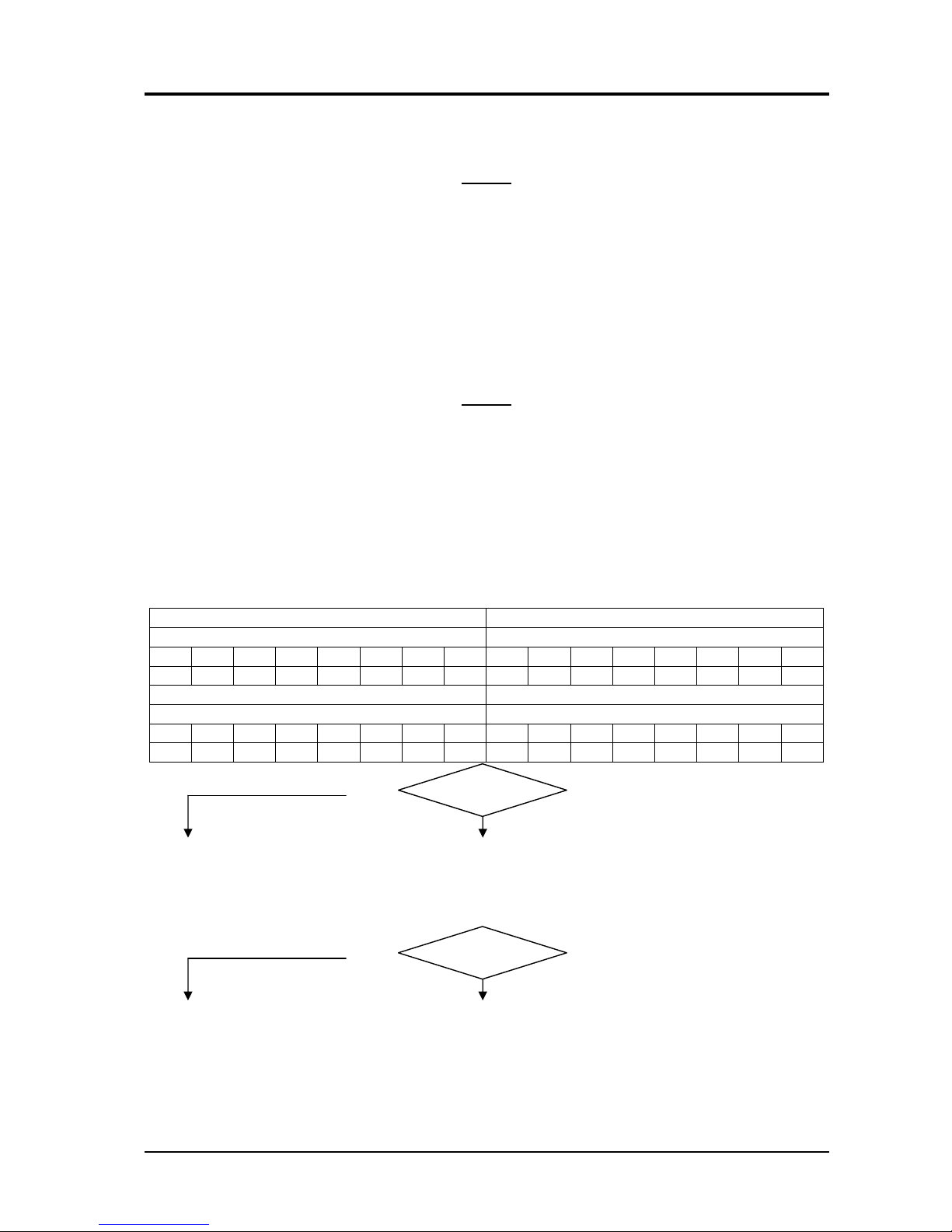
Switch 45 position = 1 Switch 45 position = 2
Switch 44 positions Switch 44 positions
1 2 3 4 5 6 7 8 1 2 3 4 5 6 7 8
16,8 17,1 17,3 17,6 17,9 18,4 18,7 19,3 20,3 20,6 21 21,3 21,8 22,5 23 23,8
Switch 45 position = 3 Switch 45 position = 4
Switch 44 positions Switch 44 positions
1 2 3 4 5 6 7 8 1 2 3 4 5 6 7 8
25,3 25,9 26,3 26,9 27,3 28,9 29,5 31 33,5 34,3 35,2 36,2 37,3 39,6 40,8 43,6
Correct?
NO
Correct?
YES
♦Regular operation.
INPUT CONTACTOR (51) TEST.
Contactor (51) coil terminals = 28 Vac, contactor closed, with start button pressed.
YES
NO
♦Check the wiring between the contactor (51) coil, connector J7 on control board
(4) and connector J1 on timing board (62).
♦Check the supply voltage for control board (4), performing if necessary the
CONTROL BOARD (4) POWER SUPPLY TEST in par. 3.3.1.
♦Check wiring between switches (44) and (45) and J2 and J12 on control board (4).
♦Check efficiency of start command, performing if necessary the tests in par. 3.3.4.
3.302.200 29/04/05
CEBORA S.p.A. 15
♦With the power source off and unplugged, check the resistance between the
terminals of the contactor (51) coil. Correct value = approximately 3.5 ohm. If 0
ohm (short-circuit), replace contactor (51) and control board (4).
♦With the power source off and unplugged, check the resistance between the terminals of the
contact (51) coil. Correct value = approximately 3.5 ohm. If incorrect, replace contactor (51).
VOLTAGE TO SECONDARY CIRCUIT OF THE TRANSFORMER (5) TEST.
Disconnect terminals of the secondary transformer (5) circuit from the rectifier bridge (56).
Terminals of the secondary transformer (5) circuit = alternating voltage (Vac) values as
shown in the table, with start button pressed, open-circuit power source and rated mains
voltage.
NOTE
The table shows the value of the three alternating voltages measured at the secondary circuit;
if these are different (marked by an asterisk (*)) the table gives their average.
This average is thus slightly different from the value of each individual phase measured.
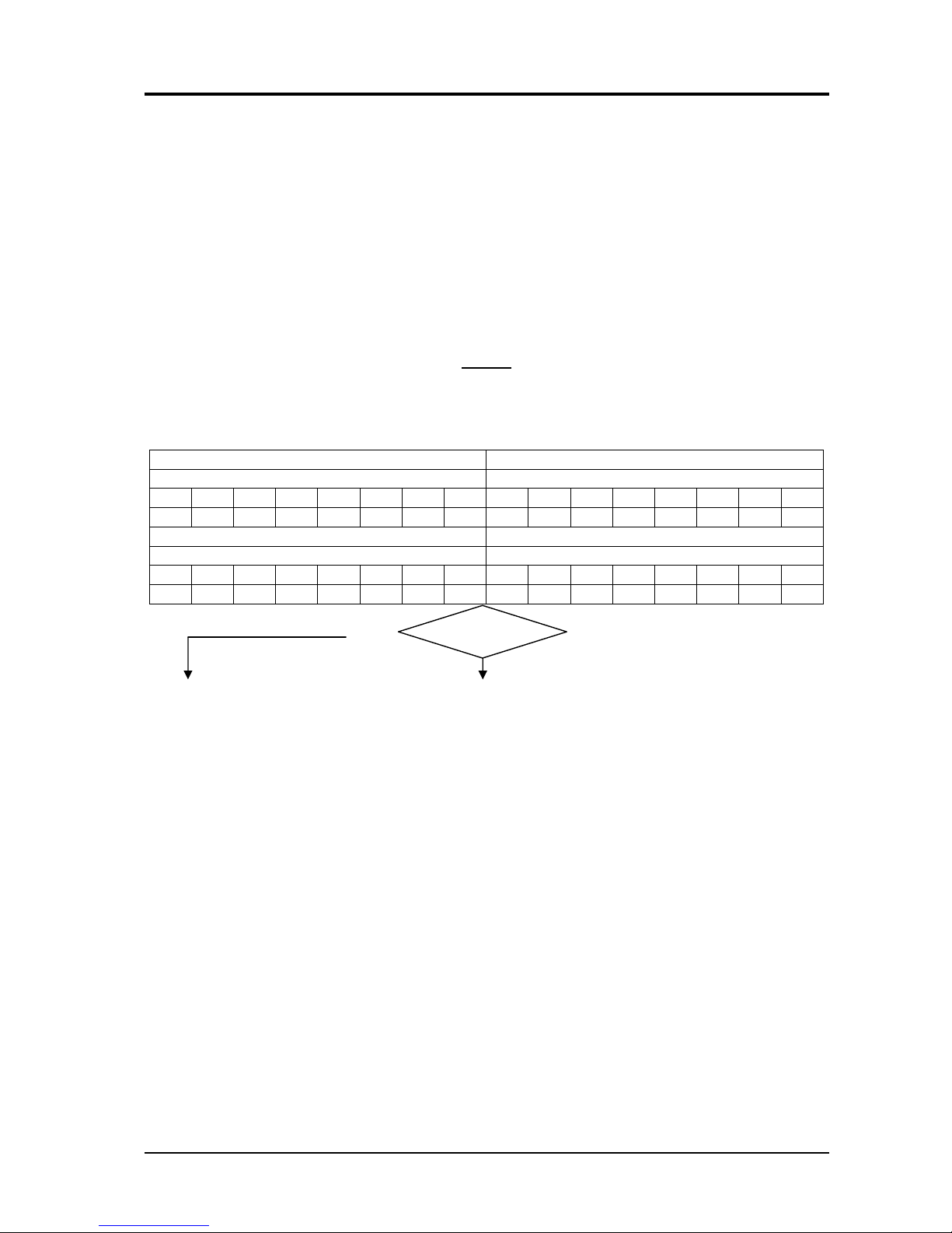
Switch 45 position = 1 Switch 45 position = 2
Switch 44 positions Switch 44 positions
1 2 3 4 5 6 7 8 1 2 3 4 5 6 7 8
13,4 13,6* 13,7* 13,9 14,1* 14,5 14,8* 15,2 16 16,3* 16,6* 16,8 17,1* 17,7 18,1* 18,6
Switch 45 position = 3 Switch 45 position = 4
Switch 44 positions Switch 44 positions
1 2 3 4 5 6 7 8 1 2 3 4 5 6 7 8
19,7 20,1* 20,4* 20,9 21,3* 22,3 22,8* 23,8 25,7 26,4* 27,1* 27,7 28,5* 30,2 31,1* 33
Correct?
NO
YES
♦Check the wiring between the secondary transformer (5) circuit and rectifier (56).
♦Check the efficiency of the rectifier bridge (56).
♦Check the wiring between the negative terminal of rectifier bridge (56), choke
(53) and output terminal (-)(V) of the power source, and between the positive
terminal of rectifier bridge (56), shunt (23) and central torch adapter (+)(G). If
you find loose connections, tighten them and replace any components with
damaged terminals.
♦Check the wiring between power cord, contactor (51), switches (44) and (45) and primary
winding of the transformer (5).
♦Make sure the primary circuit of the transformer (5) is properly connected on the voltage
change terminal board (59), and that the position of the voltage change (59) matches the
mains voltage.
♦Check delta connection of the windings that make up the secondary transformer (5) circuit.
♦Check the efficiency of switches (44) and (45); especially make sure there are no signs of
burned or misshapen contacts. For the test use the tables in the electrical diagrams in par. 5. If
necessary replace the defective switch.
♦With the power source off and unplugged, check the efficiency of the contacts on contactor
(51), tripping it manually and checking whether the resistance on each contact is
approximately 0 ohm. If you find burnt contacts or have difficulty moving the mobile
equipment, replace the contactor (51).
♦Replace the transformer (5).
3.302.200 29/04/05

CEBORA S.p.A. 16
3.3.8 - In resistive load operation, the output voltage is not regular.
NOTE
Only the test loaded at the maximum output voltage is described below, and thus at the
maximum current of the power source, since it is assumed that the OPEN CIRCUIT
OPERATION TEST in par. 3.3.7. has been successfully completed, and thus the connections,
turn ratio and operation of the transformer (5) are all assumed correct.
OUTPUT VOLTAGE TEST ON RESISTIVE LOAD.
Set the manual program (P00 on display (H)), switches (44) and (45) in the positions shown
in the table, and use a resistive load capable of withstanding the maximum current of the
power source. The appropriate values are shown in the table.
Power source output terminal (V)(-) and power source output terminal (G)(+) = direct current
values as shown in the table, with start button pressed.
switch 44
position switch 45
position resistive load
resistance power source output
current (Adc) power source output
voltage (Vdc)
8 4 0,085 ohm 400 +34
Correct?
NO
YES
♦Regular operation.
♦Make sure the connections between the primary circuit of transformer (5), switches (44) and
(45) and the voltage change terminal board (59) are intact. If you find loose connections,
tighten them and replace any components with damaged terminals.
♦Check the efficiency of switches (44) and (45), especially make sure there are no signs of
burned or misshapen contacts. For the test use the tables in the electrical diagram in par. 5. If
necessary replace the defective switch.
♦With the power source off and unplugged, check the efficiency of the contacts of contactor
(51), tripping it manually and checking whether the resistance on each contact is
approximately 0 ohm. If you find burnt contacts or have difficulty moving the mobile
equipment, replace the contactor (51).
♦Check the wiring between the secondary winding of transformer (5) and rectifier bridge (56).
If you find loose connections, tighten them and replace any components with damaged
terminals.
♦Check the efficiency of the rectifier bridge (56).
♦Make sure connections are intact between the negative terminal of rectifier bridge (56), coke
(53) and output terminal (-)(V) of the power source, and between the positive terminal of
rectifier bridge (56), shunt (23) and torch central adapter (+)(G). If you find loose
connections, tighten them and replace any components with damaged terminals.
♦Replace the transformer (5).
3.302.200 29/04/05

CEBORA S.p.A. 17
3.3.9 - In synergic mode, he welding quality is not satisfactory, the wire speed is not suited
to the output current.
NOTE
The parameters entered into the synergic programs are drawn from experience, and thus some
operators may find themselves working in ideal conditions, while others may need to make slight
changes.
For this reason the possibility remains to alter, to a small degree, the ratio between wire speed
and welding current within synergic programs. This value may be changed using the knob (P).
SYNERGIC PROGRAM PARAMETERS TEST.
Correct?
In synergic mode, the parameters saved in the selected program reflect the actual welding
conditions.
YES
NO
♦Select the program that best meets your needs and set the correct parameters (see
Instruction Manual and the table provided within the wire feeder unit).
♦Make sure the wire feeder motor is working properly, performing if necessary the test in par.
3.3.6.
♦Make sure the control panel is working properly (see par. 3.3.3).
♦Replace motor control board (4).
3.3.10 - Arc difficult to strike, the arc goes out immediately after lighting.
NOTE
In the power sources art. 957 the “Soft Start” function is included in the work programs and is
adjustable via the control panel (see Instruction Manual).
The choke (53) has two intermediate sockets to maximize welding as the material being used
changes. These outputs may also be used for easier welding starts.
Therefore, when dealing with start-up problems and difficulty in maintaining the arc, we
recommend:
−Make sure the “Soft Start” function adjustment is working properly, performing welding tests
with various setting values.
−Carry out welding tests, changing the working program with one similar to the one being
used, if available, and adjusting the knob (P) to improve the welding conditions.
−Check the compatibility of the torch with the type of welding being carried out, and especially
matching the torch nozzle with the wire being used.
−Check the wear status of the torch and its components, replacing them if necessary.
−Replace control board (4).
3.302.200 29/04/05
CEBORA S.p.A. 18
3.3.11 - When start button is released, the wire sticks to the workpiece (ineffective motor
braking). NOTE
The “Burn-Back” function is included in the working programs and is adjustable via the
control panel (see Instruction Manual).
With this function the power source delays stopping current generation during the slowdown
of the wire output from the torch, since even though it brakes after welding, the wire feeder
motor still requires a certain amount of time to come to a complete stop.
This time depends on various circumstances such as the type of torch, size of the wire coil,
type of wire, wire speed during welding, etc.
Thus if the wire sticks to the workpiece at the end of the welding process, consider the
aforementioned conditions and perform the following test.
WIRE FEEDER MOTOR (403) BRAKING TEST.
Correct?
Control board (4), connector J8 terminals 1 and 2 (gnd) = fig. 5.2.1, when the start button is
released, with the power source open-circuit (no wire in the torch). The wire feeder motor
stops immediately (braking time <200 msec.).
YES
NO
♦If you encounter fig. 5.2.2 (the motor slows from its own inertia), the braking
circuit on the control board (4) does not work properly, replace control board (4).
♦Make sure that there are no mechanical impediments preventing the wire coil from stopping
despite the braking action of the motor (ex.: sliding by wire feeder rollers, improperly
adjusted roller spring).
♦Replace the control board (4) and/or motor (403).
3.302.200 29/04/05

CEBORA S.p.A. 19
3.4 - Alarm signals.
3.4.1 - Led (F) lit = transformer (5) temperature too high, or wire coil cover open, or
cooling liquid flow low, or fuse on 16 Vac power supply tripped.
This signal is activated by four different situations:
−temperature of the transformer (5) above allowed limits, as detected by the thermostat inserted
on the windings of transformer (5);
−safety cover of the wire feed unit open, detected by the safety switch (46) on the wire feeder
guard;
−low flow of cooling liquid, detected by the cooling unit flow meter connected to connector
(17) of the power source (if no cooling unit is present, connector (17) must be connected to
the plug (16) provided);
−fuse on the 16 Vac secondary circuit of the service transformer (55) interrupted, thus no 16
Vac service voltage.
The alarm is automatically reset when the cause of the alarm is eliminated, but the power
source will only begin operating after pressing the start command again.
If the alarm occurs repeatedly, we recommend that you:
−Make sure the fan (58) is working properly.
−Make sure that air is flowing properly and that there is no dust or other obstacles to cooling.
−Make sure that the working conditions comply with the specified values, especially observing
the “duty cycle”.
−Make sure that the thermostat mounted on the transformer (5) is properly assembled and
working properly; its contact must be closed at ambient temperature.
−Make sure the safety switch (46) and the wire feed unit guard are in good condition and
properly mounted. With the guard closed the contact of switch (46) must be closed. If
incorrectly positioned, correct the position; replace if defective.
−Check on terminals 7 and 8 of J2, control board (4), voltage = approximately 16 Vac (no
alarm present). If incorrect, replace the control board (4). If incorrect, check the wiring
between terminals 7 and 8 of J2 control board (4), switch (46) on the guard of the wire feed
unit, thermostat on the transformer (5), flow meter on the cooling unit connected to connector
(17) of the power source, connector J1 of timing board (62) and 16 Vac secondary circuit of
the service transformer (55).
−Make sure the fuse on the 16 Vac secondary circuit of the service transformer (55) is intact. If
interrupted, before replacing it check the resistance on terminals 1 and 2 of J1 on timing board
(62), in the following conditions:
−With plug (16) removed from connector (17) on the power source: correct value = >Mohm
in both measurement directions. If incorrect replace the timing board (62).
−With plug (16) inserted in connector (17) on the power source: correct values = from
approximately 1000 ohm to 5500 ohm, based on the position of the switches (44) and (45).
This resistance is determined by the circuits leading to connectors J2 and J12 of control
board (4), which become involved when the contacts of the safety devices (thermostat,
wire feed unit guard switch, and plug (16) in the socket (17)) are closed. If incorrect check
the wiring between J2 and J12 of control board (4), switches (44) and (45), timing board
(62) and service transformer (55), and replace control board (4) if necessary.
−Replace control board (4).
3.302.200 29/04/05

CEBORA S.p.A. 20
4- COMPONENTS LIST
4.1 - Power source art. 597 : see file ESP597.pdf enclosed at the end of the manual.
4.2 - Components table : see file ESP597.pdf enclosed at the end of the manual.
4.3 - Spare parts list.
Essential spare parts.
Rif. Code Description Qty
4 5605831 programmed control circuit 1
37 3055136 knob 1
43 3190006 switch 1
51 3190278 contactor 1
58 3165051 motor 1
61 3065118 fan 1
Recommended spare parts.
Rif. Code Description Q.tà
6 3060278 coil support 1
12 3160181 solenoid valve 1
40 5803982 handle 1
41 3060247 handle support 2
44 3190515 selector switch 1
45 3190511 selector switch 1
55 5610034 service transformer 1
62 5602211 timing circuit 1
4.4 - Fuse table.
Ref. Description Value
F1 power supply for primary circuit service transformer (55) 5 A. 500 V.
F2 power supply for fan (58) + cooling unit 5 A. 250 V.
F3 power supply for 16 Vac services 1 A. 250 V.
F4 control board (4) power supply (28 Vac) 12 A. 250 V.
3.302.200 29/04/05
Table of contents
Popular Welding System manuals by other brands

Miller Electric
Miller Electric Big Blue Air Pak Brochure & specs

ersa
ersa i-CON PICO user manual

Lincoln Electric
Lincoln Electric WELD-PAK 100 HD Operator's manual

STAMOS
STAMOS S-MMA-120B user manual

Miller
Miller XMT 450 CC Technical manual

stud welding products
stud welding products StudPro 2500XI Operator's manual

Lincoln Electric
Lincoln Electric MIG-PAK 10 Operator's manual

Parweld
Parweld XTI 160 instruction manual

EWM
EWM TIGSPEED OSCILLATION DRIVE 45 COLDWIRE operating instructions

Lincoln Electric
Lincoln Electric US-CW223 datasheet

RTRMAX
RTRMAX RTM525 Original instruction manual

Migatronic
Migatronic AUTOMIG 200 XE operating manual


