BRB Systems USA TX-101 User manual

1
BRB Systems USA Co.
Instruction Manual
TX-101 and RX-101 Wireless Button Release System
IMPORTANT: Read and understand this manual before assembling, installing or
using this system. Improper use of this system can cause serious injury.
Table Of Contents
Page
(1) Safety Information…………………………………………….2
(2) Installation…………………………………..……..…………….4
(3) Set Up………………………………………………………………..6
(3.1) RX-101 Receiver…………………………………...6
(3.2) TX-101 Transmitter……………………..……....8
(4) Operation………………………..……….........................14
(5) Maintenance……………………………….……………………17
(6) Warranty……………………………………………………….…18

2
(1) Safety Information
Make certain that any person assembling or installing this system has read and
fully understood this Instruction Manual. It is your guide to safe and proper
operation of this system.
TX-101 Transmitters are 6V powered by 4 AA batteries.
AA batteries are small but powerful and must be treated with respect.
Never short the ends of the battery together. Never burn the battery,
even when you think it is fully discharged.
Rx-101 Receivers sold as 12V are to be powered with 12V dc power
sources only.
The 12V dc power sources that may be used with the Receivers are; 12V
lead acid batteries, 12V regulated ac to dc power supplies and 12V dc
power directly from the trap.
12V lead acid batteries (such as car type batteries) contain acid and so
extreme care must be taken when handing them.
12V car batteries are capable of supplying large amounts of current and
care must be taken not to connect the + (red) and –(black) terminals
together.
RX-101 Receivers sold as 120V are to be powered with 120V ac power
sources only.
Do not defeat the safety purpose of the polarized or grounding type plug
fitted to this apparatus. If the provided plug does not fit into your outlet
consult a qualified electrician. Exterior 120V outlets should be GFCI
CAUTION:
This system is powered by electricity. To reduce the risk of
electric shock, do not remove any cover from the apparatus. There
are no user serviceable parts inside. Refer servicing to
BRB Systems USA Co.
BRB Systems USA Co.

3
protected for your safety. If the outlet is not GFCI protected then
contact a qualified electrician for rectification.
Protect the power cord from being walked on, pinched or damaged in any
way.
Disconnect this apparatus from its power source during lightning storms
or when unused for extended periods of time.
Use only the attachment parts/accessories supplied by BRB Systems USA
Co.
Do not allow liquid entry into the system components.
Ensure that the traps are disconnected from their power sources and
unloaded before connection of the Receiver or set up of the Transmitter.
Failure to do so could result in the unexpected operation of the trap
causing serious injury.
Ensure that the trap is disconnected from its power source and unloaded
and that it is completely disconnected from the Receiver before
attempting loading, maintenance or repair of the trap. Failure to do so
could result in the unexpected operation of the trap causing serious
injury.
Extreme caution must be taken when a manually loaded trap is in use.
This system is not able to determine whether a loader is ready for a
target to be launched. Inadvertent operation of the system may cause
serious injury to the loader.

4
(2) Installation
RX-101 Receiver
To use the cabling as supplied, each RX-101 Receiver should be mounted
vertically and within 10ft of the power and release connections of the trap.
To lengthen the power/release cabling use a connector that is rated for outdoor
use and meets current electrical standards. Ideally the Receiver antenna
should have an unobstructed line of sight to the Transmitter antenna.
To make the Receiver connections to your traps use the appropriate plug for
the trap. These parts can be purchased from your trap manufacturer or
dealer. Release plug and socket wiring diagrams for your trap can be obtained
from your trap manufacturer or dealer.
Single Trap Receiver Connections
Power From Trap
10ft long 4 core cable = Receiver power and trap release connections.
Red 12V +ve.
Black = 12V –ve.
White and Green = trap release connections. Orientation of the white and
green wires is not important.
Power From 120Vac Wall Outlet
10ft 120V ac power cord = Receiver power.
Plug into GFCI protected 120V outlet.
10ft 2 core cable = trap release connections. Orientation of the white and
green wires is not important.

5
2 Trap Receiver Connections
Power From Trap
10ft long 4 core cable = Receiver power and trap release connections.
Red 12V +ve.
Black = 12V –ve.
White and Green = trap release connections Trap A. Orientation of the white
and green wires is not important.
2 pin socket and plug = trap release connections Trap B. Orientation of white
and green wires is not important.
Make solder connection of customer supplied cable into plug from Trap B.
Power From 120Vac Wall Outlet
10ft 120V ac power cord = Receiver power.
Plug into GFCI protected 120V outlet.
10ft 2 core cable = trap release connections Trap A.
Orientation of wires is not important.
2 pin socket and plug = trap release connections Trap B.
Orientation of wires is not important.
Make solder connection of customer supplied cable into plug from Trap B.

6
(3) Set up
(3.1) RX-101 Receiver Set Up
The receiver identity and operation are set via the three 8 position dipswitches.
Receiver Dipswitch Settings
Switch numbers are printed on the body of the dipswitch.
SW3
1
2
3
4
5
6
7
8
SW3
CODE
CHN
CNH
CHN
CHN
CHN
CNH
CHN
The (7) CHN switches must match between, TX and RX and ALSO set the frequency
SW2
1
2
3
4
5
6
7
8
SW2
CODE
CODE
CODE
CODE
OFF
OFF
OFF
OFF
(5) CODE switches must match between TX and RX, but don't affect frequency
OFF
OFF
OFF
OFF
OFF
OFF
OFF
OFF
TRAP1 relay responds to button "A"
OFF
OFF
OFF
OFF
ON
OFF
OFF
OFF
TRAP1 responds to "B"
OFF
OFF
OFF
OFF
OFF
ON
OFF
OFF
TRAP1 responds to "C"
OFF
OFF
OFF
OFF
ON
ON
OFF
OFF
TRAP1 responds to "D"
OFF
OFFO
OFF
OFF
OFF
OFF
OFF
OFF
TRAP2 responds to "A"
OFF
OFF
OFF
OFF
OFF
OFF
ON
OFF
TRAP2 responds to "B"
OFF
OFF
OFF
OFF
OFF
OFF
OFF
ON
TRAP2 responds to "C"
OFF
OFF
OFF
OFF
OF
OFF
ON
ON
TRAP2 responds to "D"
SW1
1
2
3
4
5
6
7
8
SW1
OFF
OFF
OFF
OFF
OFF
OFF
OFF
OFF
TRAP1 Relay Closed Time 0.25 sec.
ON
OFF
OFF
OFF
OFF
OFF
OFF
OFF
TRAP1 Relay Closed Time 0.8 sec.
OFF
OFF
OFF
OFF
OFF
OFF
OFF
OFF
TRAP2 Relay Closed Time 0.25 sec.
OFF
ON
OFF
OFF
OFF
OFF
OFF
OFF
TRAP2 Relay Closed Time 0.8 sec.
OFF
OFF
OFF
OFF
OFF
OFF
OFF
OFF
TRAP1 Recock Time 0.5 sec.
OFF
OFF
OFF
OFF
ON
OFF
OFF
OFF
TRAP1 Recock Time 1.5 sec.
OFF
OFF
OFF
OFF
OFF
OFF
OFF
OFF
TRAP2 Recock Time 0.5 sec.
OFF
OFF
OFF
OFF
OFF
OFF
ON
OFF
TRAP2 Recock time 1.5 sec.

7
CHN Channel Dipswitches
The 7 CHN dip switches (switches 2-8 of dipswitch SW3) are the primary
method of Receiver identification. They set the frequency of the Receiver and
give 128 possible frequency variations. Using these settings for identification
eliminates cross calls between adjacent fields because each field can have a
different working frequency.
The CHN dipswitch settings on both the RX-101 Receiver and TX-101
Transmitter must match for the system to operate.
CODE Signal Encoding Dipswitches
The 5 CODE dipswitches (switch 1 on dipswitch SW3 and switches 1,2,3 and 4
on the dipswitch SW2) are the secondary method of receiver identification.
The 5 CODE switches set the encoding, do not affect the receiver frequency
and expand the possible number of individual identities to 4096. Unless you
expect to need more than 128 different identities it should not be necessary to
use the CODE dipswitches.
The CODE dipswitch settings on both the RX-101 Receiver and TX-101
Transmitter must match for the system to operate.
Which Button Operates Which Relay
Your equipment will come preset for this. However, if you want to change
which of the Transmitter buttons operate which trap relay within the Receiver,
switches 5,6,7 and 8 of dipswitch SW2 allow you to do this.
Relay Closed Time
Some traps require a longer time period than others that the relay must be
closed for the release of a target. Switches 1 and 2 of dipswitch SW1 allow for
each relay within the receiver to be individually set to a closed time of 0.25
seconds or 0.8 seconds.
Recock Time
Used for a Transmitter mode that releases automatic Following Pairs from the
same trap. When a Following Pair is called for, the time between the 1st and
2nd target release can be set to 0.5 or 1.5 seconds to allow the trap time to
recock. To do this set switches 5 and 6 of dipswitch SW1. This setting should
depend upon how fast your trap recocks and the preference of the shooter.
8
(3.2) TX-101 Transmitter Set Up
The Transmitter identity and operation are set via the three 8 position dipswitches
accessed by removing the battery cover and the batteries.
Transmitter Dipswitch Settings
Switch numbers are printed on the body of the dipswitch.
TOP
1
2
3
4
5
6
7
8
CODE
CHN
CHN
CHN
CHN
CHN
CHN
CHN
The (7) CHN switches must match between TX and RX, and ALSO set the RF frequency.
MIDDLE
1
2
3
4
5
6
7
8
CODE
CODE
CODE
CODE
OFF
OFF
OFF
OFF
The (5) CODE switches must match between TX and RX, but don't affect RF frequency.
BOTTOM
1
2
3
4
5
6
7
8
OFF
OFF
OFF
OFF
OFF
OFF
OFF
OFF
TRAP
ON
OFF
OFF
OFF
OFF
OFF
OFF
OFF
SKEET - Instant Release
ON
OFF
OFF
OFF
OFF
ON
OFF
OFF
SKEET - 1/6th second delay before the first release
ON
OFF
OFF
OFF
OFF
OFF
OFF
OFF
AMERICAN SKEET- Random Delay 0-1 second
OFF
OFF
OFF
OFF
OFF
ON
ON
OFF
INTERNATIONAL SKEET- Random Delay 0-3 seconds
OFF
ON
OFF
OFF
OFF
OFF
OFF
OFF
SPORTING
OFF
OFF
ON
OFF
OFF
OFF
OFF
OFF
SUPER SPORTING-1
OFF
OFF
ON
OFF
OFF
OFF
ON
OFF
SUPER SPORTING-2
OFF
OFF
OFF
ON
OFF
OFF
OFF
OFF
QUAD SPORTNG -1
OFF
OFF
OFF
ON
OFF
OFF
ON
OFF
QUAD SPORTING -2
OFF
OFF
OFF
OFF
OFF
ON
OFF
OFF
1/6th SECOND DELAY added before the first release (any game except Skeet)
OFF
OFF
OFF
OFF
OFF
OFF
OFF
ON
HOLD VOICE MODE

9
CHN Channel Dipswitches
The 7 CHN dip switches (switches 2-8 of the top dipswitch) are the primary
method of Transmitter identification. They set the frequency of the
Transmission signal and give 128 possible frequency variations. Using these
settings for identification eliminates cross calls between adjacent fields because
each field can have a different working frequency.
The CHN dipswitch settings on both the Receiver and Transmitter must match
for the system to operate.
CODE Signal Encoding Dipswitches
The 5 CODE switches (switch 1 on the TOP dipswitch and switches 1,2,3 and 4
on the MIDDLE dipswitch) are the secondary method of Transmitter
identification. The 5 CODE switches set the encoding, do not affect the
transmission frequency and expand the possible number of individual identities
to 4096. Unless you expect to need more than 128 different identities it should
not be necessary to change the CODE dipswitches.
The CODE dipswitch settings on both the Receiver and Transmitter must match
for the system to operate.
Select A Discipline BOTTOM Dipswitch
Each TX-101 Transmitter can control 1-4 traps and has different user
programmable settings for each discipline and each number of traps. Select
how you intend to use the product from the list below.
Selectable disciplines are:
Trap –1 trap
Skeet –Instant release–2 traps
American Skeet 0-1 sec random delay –2 traps
International Skeet 0-3 sec random delay- 2 traps
Sporting –2 traps
Super sporting 1 –3 traps
Super Sporting 2 –3 traps
Quad Sporting 1 –4 traps
Quad Sporting 2 –4 traps
The button layouts for each discipline are shown below

10
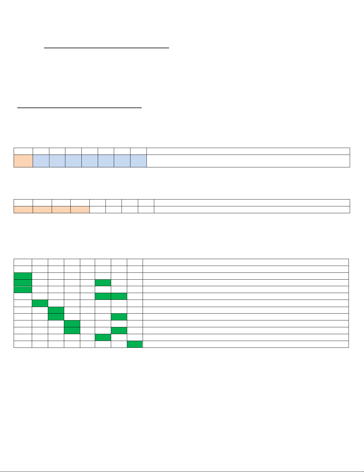
A
A
Single Trap Mode
Single
Press any button
Skeet Mode
Single
Press A or B
Doubles
Press either of the A+B Buttons
Button Layouts & Operating Sequences.
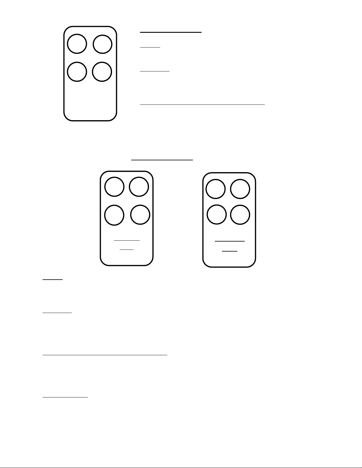
A
A
A
B
A+B
A+B
A
B
A+B
Report
Pair
Sporting Mode - 2 Traps
Single
Press A or B.
True Pair
Press A+B.
Report Pair Using Internal Microphone
Press Report Pair.
Press A or B of 1st trap to be released.
Report Pair Without Microphone
Press A or B to release 1st and 2nd traps manually.
11
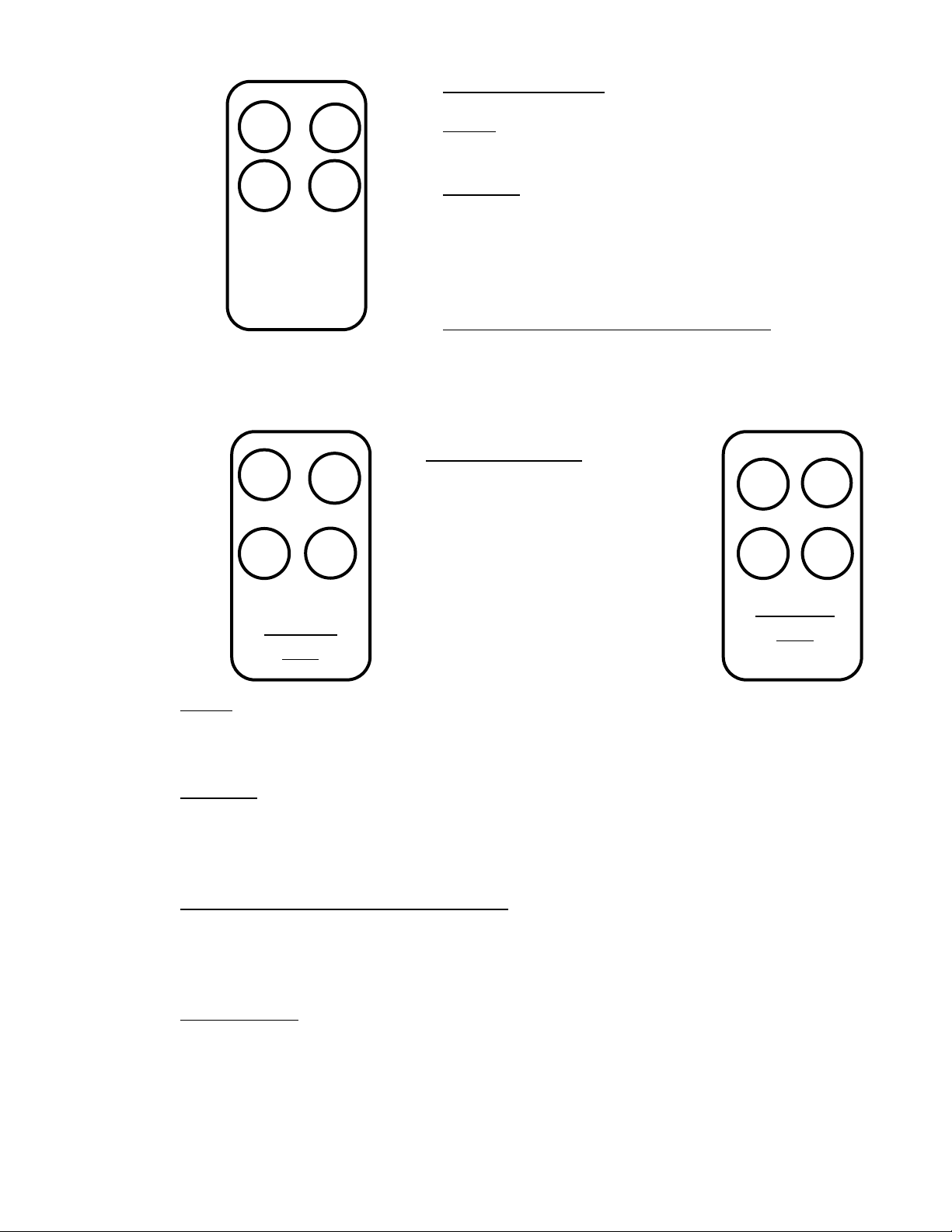
A+B
C
PAIR
A
B
Single
True
Pair
Report
Pair
Follow
Pair
Super Sporting 1 –3 Traps
Single
Press A, B or C.
True Pair
Press PAIR.
Press 2 traps of pair together.
Report Pair Using Internal Microphone
Press PAIR button.
Press and release 1st trap.
Press and release 2nd trap.
Press A, B or C to release 1st and 2nd traps manually.
A
C
B
Super Sporting 2 - 3 Traps
2nd button
press
1st button
press
Single
Press Single
Press A, B or C of trap to be released.
True Pair
Press True Pair.
Press 1st trap of pair.
Press 2nd trap of pair.
Report Pair Using Internal Microphone
Press Report Pair.
Press 1st trap to be released.
Press 2nd trap to be released.
Following Pair
Press Following Pair.
Press 1st trap to be released.
Press 2nd trap to be released.
12
C
Quad Sporting 1 –4 Traps
Single
Press and release A, B, C or D.
True Pair
Press & hold 1st trap of pair.
Press & hold 2nd trap of pair.
Release 1st button.
Release 2nd button.
Report Pair Using Internal Microphone
Press & hold 1st trap to be released.
Press & release 2nd trap to be released.
Release 1st button.
A
B
Single
True
Pair
Report
Pair
Follow
Pair
D
Quad Sporting 2—4 Traps
Single
Press Single.
Press A, B,C or D of trap to be released.
True Pair
Press True Pair.
Press 1st trap of pair.
Press 2nd trap of pair.
Report Pair Using Internal Microphone
Press Report Pair Button.
Press 1st trap to be released.
Press 2nd trap to be released.
Following Pair
Press Following Pair button.
Press 1st trap to be released.
Press 2nd trap to be released.
A
B
C
D
1st button
press
2nd button
press

13
Set the shooting disciplines by using switches 1-8 of the BOTTOM dipswitch.
See the ‘Transmitter Dipswitch Settings’diagram.
1/6th SECOND DELAY
To add a 1/6th second delay before the release of the first clay use switch 6 of
the BOTTOM dipswitch. This delay is not added to Instant, American or
International Skeet modes.
HOLD Voice Mode Switch 8 of the BOTTOM dipswitch is for Voice Release
Mode only. In this mode when a call is made and a target released the unit
will rearm for another release the same as the last release. This will continue
until a new button sequence is pressed.
Once the dipswitch settings have been made, install the 4 x AA batteries into
the rear of the unit. Take care to ensure correct orientation. Each battery
direction is clearly marked inside the battery cavity.

14
(4) Operation
RX-101 Receiver Operation
When powered 1 green led will light on the Receiver and will stay lit as long as
a good power level is maintained.
If battery voltage drops below 10.5V the power led will flash continuously to
signify a flat battery.
When a receiver relay closes a corresponding green led will light for the time
that the relay is closed. When the relay opens the same led will flash rapidly
for the duration that the recock timing has been set to before extinguishing.
TX-101 Transmitter Operation
The TX-101 has no power on switch. When you want to use it simply
press the appropriate button or sequence of buttons. The unit awakens
immediately.
For optimum performance stand facing toward the Receiver when holding the
TX-101, with the antenna in the vertical position.
See the Button Layouts and Operating Sequences diagrams in the Transmitter
Set Up section of this manual for the button press sequence of your set
discipline.
Low battery if a low battery voltage is detected a red led lights for 10 seconds
at the start of each button sequence.
Manual Operation
When a button is pressed, an led, or series of led’s will light. When the
sequence has ended the led(s) will extinguish.
If 1 or more button presses of a sequence are made, but the sequence is not
completed, the unit will wait for up to 10 seconds for the next button press.
If the next button press in not entered during that time the unit will reset
ready for the next sequence to begin.
If an illegal button press is made in a sequence, the unit waits for up to 10
seconds for the next correct button press and puts it into the sequence already
started. Effectively it ignores the wrong button press.

15
Once the button sequence has been correctly entered the TX-101 transmits the
information to the RX-101 Receiver. The time between the button being
pressed and the Receiver relay closing is less than 1/20th second.
Automatic Report Pair
In any of the Sporting modes an automatic Report Pair can be released via the
units internal report microphone.
PULL- 1st target is released –BANG - 2nd target is released.
When a Report Pair is released, if no gunshot is detected after 5 seconds the
unit will reset ready for a new sequence.
Automatic Following Pair An automatic Following Pair from the same trap can
be released in Super Sporting 2 and Quad Sporting 2 modes. In these modes
a second target will be released after the 0.5sec or 1.5 sec recocking time that
has been set in the RX-101 Receiver.
Voice Release Operation
When either the supplied lapel microphone, or the optional full size microphone
are plugged in to the TX-101 Transmitter, the unit automatically recognizes
that it is in voice release mode. A target now cannot be released manually.
To release a target the procedure is the same for each discipline. Press the
appropriate button or sequence that you want to be released. 1 second after
the button is pressed the microphone will listen for your call. Call for the
target and the target will be released.
If no call is detected after 30 seconds of the button press the unit will reset
and will require the button to be pressed again to release a target.
After the target has been released the unit will ignore the microphone for 2.5
seconds during which time no more targets can be released.
HOLD Voice Mode
If the HOLD mode has not been selected (switch 8 of the lower dipswitch), to
release another target another button press or sequence is required.
If the HOLD mode has been selected, after the target has been released and
the 2.5 seconds waiting period, the microphone will listen for another call.
When a call is detected the same target will be released as the last. This will
continue until a different button selection is made.
Skeet Sequence Voice Mode In voice release mode the button layout changes
to accommodate the addition of a 2 target user selectable Skeet sequence.

16
The button layout on the TX-101 now becomes:
When the SEQ button is pressed the Skeet Sequence Voice Mode is selected.
To release a HI target followed by a LOW target, press the SEQ button followed
by the HI button. The unit knows that the 2nd target is a LOW and so it does
not need to be pressed.
To release a LOW target followed by a HI target press the SEQ button followed
by the LOW button.
PULL–1st target is released - BANG - PULL–2nd target is released.
This mode can be used with the HOLD mode to repeat the sequence until a
new button sequence is selected.
A
A
A
B
A+B
SEQ

17
(5) Maintenance
The rugged manufacture of the BRB TX-101 and RX-101 should ensure many
years of trouble free use if it is not abused and given simple maintenance.
Do not allow any component to be immersed in water.
Regularly inspect the power/trap control cords for damage. If any wear
or damage is found, replace immediately.
There are no adjustments that can be made to the system by the user. Should
difficulty be found with the system operation, do not remove any of the system
covers. This will void the system warranty and may result in an electric shock
hazard.
Refer servicing to BRB Systems USA Co.

18
(6) BRB Systems USA Co. - Limited Warranty
This BRB Systems USA Co. product, supplied in the original packaging to the original purchaser, is warranted by BRB
Systems USA Co. against manufacturing defects in materials and workmanship for a limited warranty period of:
One (1) Year Parts and Labor.
This limited warranty begins on the original date of purchase and is valid only on products purchased and used in the
USA.
This warranty will terminate automatically prior to its stated expiration if the original purchaser sells or transfers the
product to any other party.
BRB Systems USA Co. will repair or replace this product, at our option and at no charge as stipulated herein, with new
or reconditioned parts or products if found to be defective during the limited warranty period specified above.
All replaced parts and products become the property of BRB Systems USA Co. and must be returned to BRB Systems
USA Co.
Replacement parts and products assume the remaining original warranty or ninety (90) days, whichever is longer.
This limited warranty covers defects in materials and workmanship encountered in normal use of this product and
shall not apply to defects or injuries caused by the following, including, but not limited to: damage which occurs in
shipment; delivery and installation; applications and uses for which this product was not intended; product alterations
not authorized by BRB Systems USA Co.; cosmetic damage or exterior finish; accidents; neglect; fire; water damage;
vermin or insect infestation; lightning or other acts of nature; use of products, equipment systems, utilities, services,
supplies, accessories, applications, installations, repairs, external wiring or connectors not supplied or authorized by
BRB Systems USA Co. which damage this product or result in service problems; incorrect electrical line voltage;
fluctuations and surges; customer adjustments and failure to follow operating instructions, cleaning, maintenance and
environmental instructions that are covered and prescribed in the Instruction Manual.
BRB systems USA Co. does not warrant uninterrupted or error-free operation of the product.
BRB Systems USA Co. shall not be liable for loss of revenue or profits, failure to realize savings or other benefits, or any
other special, incidental or consequential damages caused by the use, misuse or inability to use this product,
regardless of the legal theory on which the claim is based, even if BRB Systems USA Co. has been advised of the
possibility of such damages. Nor shall recovery of any kind against BRB Systems USA Co. be greater in amount than
the purchase price of the product sold by BRB Systems USA Co. Without limiting the foregoing, the purchaser assumes
all risk and liability for loss, damage or injury to purchaser and purchaser’s property and to others and their property
arising out of the use, misuse or inability to use this product sold by BRB Systems USA Co. not caused directly by the
negligence of BRB Systems USA Co.
To receive warranty service contact BRB Systems USA Co. for problem determination and service
procedure. If it is determined that the product requires warranty service, ship the product, in its original
packaging or its equivalent, together with proof of purchase, prepaid insured to BRB Systems USA Co.
Products repaired or replaced under warranty will be returned to you, within a reasonable time, freight
prepaid.
To obtain warranty service contact BRB Systems USA Co. at:
brbsystemsusa@yahoo.com or call: 412 773-2128.
Other manuals for TX-101
2
This manual suits for next models
1
Table of contents
Other BRB Systems USA Receiver manuals

Popular Receiver manuals by other brands


Seav
Seav R 2295 Series quick start guide

evertz
evertz 7707AR-A Series manual

Voscom
Voscom VOS-1210FFDT Series installation manual

AV Access
AV Access 4KEX70-RX user manual

FirstSing
FirstSing IPUSH2TV V5 quick start guide

Alpha Communications
Alpha Communications TekTone NC505ES Installation & operating instructions