Breas Medical NIPPY+ Series User manual

Doc 0930 Technical Manual
for the
NIPPY+ Range of Ventilators
This manual covers all of the NIPPY+ range of ventilators
This manual contains confidential information
and it is supplied on the understanding that it
shall not be copied, loaned or distributed to any
other persons or organisations, in whole or in
part, without the written consent of:
Breas Medical Ltd
Unit A2, The Bridge Business Centre
Timothy’s Bridge Road
Stratford–upon-Avon
CV37 9HW
Tel: 01789 293460
www.nippyventilator.com
Version 10, December 2017

Contents
Introduction 1
Description 2 - 5
Service Menus
Time and Date 6
Service Period / Calibration 7
Diagnostic Screen 8
Alarm Log 9
Install Defaults 10
Fault Messages 11-12
Event Log 13
Opening the Case
Fig 1, Opening the Case 14
Fig 2, Inside the base 15
Fig 3, Inside the base –Control bd removed 16
Fig 4, Location of Components –Lid 17
Removal of Major Components 18-19
Preventative Maintenance Guide 20
Suggested Acceptance tests 22
Internal Battery 23
Replacement of Alarm Battery 24
Calibration 25
Theory of Operation 26
System Pneumatic Diagram 27
Block Diagram 28
Block diagram of Control Board 29
Block diagram of Command Board 30
Circuit Diagrams 31- 42
Specification 43
Spare Parts List 44

1
Introduction
The purpose of this manual is to enable suitably qualified competent technical
personnel to perform first line maintenance on the NIPPY+ family of
ventilators.
The NIPPY+ range consists of :- NIPPY 3+, NIPPY junior+, NIPPY St+ and
NIPPY S+. They all use the same hardware and service procedures.
Component level fault finding will not be considered. Due to the complexity of
the circuit boards used in the NIPPY+ range, it is not considered practical or
cost effective to try to trace faults to component level.
Second-hand or “service exchange” boards are not available.
This manual will deal with routine maintenance, calibration and replacement
of major components.
IMPORTANT
Read this manual before attempting service or repair of the NIPPY+
Please contact Breas Medical Ltd if training is required or you have any
questions.
NIPPY+ must be subjected to regular inspection according to Breas
Medical Ltd service instructions. Repairs shall be carried out in
accordance with this technical manual and any special service
instructions or bulletins provided by Breas Medical Ltd.
Before opening the case, disconnect the NIPPY+ from the mains supply.
Do not work on the NIPPY+ with the case open and the power supply
connected.
Make sure that all precautions to prevent Electrostatic Discharge (ESD)
have been taken.
Do not use explosive gases and/or fluids near the NIPPY+.

2
Description
The NIPPY+ range ventilators are intended to provide ventilation for non-
dependent, spontaneously breathing adult patients with respiratory
insufficiency, or respiratory failure.
The NIPPY+ range devices are pressure controlled, positive pressure
ventilators. They compress ambient air and deliver it to the patient through a
close fitting nasal mask or a tracheostomy. The output pressure, timing and
alarms can be adjusted by controls on the fascia panel. The Pressure,
estimated Tidal Volume, Rate and all settings are displayed on a colour LCD
(Liquid Crystal Display) screen.
The screen can be set to dim after a pre-set time (accessed via the user
preferences in the main menu). To restore the display, press any button once.
The basic ventilator settings can be achieved using the four buttons to the left
of the display. The four buttons to the right of the display adjust the alarms
and provide access to more advanced features and adjustments (accessed
via a menu).
NIPPY 3+ and NIPPY junior+ are normally supplied with an internal battery
fitted. This is available as an option on NIPPY ST+ and NIPPY S+.
All can run on an internal or external battery or both if extended run times or
extra back up is required.
All are capable of recharging their internal batteries and the external Lithium
ion packs. The internal battery has priority over the external one.

3
Modes of Ventilation
CPAP (Continuous Positive Airway Pressure) Constant
positive pressure is applied via the mask. No
respiratory support is given in this mode.
NIPPY 3+, NIPPY Junior+, NIPPY ST+.
Pressure Support IPAP (Inspiratory positive airway pressure) and EPAP
(Expiratory positive airway pressure) are set by the
physician. The ventilator augments the patient’s
spontaneous breathing.
Adjustable back-up rate takes over in the absence of
an inspiratory trigger.
NIPPY 3+, NIPPY Junior+, NIPPY ST+, NIPPY S+.
Pressure Control IPAP, EPAP and Ti are set by the physician. A timed
inspiration is cycled by the patients inspiratory effort.
Adjustable back-up rate takes over in the absence of
an inspiratory trigger.
NIPPY 3+, NIPPY Junior+.
IPPV (Intermittent Positive Pressure Ventilation) IPAP and
Ti are set by the physician. A timed inspiration is
cycled by the patient’s inspiratory effort. Patient
exhales to atmosphere via an exhale valve fitted in
the breathing circuit. EPAP is not used in this mode.
Adjustable back-up rate takes over in the absence of
an inspiratory trigger.
NIPPY 3+, NIPPY Junior+.

4
Alarms
Power Fail If the electrical power to the ventilator is interrupted, an audible
alarm will sound. This alarm will run for 5 minutes unless cancelled with the mute
button. Once cancelled the power fail alarm will not re-activate.
Low Internal Battery When running on its internal battery, the alarm will operate when
the battery is low. This could last for up to 1 hour. When the alarm becomes constant
there is approximately 10 minutes running time left.
Low External Battery When running on its external battery, the alarm will operate
when the battery is low. This could last for up to 1 hour. When the alarm becomes
constant there is approximately 10 minutes running time left.
Low Pressure A pre-set low pressure alarm is provided. If the control pressure falls
to below 50% of the set IPAP level for 10 seconds an audible and visual alarm will
operate.
High Pressure A pre-set high-pressure alarm is provided. If the pressure rises above
120% of the working pressure, an audible and visual alarm will operate after a 2 second
delay.
Breathing Circuit Disconnect A disconnection alarm is provided as a back up to
the high flow alarm. If the patients flow waveform indicates that a significant leak
maybe present in the breathing circuit an audible and visual alarm will operate.
The sensitivity of the alarm is adjustable.
Breathing Circuit Malfunction This alarm warns of a malfunction of the exhale
valve in the IPPV mode circuit.
High Flow alarm An adjustable alarm is provided to warn of excess inspiratory flow.
This is activated when the inspiratory flow exceeds the set high flow alarm level
for 5 seconds. An audible and visual alarm will operate.
Low Flow alarm An adjustable alarm is provided to warn of insufficient inspiratory
flow. This is activated when the inspiratory flow fails to achieve the set low flow
alarm level for 10 seconds. An audible and visual alarm will operate.
Apnoea Alarm An adjustable Apnoea alarm is provided. If an apnoea is detected an
audible alarm will sound with a visual indication on screen.
Max Breath Rate An adjustable maximum breath rate alarm is provided. If the max
breath rate is exceeded an audible and visual alarm will operate.
Fault The alarm may also be operated by an internal fault. In this case the fault will be
displayed on screen.
These alarms may be muted for approximately 2 minutes to allow for setting up of
the ventilator.
Low Internal Alarm/Memory Battery An intermittent alarm (short beep) with no
onscreen message indicates a depleted mains fail alarm battery. If the ventilator has
been stored for more than a few weeks the internal battery will self-discharge. In this
case the alarm will stop after the battery has recharged.

5
Estimated Tidal Volume
The estimated tidal volume is a calculated value, based on time and
calibrated flow values. The constant leak through the breathing circuit
exhalation port is subtracted from this calculation to give a reasonably
accurate estimation of tidal volume. If a different exhalation port is used (a
ventilated mask for example) this calculation may be affected by the possible
change in exhalation port flow rate. This must be taken into consideration
when reading the tidal volume.
A ventilated mask with a higher flow exhalation port will cause the estimated
flow reading to be slightly higher than normal.
Inspiratory Trigger
The NIPPY+ employs flow triggering, detecting the start of the patients’
inspiratory effort when the flow rate exceeds the level set by the Inspiratory
Trigger sensitivity.
Expiratory Trigger
The expiratory trigger is used in Pressure Support mode only. Towards the
end of inspiration, when the inspiratory flow rate drops to the baseline
(standing flow caused by exhale port leak) minus the expiratory trigger
sensitivity the ventilator will cycle into the expiratory phase.
The inspiratory and expiratory effort required to cycle the ventilator can be
adjusted via the Trigger option in the Menu.
For simplicity the trigger sensitivity is scaled 1 –10, with 10 being the most
difficult.
Battery Charging
Both internal and external batteries are of Lithium Ion construction. Charging is
fully automatic. When the ventilator is connected to mains power but not
running, batteries will be charged continuously. The internal battery is charged
to approx. 95%, and then the external battery (if present) is charged to the same
level, before switching back to internal to complete the charge. The charge will
be terminated when both batteries are fully charged.
Whilst the ventilator is running, the batteries are charged during the EPAP
period of the breathing cycle.
When the ventilator is switched off it is in standby mode. It will “wake up” every
16 seconds to check the state of its batteries and start a charge sequence if
necessary.
6
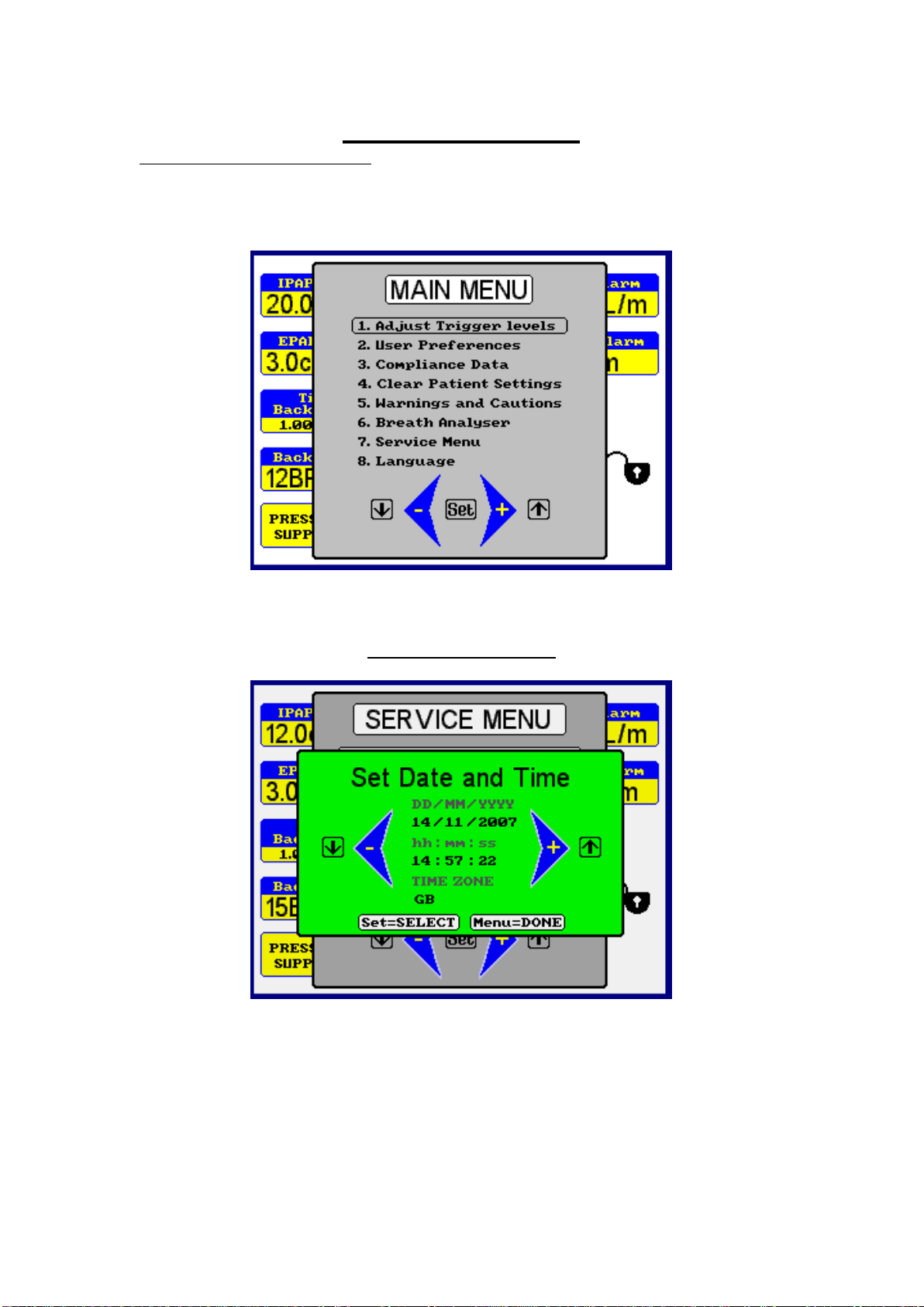
The Service Menu
Accessing the service menu
To access the service menu, power up the machine whilst holding down the
Hi and Lo alarm setting buttons (Menu and Mute on NIPPY S+ and ST+).
Press Menu and select Service menu from the main menu.
Set Time and Date
Press the set button to select the value and use the + and –buttons to adjust.
Time zone may be set for anywhere in the World.
Press menu to leave this screen.

7
Service Period
The service period screen shows the total running time and running time since
the last major service.
When a 10000 hour service has been completed, press the + and –buttons
together for 2 seconds. The current date will be entered into the service
record and the service indicator will be reset. This provides an on-screen
record of major services.
Calibration Screen
In this screen the calibration of the flow and pressure transducers is
accessed. The machine then generates its own pressure or flow to be
compared to a calibrated standard. Altering the blower speed varies the
pressure and flow. Use the Set button to move from blower speed to pressure
or flow. Use the + and –buttons to adjust the values.
Press and hold Hi and Lo alarm buttons for 2 seconds to restore default
calibration values.

8
Diagnostic Screen
This screen shows the following information:-
Box internal temp The internal temperature. If this value rises above
60 degrees, an alarm will be activated.
Blower current Current consumed by the blower
Pressure Error The pressure servo loop error. This should ideally
be close to zero.
PSU Voltage The internal power supply voltage. Nominally 24V
dc
Int. Li. Batt. Vlt. The internal lithium battery voltage, if present.
Nominally 18.75V.
Int. Li. Batt. Curr. Charge or operating current of the internal battery.
Ext. Li. Batt. Vlt. The external lithium battery voltage, if present.
Nominally 18.75V.
Ext. NiMh.Batt.V The external Nickel Metal Hydride battery voltage,
if present. Nominally 24V.
Ext. Pb.Batt.Vlt The external Lead Acid battery voltage, if present.
Nominally 24V.
Ext. Batt. Cur External battery current in Amps. A positive value
represents a charge current and negative
represents discharge. Charging is only possible for
Lithium batteries.
Charge Voltage Battery charging voltage. 20.5V fully charged.

9
Alarm Log
The alarm log shows the number of alarm events and the time and date of the
last occurrence.
Alarm Log Entry
Explanation
“Over Pressure”
Pressure exceeded 120% of IPAP setting
"Under Press."
Pressure failed to reach 50% of set IPAP level
"High Flow"
Flow exceeded the high flow alarm level. Disconnected or excessive
leak.
"Low Flow”
Flow failed to reach low flow alarm level for more than 10 seconds.
Airway blockage.
"Low Bat.V."
External battery voltage low
"Disconnection"
Breathing circuit disconnection.
"Mains -> Batt."
Auto switch to internal or external battery after mains failure.
"Defs.Loaded"
Default values loaded.
"Power Lost"
Power failure.
"L.Saved.Ld."
Last saved values loaded
"Press.Meas.Flt"
Loss of pressure signal
“Safe mode”
Blower at minimum speed following Press.Meas.Flt
"Blower Flt."
Blower controller fault or blower stopped.
"Blower Spd.Flt."
Error between blower speed command and actual blower speed.
"Box Ov/Un Tmp."
Internal temperature below 5 degrees or above 60 degrees.
"Main Power Flt"
Internal power supply voltage out of spec. Less than 22 volts or
greater than 26 volts.
"Int.Coms.Flt."
Communication failure between internal micros.
"Alarm PIC Flt."
Communication error with alarm micro.
"Alarm PIC Bat."
Internal alarm / memory back up battery voltage low or high.
"B.Ram0.Flt.";
Battery backed-up memory access fault.
"B.Ram1.Flt.";
Battery backed-up memory access fault.
"B.Ram2.Flt.";
Battery backed-up memory access fault.
"EE.Mem.Flt.";
Eprom memory access fault.
Machine loads default values.
10
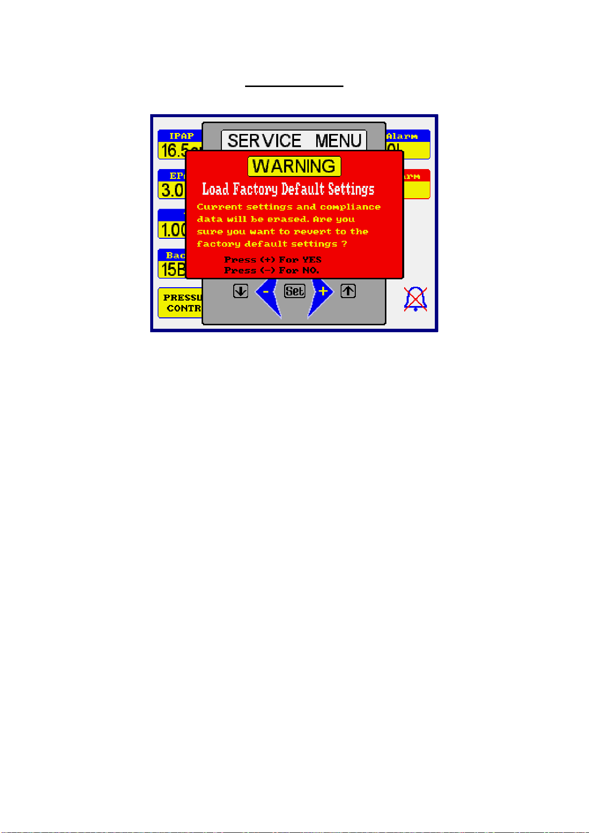
Install Defaults
If the ventilator is to be re-used for a different patient, the settings may be
restored to the factory defaults. These are:-
NIPPY 3+ NIPPY Junior+
IPAP 12cm 12cm
EPAP 3cm 3cm
Ti back-up 1.0 seconds 1.0 seconds
Mode Pressure Support Pressure Support
Hi Alarm 100L/min 60L/min
Lo Alarm 20L/min 20L/min
I Trigger 4 4
E Trigger 4 4
11
Fault messages
Fault Message
Fault Log Entry
Explanation
Probable Cause
Possible Remedy
Pressure Measurement
fault
"Press.Meas.Flt"
Loss of pressure signal
Pressure transducer pipe
disconnected.
Pressure transducer fault.
Reconnect pipe and restart
machine.
Replace power board.
Technical Fault
Vent Now in Safe Mode
Stop Using This Machine
Note 1
Safe Mode
Ventilator has set to minimum output
following a pressure measurement fault.
This prevents operation with no feedback.
Pressure transducer pipe
disconnected.
Pressure transducer fault.
Reconnect pipe and restart
machine.
Replace power board.
Blower Control fault
"Blower Flt."
Blower controller fault or blower stopped.
Seized Blower motor
Controller fault
Replace blower
Replace power board.
Blower speed fault
"Blower Spd.Flt."
Error between blower speed command
and actual blower speed.
Motor fault
Controller fault
Replace blower
Replace controller
Enclosure Temperature
fault
"Box Ov/Un
Tmp."
Internal temperature below 5 degrees or
above 60 degrees.
Machine covered, operated
in high ambient temperature
or cooling vents blocked.
Check operational
environment.
Check cooling fan operation
and vents.
Power supply fault
"Main Power Flt"
Internal power supply voltage out of spec.
Less than 22 volts or greater than 26 volts.
Power supply fault
Replace power supply
Control System fault
"Int.Coms.Flt."
Communication failure between internal
micros.
Failure of command micro
or power micro.
Replace command board or
power board.
Note 1: The technical fault message informs the user that the ventilator has switched to safe mode to protect against operation
without pressure feedback. The output is sufficient to clear exhaled gas only. If the original fault (pressure measurement fault) is still
present, this message will alternate with the pressure measurement fault message with each press of Mute. If the original fault has
cleared, only the technical fault message will be shown. Mute time in this configuration is reduced to 10 seconds. The pressure
measurement fault should be investigated.

12
Fault Message
Fault Log Entry
Explanation
Probable Cause
Possible Remedy
"Alarm PIC Flt."
Communication error with alarm micro.
Power interruption has
caused communication
error.
No action required. Unless
there are multiple occurrences,
then change command board
Alarm back up battery
fault
"Alarm PIC Bat."
Internal alarm / memory back up battery
voltage low or high.
Battery self discharges
when not in use.
Faulty battery
Run machine for 12 hours to
recharge battery.
Replace battery.
"B.Ram0.Flt.";
Battery backed-up memory access fault.
Machine failed to access
memory, probably because
of sudden power down.
No action required. Alternative
memory location will have
been used.
"B.Ram1.Flt.";
Battery backed-up memory access fault.
Machine failed to access
memory, probably because
of sudden power down.
No action required. Alternative
memory location will have
been used.
"B.Ram2.Flt.";
Battery backed-up memory access fault.
Machine failed to access
memory, probably because
of sudden power down.
No action required. Alternative
memory location will have
been used.
"EE.Mem.Flt.";
Eprom memory access fault.
Machine loads default values.
Machine failed to load from
Eprom memory.
Change command board.

13
The Event Log
The ventilator automatically stores every event during its lifetime. This event
log is not displayed on-screen but may be downloaded to a PC using
download lead part no. 0858.
The following events will be stored in the memory:-
Power on / off
Power interruptions
Any button push
Any adjustment
Any alarm event
Switching to battery and/or back to mains
Battery voltage when running on battery
Viewing of the service menu
Any calibration alteration
Pressure, and settings are logged at intervals when there are no other events
to log
These events are stored in chronological order.
To view the event log, the PC must have NIPPY for Windows software
loaded.
With the software running and the RS232 download lead connected, go to the
Tools menu and select Event Log.
Click on Get Latest to view the most recent events. Click on Previous or Next
to scroll through the events.
0086
100 - 240V
0.4 - 1.0 Amperes
47 - 63Hz
Fuse 2 x T1.6A SN
RS 232
Cooling Vent
1
2
3
1. Aux. Power - 24 Volt connection for external battery. Connect only
recommended batteries, part no 0910
2. RS232 Port - For connection to remote alarm or personal computer.
Isolated to 1500 Volts.
3. Power Inlet - Input mains power connector. Double fused and
fitted with connector retaining clip.
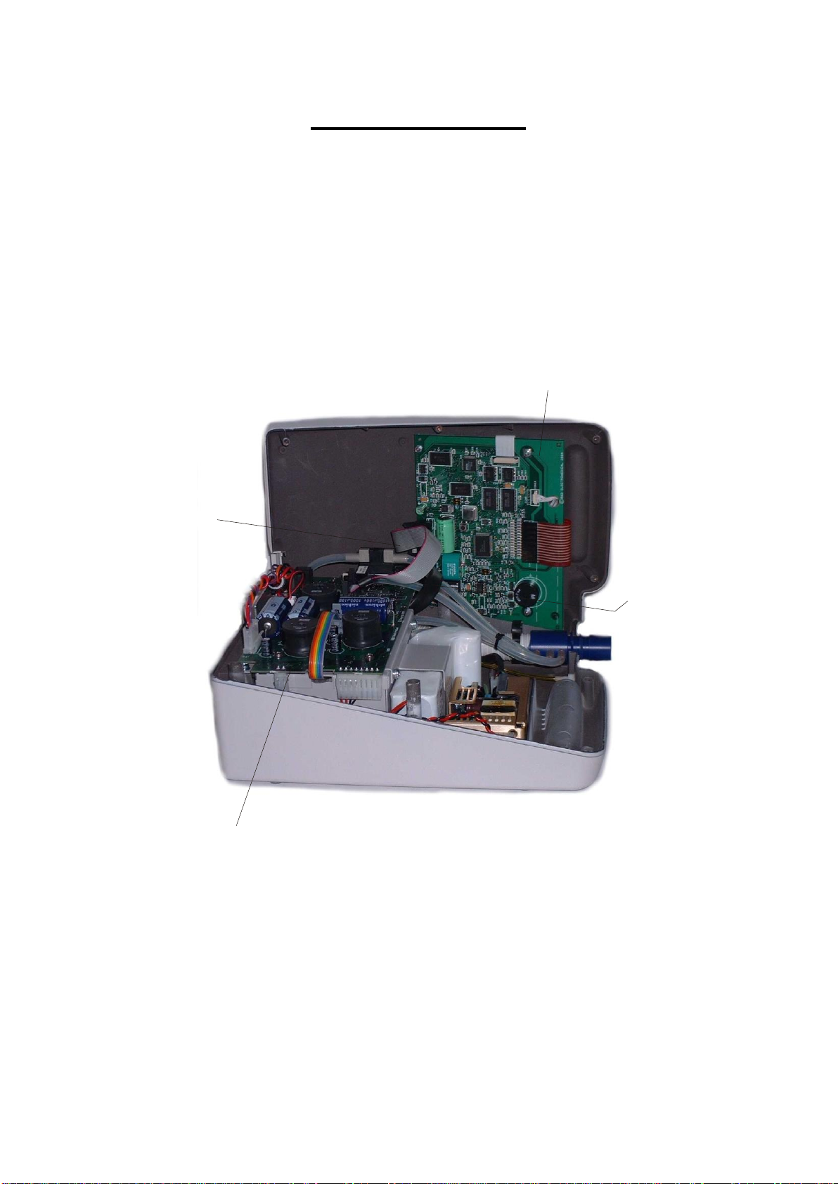
14
Opening the Case
IMPORTANT Disconnect the ventilator from the mains supply and / or
any external battery.
Invert the ventilator and remove the seven recessed, hexagon socket screws.
Stand the ventilator on its base and ease the lid upwards, away from the rear
panel. When the rear of the lid is clear of the rear panel, lift it from the left
hand side. Disconnect the RS232 connector (4) and the board to board ribbon
cable (3).
1
2
3
4
Fig 1.
Opening the NIPPY
1. Command board
2. Control Board
3. Board to Board Ribbon Cable
4. RS 232 Connection.
15
1
23
4
5
6
7
8
910 11 12
13
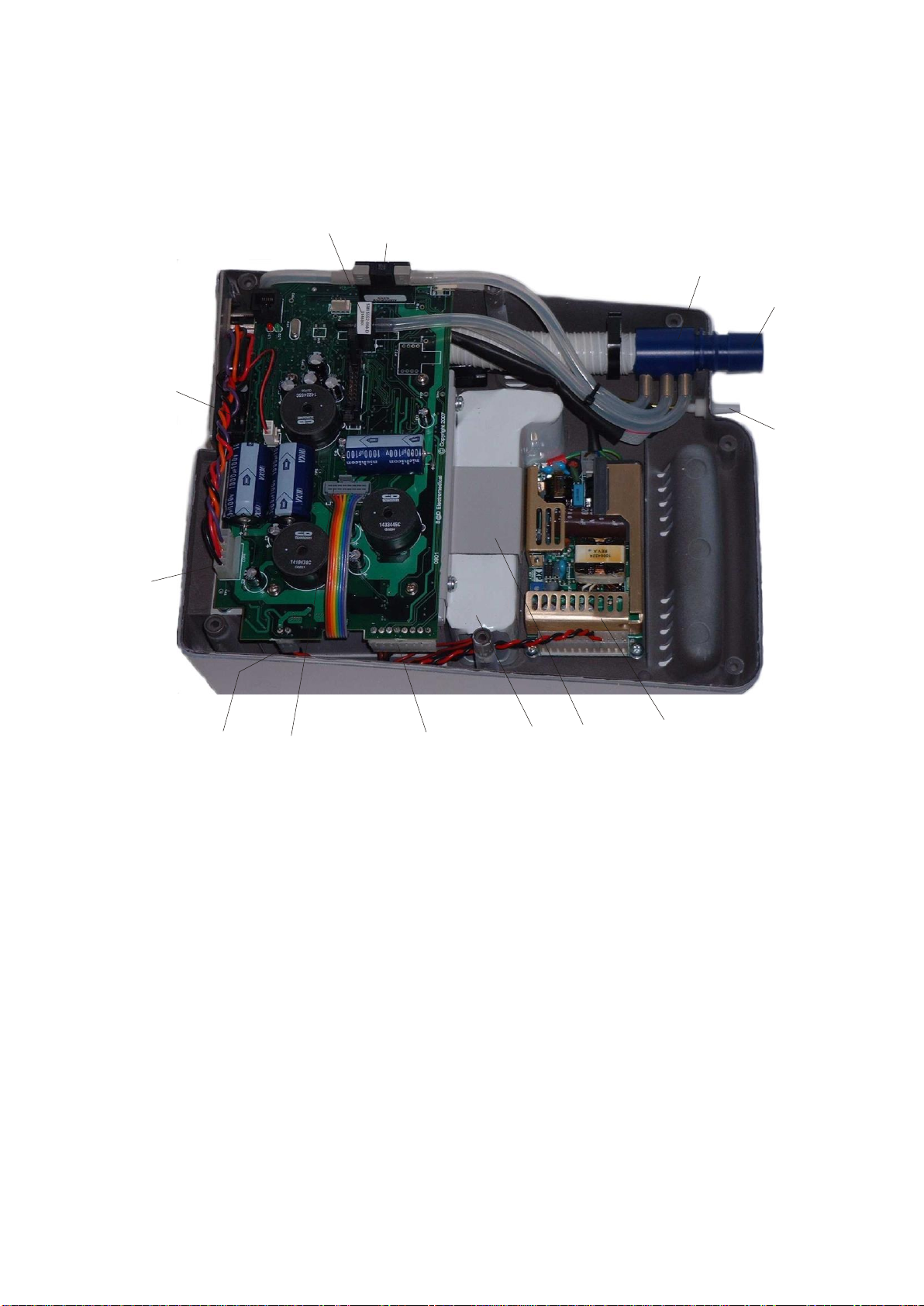
Fig 2.
Inside the Base
1. Mains Power Supply
2. Battery Clamp
3. Battery
4. Internal Battery Connector
5. Blower Connector
6. PSU Connector
7. External Battery Connector
8. Cooling Fan Connector
9. Pressure Transducer
10.Flow Transducer
11.Flow Head
12.Patient Outlet Port
13.IPPV Exhale Valve Control Line
(NIPPY 3+ and jnr+ only)
16
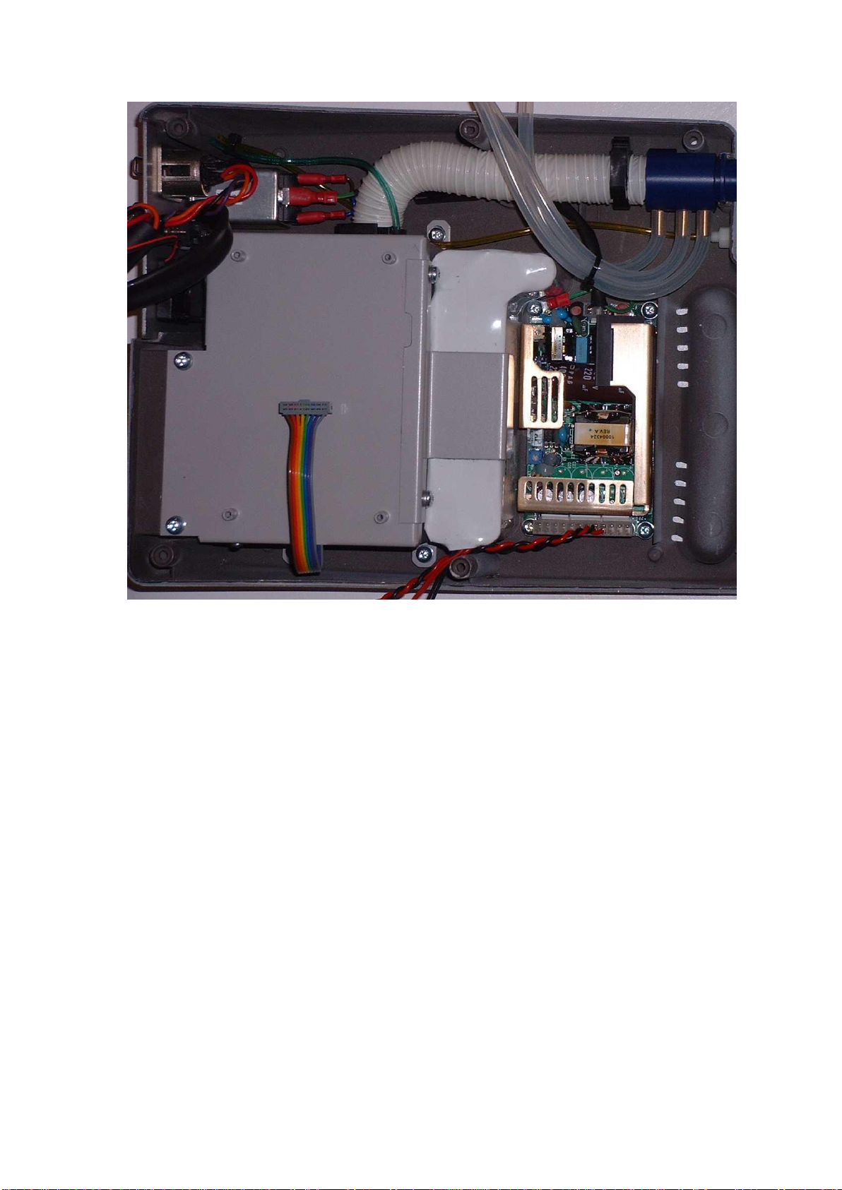
Fig 3.
Inside the base with the control board removed
17
1
2
3
4
5
6
7
8
9
10
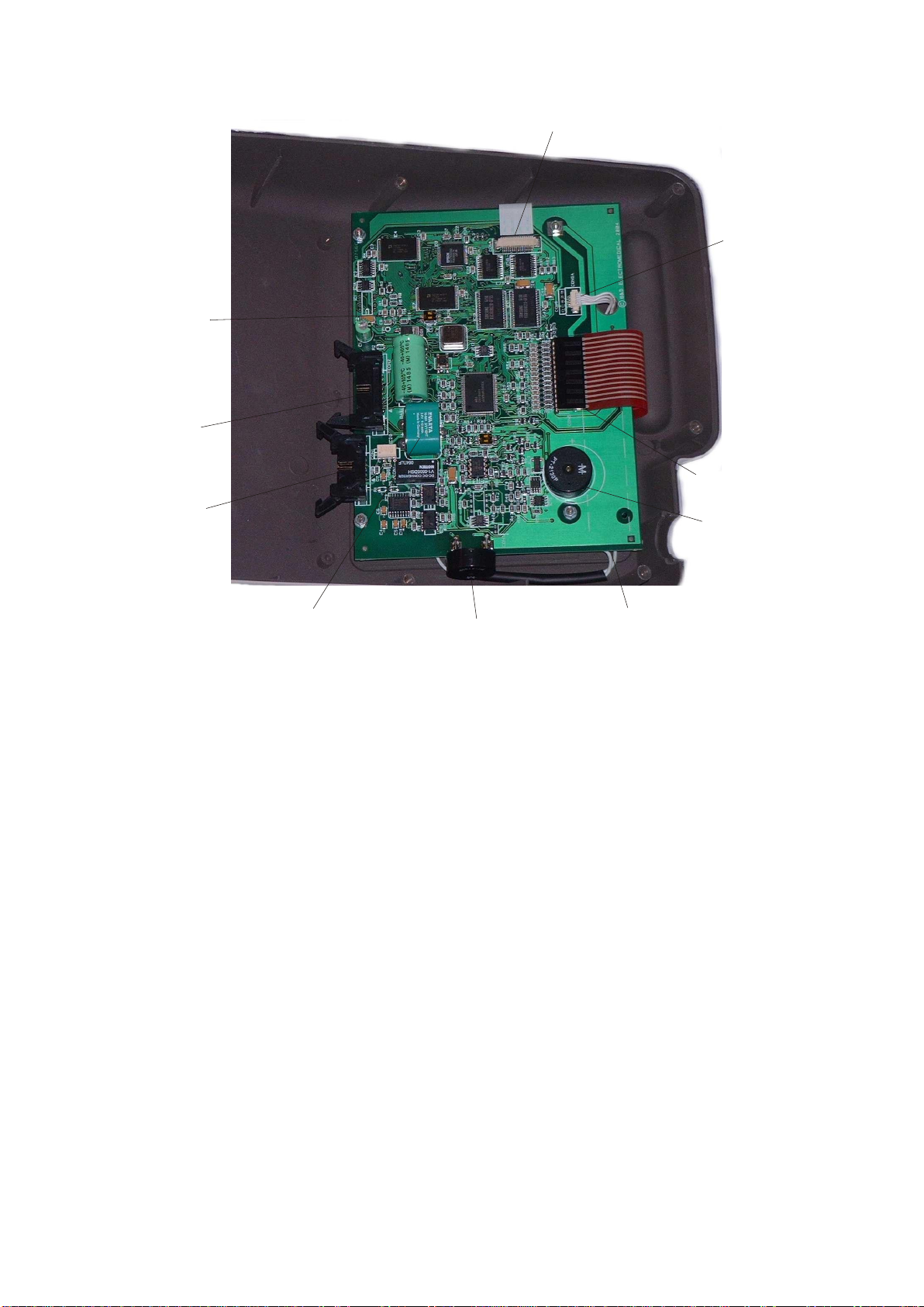
Fig 4.
Inside the Lid
1. RS 232 Port
2. Board to Board Ribbon
Connector
3. Memory Battery Switch
4. Display Connector
5. Display Back-light Connector
(Input)
6. Keypad Connector
7. Alarm Sounder
8. Display Back-light Connector
(Output)
9. Second Alarm Sounder
10.Alarm and Memory Back-up
Battery

18
Removal of major components
IMPORTANT Before opening the case, disconnect the NIPPY+ from the
mains supply.
Do not work on the NIPPY+ with the case open and the power supply
connected.
Make sure that all precautions to prevent Electrostatic Discharge (ESD)
have been taken.
Do not use explosive gases and/or fluids near the NIPPY+.
Unscrew the 7 case screws to separate the two halves of the case.
Disconnect the board to board ribbon cable and the RS232 lead (fig 1). Lay
the ventilator lid next to the base.
The Battery
Refer to fig 2
Disconnect the battery connector (4). There is no need to remove the board to
do this. Support the corner of the board with thumb and forefinger and gently
wiggle the connector downwards until it comes free.
Remove the battery clamp by removing the 2 M4 x 10 screws.
Remove the battery.
Reverse this procedure to refit.
The Power Supply
Refer to fig 2.
Disconnect the 2 way mains connector and the earth terminal.
Disconnect the 12 way output connector.
Remove the 4 securing screws and lift the power supply out of the case.
Reverse this procedure to refit.
The Control Board
Refer to fig 2.
Disconnect the internal battery first.
Disconnect the 3 Molex connectors. (Int Battery, PSU, Ext Battery, Cooling
fan).
Disconnect the blower connector.
Disconnect the 4mm silicon tubes from the pressure and flow transducers.
Disconnect the green and yellow small bore tubes from the Exhale valve
control solenoid. Located on the underside of the board.
Remove the 4 securing screws.
To refit:-
Connect the 2 small bore tubes. NOTE: the green tubes fits on the port
nearest the back edge of the board. The yellow tube fits on the adjacent port.
If the ends of the tubes are stretched, trim off approx. 2mm of tube.
Connect the PSU and connector.
Place the board into the lid and fit the 4 mounting screws.
This manual suits for next models
4
Table of contents


