BREEZISM AURORA BF9775L52-WH User manual
USE AND CARE GUIDE
BREEZISM
Item #0000 000 000
Item #0000 000 000
Item #0000 000 000
Model #BF9775L52-WH
Model #BF9775L52-MBK
Model #BF9775L52-BN
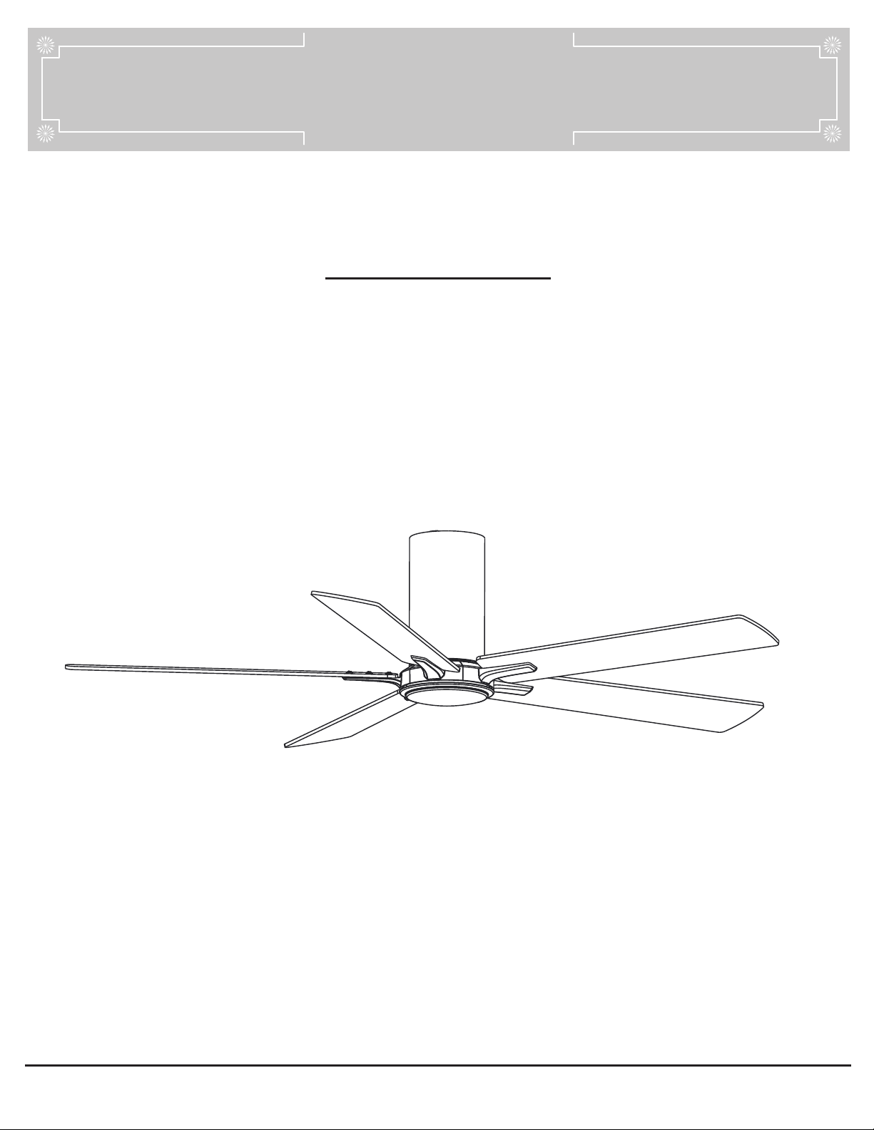
AURORA 52 INCH CEILING FAN

2
Installation .....................................................................
Table of Contents ..........................................................2
Safety Information .........................................................2
Warranty .........................................................................3
Pre-installation .............................................................. 3
6
Assembly ....................................................................... 7
Table of Contents
10Operation
Care and Cleaning 12
Troubleshooting 13
FCC Statement 14
......................................................................
.......................................................
...........................................................
............................................................
Safety Information
To reduce the risk of electric shock, ensure electricity has
been turned off at the circuit breaker or fuse box before you
begin.
All wiring must be in accordance with the National Electrical
Code “ANSI/NFPA 70” and local electrical codes.
Electrical installation should be performed by a qualified
licensed electrician.
The outlet box and support structure must be securely
mounted and capable of reliably supporting a minimum of 35
lbs (15.9 kg). Use only UL Listed outlet boxes marked
“Acceptable for Fan Support of 35 lbs. (15.9 kg) or less.”
Do not place objects in the path of the blades.
Do not use water or detergents when cleaning the fan or fan
blades. A dry dust cloth or lightly dampened cloth will be
suitable for most cleaning.
After making electrical connections, spliced conductors
should be turned upward and pushed carefully up into the
outlet box. The wires should be spread apart with the
grounded conductor and the equipment-grounding conductor
on one side of the outlet box and ungrounded conductor on
the other side of the outlet box.
All setscrews must be checked and retightened where
necessary before installation.
1.
2.
3.
4.
5.
6.
7.
READ AND SAVE THESE INSTRUCTIONS.
WARNING
:
To reduce the risk of personal injury, do not
To avoid possible electrical shock,
turn the electricity off at the main fuse box before
wiring.
CAUTION:
To reduce the risk of personal injury,
use only the screws provided with the outlet box.
To avoid personal injury or damage to the fan
and other items, use caution when working around or
cleaning the fan.
bend the blade brackets when installing the brackets
balancing the blades, or cleaning the fan. Do not insert
foreign objects in between rotating fan blades.
To reduce the risk of fire, electric shock
or personal injury, mount to outlet box marked
“ acceptable for fan support of 35 lbs. (15.9Kg)
or less” and use screws provided with the outlet box.
The fan must be mounted with a minimum
of 7 ft (2.1 m) clearance from the trailing edge of the
blades to the floor.
Changes or modifications not expressly
approved by the party responsible for compliance could
void the user’s authority to operate the equipment.
WARNING:
To reduce the risk of electrical shock or fire,
not use this fan with any solid-state fan speed control
device. It will permanently damage the electronic
circuitry.
WARNING:
To reduce the risk of electrical shock, this
must be installed with an lsolating wall control/switch.
WARNING
:
WARNING
:
CAUTION:
CAUTION:
CAUTION:

3
Warranty
Pre-InstallationPre-Installation
SPECIFICATIONS
TOOLS REQUIRED
Phillips
screwdriver
Electrical
tape
Wire
stripper
Flat blade
screwdriver
Step
ladder
NOTE: These are approximate measures. They do not
include amps and wattage used by the light kit.
52 in.
LOW
MED
HIGH
120
Fan size Watts RPM CFMSpeed Volts Amps N.W. G.W. C.F.
1.25cu ft.
0.056 3.2 70 2632
0.2 13 130 4645
0.38 28 170 5590
5.52kgs
(12.17lbs)
6.52 kgs
(14.37 lbs)
We warrant the fan motor to be free from defects in workmanship and material present at timeof shipmentfrom the factory for aperiod
of lifetimeafter the date of purchase by the original purchaser. We also warrant the lightkit,to be free from defects in workmanship and
material present at time of shipment from the factory for aperiod of five years afrer thedate ofpurchase by the original purchaser,
excluding any glass or acrylic components and wooden blades, tobe free from defects in workmanship and material at thetime of ship-
ment from the factory for aperiod of two year after the date of purchase by the original purchaser. We agree to correct such defects
without charge or at our option replace with a comparable or superior model ifthe productis returned. To obtain warrantyservice, you
must present a copy of the receipt as proof of purchase. All costs of removingand reinstalling theproduct are your responsibility. Damage
to any part such as by accident,misuse,improper installation or by affixing any accessories,isnotcovered by this warranty. Because of
varying climatic conditions this warranty does not cover any changes in brass finish,including rusting, pitting,corroding,tarnishingor
peeling. Brass finishes of this type give their longest useful life when protected from varying weather conditions, A certain amount of
“wobble” is normal and should not be considered a defect. Servicing performed by unauthorized persons shall render the warranty invalid.
There is no other express warranty. We hereby disclaim any and all warranties, including but not limited to those of merchantabilityand
fitness for a particular purpose to the extent permitted by law. The duration of any implied warranty which cannot be disclaimed is limited
to the time period as specified in the express warranty. Some states do not allow limitation on how long an imolied warranty lasts, so the
above limitation may not apply to you. The retailer shall not be liable for incidental, consequential, or special damages arising out of or in
connection with product use or performance except as may otherwisebe accorded by law. Some states do not allow the exclusion of
incidental or consequential damages, so the above exclusion or limitation may not apply to you. This warranty gives specific legal rights,
and you may also have other rights which vary from state to state. This warranty supersedes all prior warranties. Shipping costs for any
return of product as part of a claim on the warranty must be paid by the customer.

4
HARDWARE INCLUDED
NOTE: Hardware shown to actual size
Pre-Installation (continued)
AA
BB
CC
DD
EE
FF
GG
HH
Description
Blade screw (preassembled)
Light kit screw (preassembled)
Mounting bracket screw (preassembled)
Remote control holder mounting screws
Part
Remote battery cover screw (preassembled)
10+1 spare
15+1 spare
15+1 spare
3
3
3
2
1
Quantity
EE
HH
FF
GG
Wire nuts
BB
AA
CC
DD
Fiber washer
Blade screw

5
Pre-Installation (continued)
PACKAGE CONTENTS
Part QuantityDescription
1
Blades
Motor Assembly
5
C
D
E
Part
A
QuantityDescription
G
F
Mounting Plate
1
1
1
1
Motor Housing
Light Kit Plate
H
Light kit assembly
Remote control
1
1
B
Blade holder
5
A
C
B
F
D
G
H
I
E
J
J
12V Battery
1
IRemote control holder
6
Installation
WARNING: To reduce the risk of fire, electric shock, or
personal injury , mount the fan to an outlet box marked
acceptable for fan support. An outlet box commonly used for
the support of lighting fixtures may not be acceptable for fan
support and may need to be replaced. Ifin doubt, consult a
qualified electrician.
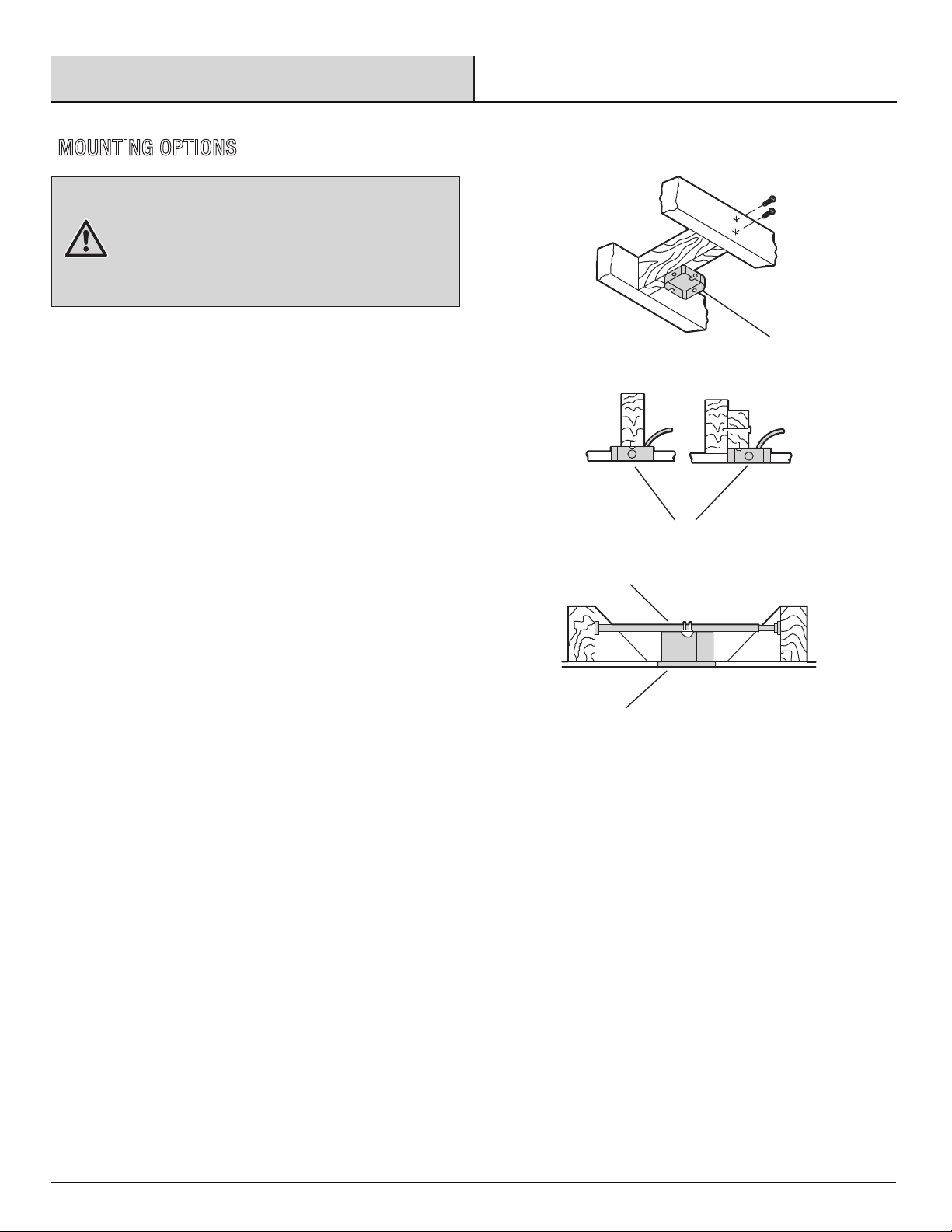
MOUNTING OPTIONS
1
1
1
2
If your ceiling fan does not have an existing UL-listed mounting
box, then install one using the following instructions:
□Disconnect the power byremoving the fuses or turning
off the circuit breakers.
□
□
Secure theoutlet box (1) (notincluded) directly to the
building structure. Use appropriate fasteners and
materials (notincluded). The outlet box and its bracing
must beable to fully support the weight of the moving
fan (at least 35 lbs.). Do not use a plastic outlet box.
The illustrations to the right show three different ways to
mount the outlet box (not included).
□To hang your fan where there is an existing fixture but no
ceiling joist, you may need an installation hanger bar (2)
(not included), as shown.
7
Assembly -Hanging the Fan
2
1
□
□
Make sure electricity is turned off at the main power box before
commencing work. Turn off the power by removing fuse or
turning off circuit breaker before installing the fan.
The lowest point on the fan blade must be at least 2.1 metres
(7 feet) from the floor.
Make sure that ceiling joists are strong enough and of adequate
size to support the weight of the fan of about 35 kg.
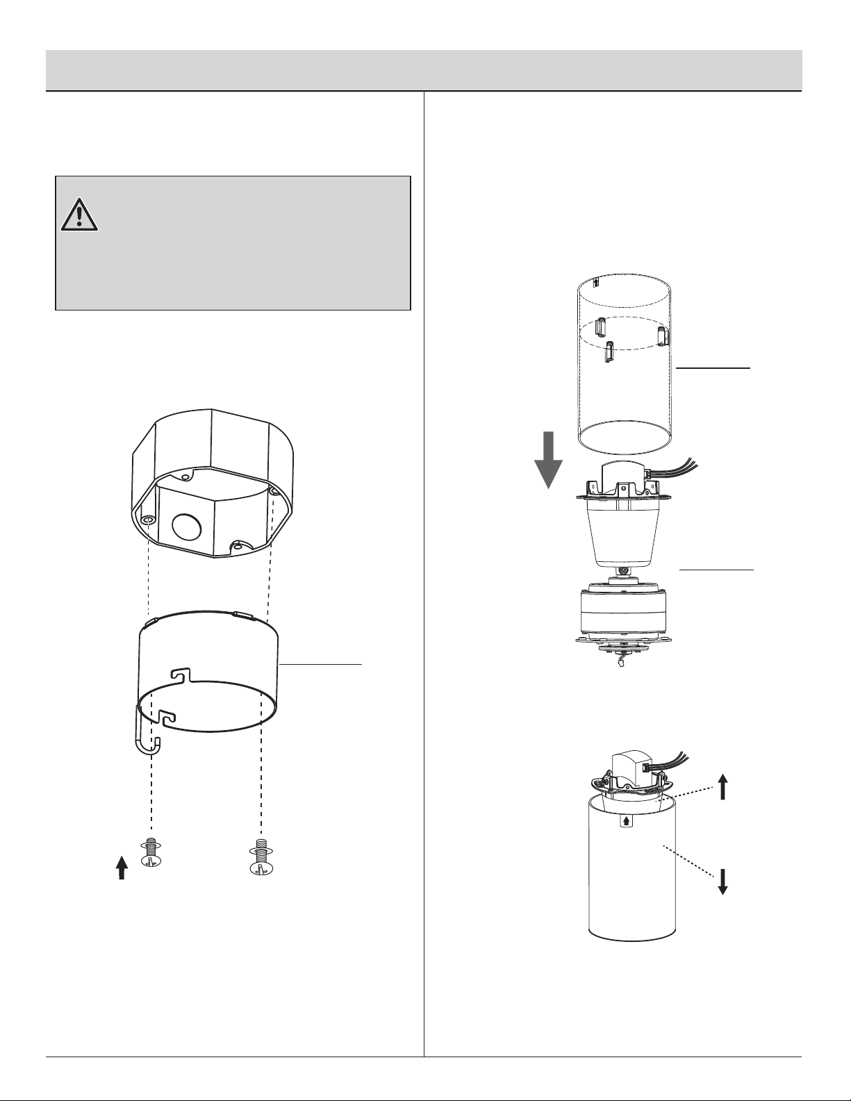
Secure the
mounting plate
(D) to the ceiling outlet box
with thescrews and washers provided with your outlet
box.Pull the 120-volt supply wires (the black, white and
ground wires) out of the outlet box and through the hole
in the mounting plate (D) and lay them to the side.
Slide the motor housing(F) onto the motor assembly(C),
until the motor assembly is through the other side.
Attaching the mounting plate to
the electrical box
Attaching the Motor Housing to the
fan motor assembly
D
F
C

□
Hang themotor assembly(C) onto the mounting plate (D)
via thehook and closed holeon the motor assembly(C). This
will allow for handsfree wiring.Connect the wires according
to the wiring diagram provided below.
Black
Black
FF (x3)
F
C
D
3Making the electrical connections
WARNING:
WARNING:
□
Connect the black (hot) wire from the ceiling to the black
wire from the
motor assembly(C)
Connect the ground wire(Green or bare wire) from the
ceiling to the Green/Yellow wire from the motor assembly(C).
.
□
Connect thewhite (neutral) wire from the ceiling to the
white wire from the
motor assembly(C)
.
□Securethe wireconnection with aplastic wire nut (FF )
provided with the electrical hardware.
□After connecting the wires,carefully tuck the wire
connections up into the
mounting plate(D)
.
□
To avoid possible electrical shock, ensure the
electricity is turned off at the circuit breaker or main fuse box
before wiring.
Check to see that all connections are tight,
including the ground, and that no bare wire is visible at the
wire nuts, except for the ground wire.
Assembly — Hanging the Fan (continued)
Green or
bare wire
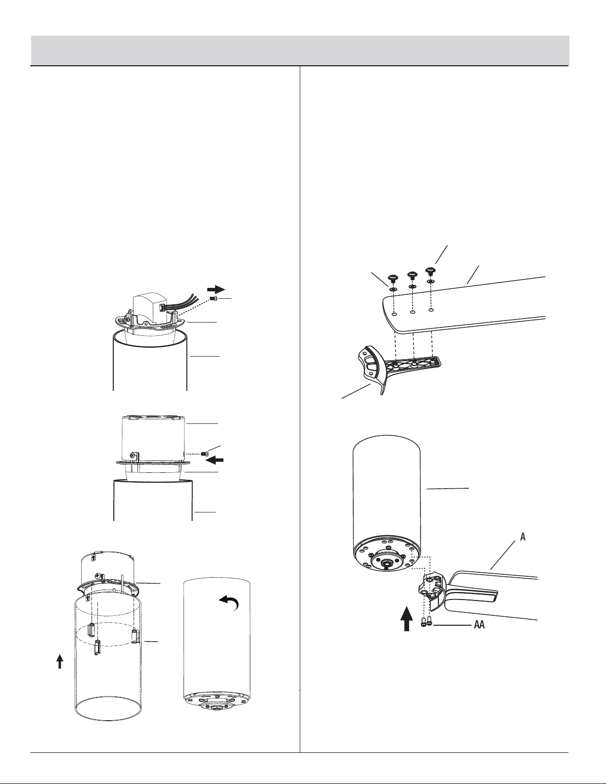
□
Remove one of the three mounting screws (EE) on the motor
assembly and loosen the other two (Do not remove). Align the key
holes on the mounting plate (D) with the mounting screws (EE) heads
from the top of the motor assembly (C). Then, rotate the motor
assembly(C) until both screws engage into the notches on the key
holes. Tingten the two mounting screws (EE).
Finally, reinstall the single mounting screws (EE) removed previously
and tighten to secure the motor assembly (C).
Slide the motor housing (
F)
until the screws align with the
slots on the motor assembly (
C)
. Rotate themotor housing (
C)
until thescrew heads align with the notches on the motor
housing (
F)
.
Assembly -Hanging the Fan/
Attaching the Fan Blades
□
5
8
□
Fastening the blade assemblies
to the fan motor assembly
□
Attach the fan blades (A) to the blade holders (B) by
using three blade screws (BB) and fiber washers (CC).
Tighten screws (BB) and fiber washers (CC) securely.
Remove the preassembled blade holder screws (AA),
and fasten blade assemblies to the fan motor assembly (C)
one by one.
C
F
4Attaching the Fan Motor Assembly
and Motor Housing
BB
CC
A
B
F
F
C
EE
F
C
D
EE
X10
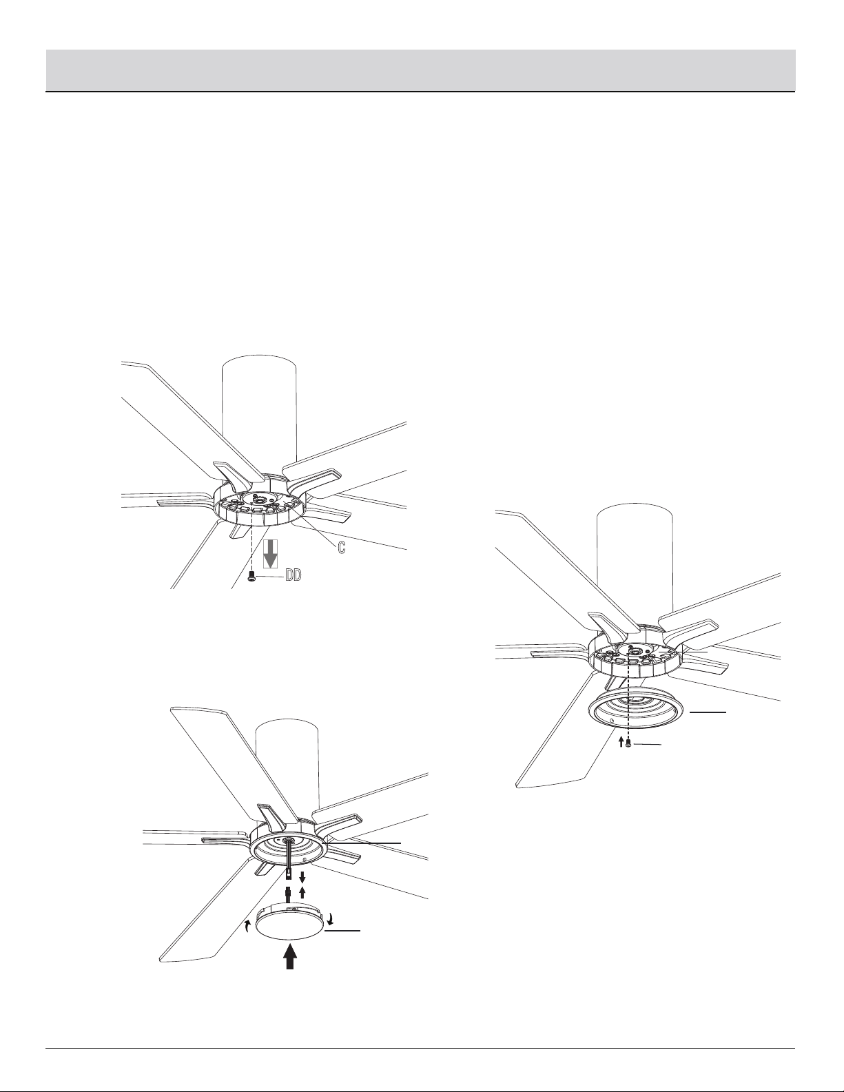
Align the key holes on the light kit plate (E) with the light kit screws (DD) on the motor assembly (C). Rotate the light kit plate (E)
until the notches align with the screw heads and tighten the screws.
Finally, reinstall the single light kit screws (DD) removed previously and tighten to secure the motor assembly (C).
Connect the lightlead wire.
Place the
Light kit assembly(G)
into the light kit plate (E), aligning the three flat areas on the top flange of
the
Light kit assembly(G)
with the raised dimples in the light kit plate (E).
Fastening the light kit plate and light kit assembly to the fan motor assembly
Assembly - Installing the Light Kit
Remove one of three light kit screws (DD) on the motor assembly (C). Loosen the other two screws.
(Do not remove)
□
□
□
6
9
E
DD
C
G
E
H
□
Turn the Light kit assembly(G)
clockwise until it stops.
DD

10
H
REMOTE CONTROL OPERATING INSTRUCTIONS
LEARNING PROCESS
Operation
WARNING : Do not short-circuit, disassemble, heat up,
connect improperly, or dispose of used batteries in fire. Do
not recharge or mix batteries with used or other battery
types. Immediately remove used batteries.
WARNING: a)The cells shall be disposed of properly,
including keeping them away from children; and
b) Even used cells may cause injury.
NOTE:After the AC power is on, do not press any other button
on the remote control before pressing the (FAN ON/OFF)
button. Doing so will cause the procedure to fail.
Install a 12V battery (J) into the remote control (H). Fasten the battery
cover screw (HH) after installation. To prevent damage to the remote
control, remove the battery if not used for long periods of time.
WARNING: Chemical Burn Hazard. Keep batteries away
from children. This product contains a lithium button/coin
cell battery. If a new or used lithium button/coin cell battery
is swallowed or enters the body, it can cause severe
internal burns and can lead to death in as little as 2 hours.
Always completely secure the battery compartment. If the
battery compartment does not close securely, stop using the
product, remove the batteries, and keep it away from
children. If you think batteries might have been swallowed
or placed inside any part of the body, seek immediate
medical attention.
NOTE: After turning the AC power back on, do not press any
other button on the remote control before pressing the
button. Doing so will cause the learning procedure to fail
and the power to the fan will have to be turned off again to
start over.
Turn main power to fan back on and within 30 seconds
press and hold the button on the remote for 5 seconds
to sync the transmitter to the fan.
Once the fan has detected the remote, the light on the fan
will blink twice to indicate your fan is now ready to use.
Fans without light-kits have no indicator but will be ready to
use after holding the button for the 5 seconds.
HH
J
H

11
1. Fan button.-Press and release the button to turn the fan on or off.
Fan off. The fan memory function will store the current setting for the
next time the fan is in use.
2. 1,2,3,4,5,6 buttons:
3. Light functions
Press and release button one time will turn the light on or off.
Press to increase the desired light level.
Press to decrease the desired light level.
4. Fan reverse button (Must be Pushed when the fan isin operation)
(Counterclockwise Direction) A downward air flow creates a
cooling effect. This allows you to set your air conditioner on a
higher setting without affecting your comfort.
(Clockwise Direction) An upward air flow moves warm air off the
ceiling. This allows you to set your heating unit on a lower setting
without affecting your comfort.
NOTE: On start up your ceiling fan will oscillate back and forth. This is NORMAL
OPERATION for DC ceiling fan as it goes through its calibration cycle. The fan is
NOT DEFECTIVE.
H
Operation (continued)
These six buttons are used to set the fan sped as follows:
1=low speed 2=medium low speed
3=medium speed 4=medium high speed
5=high speed 6=Extra high speed
12
Operation (continued)
Care and Cleaning
□Check the support connections, brackets, and blade
attachments twice a year. Ensure they are secure.
Because of the fan’s natural movement, some
connections may become loose over time. It is not
necessary to remove the fan from the ceiling.
□Clean your fan periodically. Use only a soft brush or
lint-free cloth to avoid scratching the finish. The plating is
sealed with a lacquer to minimize discoloration or
tarnishing.
□(Optional) Apply a light coat of furniture polish to the wood
blades.
□(Optional) Cover small scratches with a light application of
shoe polish.
Do
□Do not use water when cleaning. Water could damage the
motor, or the wood, or possibly cause an electrical shock.
□Do not apply oil to your fan or motor. The motor has
permanently-lubricated sealed ball bearings.
Do not
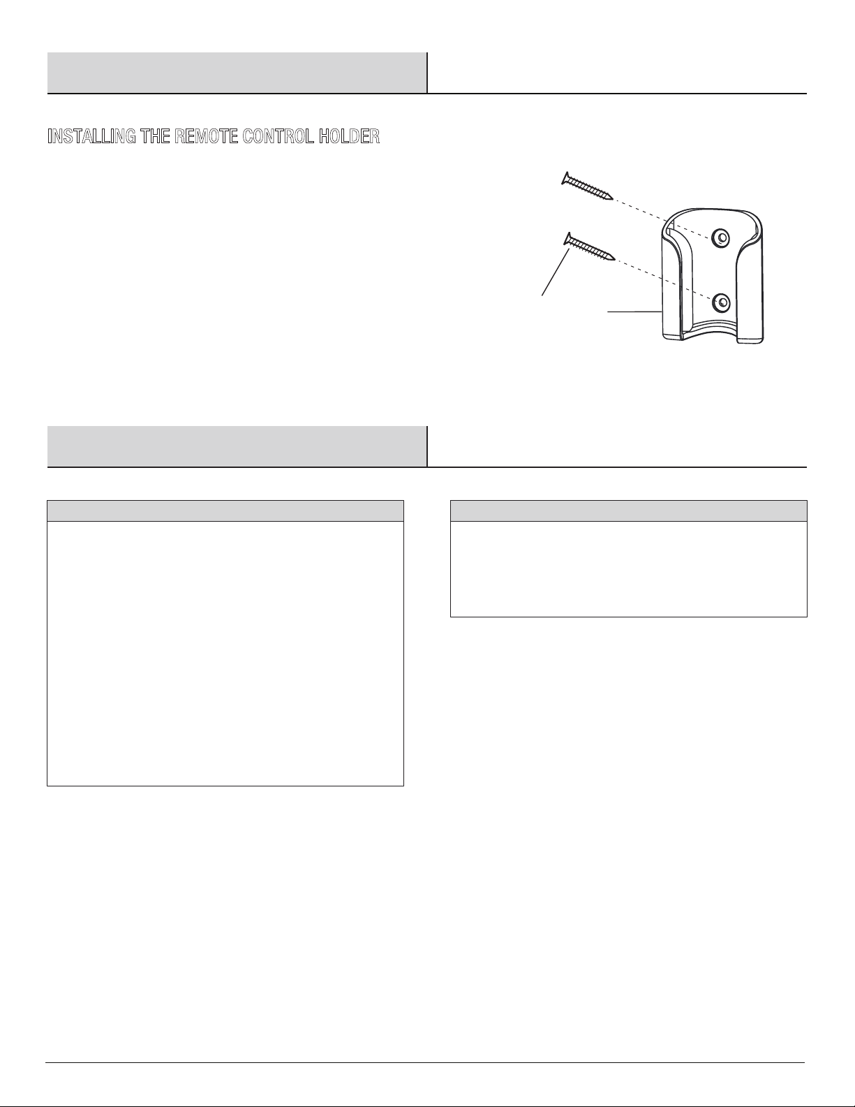
INSTALLING THE REMOTE CONTROL HOLDER
□Attach the remote control holder ( I ) with the two remote control
holder mounting screws (GG).
GG I

13
17
Troubleshooting
WARNING: Ensure the power is off at the electrical
panel box before you attempt any repairs. Refer to the section
“Making the Electrical Connections” on page 9.
□Do not connect the fan with wall mounted variable speed control(s).
□Check the battery in the remote control.
□Check that all blade and blade arm screws are secure.
□Most fan wobble problems are caused when blade levels are unequal. Check this level by selecting a
point on the ceiling above the tip of one of the blades. Measure from a point on the center of each blade
to the point on the ceiling. Rotate the fan until the next blade is positioned for measurement. Repeat for
each blade. Measurements deviation should be within 1/8 in. Run the fan for 10 minutes.
The fan wobbles.
The remote control is
not working.
Problem Solution
□Ensure you are in the normal range of 10-20 feet.
□Make sure the receiver has been matched.
□Check main and branch circuit fuses or breakers.
□Check line wire connections to the fan and switch wire connections in the switch housing.
□
□Make sure all motor housing screws are snug.
□Make sure the screws that attach the fan blade arm to the motor hub are tight.
□Make sure wire nut connections are not rattling against each other or the interior wall of the switch
housing.
□Allow a 24-hour "breaking-in" period. Most noises associated with a new fan disappear during this
time.
□If using the ceiling light kit, make sure the screws securing the glassware are tight. Check that the light
bulb is also secure.
□Make sure there is a short distance from the ceiling to the canopy. It should not touch the ceiling.
□Make sure your ceiling box is secure and rubber isolator pads are used between the mounting bracket
and outlet box.
The fan will not start.
The fan sounds noisy.
17
□This is normal start-up procedure for DC motor fans. The partial movement during start-up is the result
of the DC motor aligning the internal magnetic poles for proper motor operation. This design saves
electricity and allows the fan to operate much quieter than standard AC motor fans.
Fan moves backwards
and forwards when
turned on.
Reset the transmitter by going through the transmitter “LEARNING PROCESS”.
This equipment has been tested and found to comply with the limits for a Class B digital device, pursuant to Part 15 of the FCC Rules.
These limits are designed to provide reasonable protection against harmful interference in a residential installation. This equipment
generates uses and can radiate radio frequency energy and, if not installed and used in accordance with the instructions, may cause
harmful interference to radio communications. However, there is no guarantee that interference will not occur in a particular installation.
If this equipment does cause harmful interference to radio or television reception, which can be determined by turning the equipment
off and on, the user is encouraged to try to correct the interference by one or more of the following measures:
• Reorient or relocate the receiving antenna.
• Increase the separation between the equipment and receiver.
• Connect the equipment into an outlet on a circuit different from that to which the receiver is connected.
• Consult the dealer or an experienced radio/TV technician for help.
CAUTION:
This device complies with Part 15 of the FCC Rules. Operation is subject to the following two conditions:
(1) This device may not cause harmful interference, and
(2) this device must accept any interfe
14
FCC Statement
The following responsible party designated in FCC §2.909 is responsible for this declaration:
Model Number: BF9775L52-WH/BF9775L52-WH/BF9775L52-WH
Company Name:Breezism LLC
Company Address: 1579, S Bellaire St, Denver, CO, 80222, US
Telephone Number:1-303-500-8801
rence received, including interference that may cause undesired operation.
equipment.

BREEZISM
This manual suits for next models
2
Table of contents
Other BREEZISM Fan manuals

Popular Fan manuals by other brands


Delta
Delta breez Smart SMT150-200 Installation and operating instructions

ProKlima
ProKlima TFN-111449.2 instruction manual

Ebmpapst
Ebmpapst W3G350-CG03-30 operating instructions

Kambrook
Kambrook KFA839 Nstructions booklet

Xpelair
Xpelair XHR150PC installation instructions

MSW Motor Technics
MSW Motor Technics MSW-FFF-01 user manual