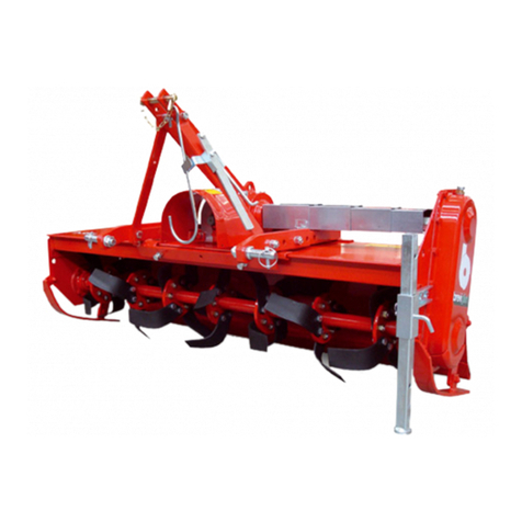
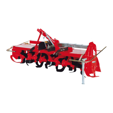
breviglieri DOBLE Operating instructions

Manuale d’uso e manutenzione “Istruzioni Originali”
Prima di iniziare ad operare, leggere attentamente le istruzioni per l’uso
Conservare il presente manuale per futura consultazione
Operating and Maintenance Manual “Original Instructions”
Read these operating instructions carefully before using the machine
Keep this manual for future reference
Manuel d’utilisation et d’entretien “Instructions Originales”
Avant de commencer le travail, lisez attentivement les consignes d’utilisation
Conservez ce manuel pour référence future
Instrucciones de empleo y mantenimiento “Instrucciones Originales”
Antes de empezar a operar con la máquina , leer atentamente las instrucciones para el empleo
Mantenga esto manual como referencia futura
Betriebs- und Wartungsanleitung “Originalbetriebsanleitung”
Bevor Sie mit der Arbeit beginnen, lesen Sie diese Betriebsanleitungen aufmerksam durch
Bewahren Sie dieses Handbuch zum Nachschlagen
eseiD - eirés ed orémun ud ritrap à elbalav tse leunam eC - rebmun laires morf dilav si launam sihT - alocirtam allad odilav è elaunam otseuQ
Handbuch ist gültig ab Seriennummer - Este manual es válido a partir del número de serie ..................................................... 2015Z0200054
Codice documento - Document code - Code du document - Dokument
Ref. - Signatura del documento ...................................... Z0200060
Revisione n°/in data - Review #/Date - Révision n°/Date - Überprüfung
Nr./am - Revisión No./fecha.................................... 08 / 25.05.2015

- 20 -
doble - maxi doble
1.1 INTRODUCTION ...................................................................20
1.2 WARRANTY ..........................................................................20
1.2.1 WARRANTY EXCLUSIONS ......................................................21
1.3 DESCRIPTION OF THE MACHINE ..........................................21
1.3.1 DESCRIPTION........................................................................22
1.3.2 USE .......................................................................................22
1.4 IDENTIFICATION ...................................................................23
1.5 NOISE LEVEL .........................................................................23
1.6 TECHNICAL SPECIFICATIONS ................................................23
2.1 SAFETY NOTES ......................................................................23
2.2 SAFETY DECALS ....................................................................24
2.3 SAFETY AND ACCIDENT PREVENTING RULES .......................24
3.1 TRANSPORT AND HANDLING ...............................................26
4.1 BEFORE USE ........................................................................27
4.1.1 DRIVELINE ............................................................................27
Description and Main features
1.1 INTRODUCTION
This manual contains all the information and indications considered necessary to know, correctly use and normally service doble
rotary tiller (also called machine in the text) manufactured by BREVIGLIERI SpA of Nogara (VR) Italy, also
called Manufacturer in the text. The information and indications do not give a full description of the various components or a
detailed illustration of how they operate. However, the user will everything he normally requires in order to safely use the
machine and keep it in a serviceable condition. Failure to comply with the indications given in this manual, negligence during
work, incorrect use of
The Manufacturer therefore declines all and every liability for damage due to negligence and failure to comply with the
instructions in this manual.
If repairs or overhauls of a complex nature are required, contact an authorized assistance center with specialized personnel or the
actual Manufacturer who is at your complete disposal for prompt and accurate technical assistance and anything else that can
This manual must be kept in a safe place, ready to hand for consultation throughout the entire life of the machine. Reference will
solely be made to the Italian version of the instructions in the event of disputes.
Some of the illustrations in the manual may not exactly depict the machine in your possession: they are included for the sole
purpose of explaining the operations that must be carried out.
1.2 WARRANTY
The Manufacturer guarantees brand new products for a period of 12 (twelve) months from the date of delivery. When the machine
is delivered, make sure that both it and the accessories are complete and in a perfect condition. Complaints should be presented
in writing within 8 (eight) days from receipt of the machine. The warranty merely covers the repair or replacement, free of charge,
of those parts which, after thorough examination by the Manufacturer, are recognized as being defective (with the exclusion of
tines). Expenses concerning replacement of lubricants, transport costs, customs duties and VAT remain at the purchaser’s charge
in any case. Replacement or repair of parts under guarantee shall in no case extend the warranty terms.
The Manufacturer will not accept returned goods without prior written authorization.
The purchaser shall only be able to exercise his rights in relation to the warranty when he has complied with the conditions gover-
ning warranty performance, as indicated in the supply contract.
4.1.2 DRIVELINE WITH ADJUSTABLE PLATE CLUTCH .....................28
4.1.3 DRIVELINE WITH AUTOMATIC CLUTCH ................................28
4.1.4 SIDE DRIVELINES ..................................................................28
4.2 WORK POSITION ................................................................28
4.3 HITCHING TO THE TRACTOR ................................................29
4.4 TRANSPORT POSITION ...............................................29
4.5 HYDRAULIC CIRCUIT .............................................................30
4.6 HOEING UNIT OPENING/CLOSING .......................................30
4.6.1 WORK DEPTH ADJUSTMENT ................................................31
4.6.2 HITCHING/UNHITCHING THE HOEING UNITS .......................31
4.7 DURING WORK .....................................................................31
4.7.1 USEFUL TIPS .........................................................................32
4.8 TOOLS...................................................................................32
4.9 STOPPING THE MACHINE .....................................................33
4.9.1 PARKING ...............................................................................33
4.9.2 ELIMINATING OF THE MACHINE ..........................................34
5.1 ROUTINE MAINTENANCE ....................................................34
5.2 LUBRICATION .......................................................................35
5.2.1 RECOMMENDED LUBRICANTS .............................................35
5.2.2 AFTER THE FIRST 8 HOURS SERVICE ....................................35
5.2.3 EVERY 20 HOURS SERVICE....................................................35
5.2.4 EVERY 100 HOURS SERVICE..................................................35
5.2.5 EVERY 500 HOURS SERVICE..................................................35
5.3 PREPARING FOR STORAGE ..................................................35
5.4 SPARE PARTS .......................................................................36
and maxi doble

doble - maxi doble
- 21 -
1.2.1 WARRANTY EXCLUSIONS
(Besides the circumstances indicated in the supply contract) the warranty becomes void:
When, following repairs made by the user without the Manufacturer’s consent or owing to the installation of spurious spare
-
o-
val of the safety devices with which the machine is equipped shall automatically void the warranty and relieve the Manufac-
Even when covered by the warranty, the machine must be returned Carriage Free
1.3 DESCRIPTION OF THE MACHINE
doble and maxi doble rotary tiller bears «CE» marking in compliance with the European Union standards described in directive
2006/42/EC
Fig. 1
Central bearing frame with three-point hitch
Upper 3-point hitch
Connection point to lift the machine
Lower 3-point hitch
Main driveline support
Central transmission unit
PTO to engage main driveline
Lh upper steerage hoe frame
Side gearbox transmission
Side driveline
Hydraulic cylinder for harrow opening/closing (2 pcs)
Hoe blade rotors
Bonnet adjuster screw
Hydraulic circuit pipes
Safety guards
Hydraulic cylinder to adjust the tilling depth
Tine rotor with spinning phase

- 22 -
doble - maxi doble
DIMENSIONS
1.3.1 DESCRIPTION
doble and maxi doble steerage hoe consists of a central bearing framework (1 Fig. 1) with three-point hitch, which couples to
hoeing units at the sides. These can be folded upwards and closed, thus allowing the entire machine to be transported on
roads (if the machine is enabled to do this by the Highway Code in force in the country of use) or along particularly narrow places.
This on allows the machine to work large areas. With the hoeing units operating, the machine measures 142 - 157 - 181 - 197
220 - 249 inches in width, depending on the model. The two side hoeing units are lifted and folded hydraulically, by means of the
control on the tractor. The machine will only operate when hitched to a tractor of adequate power (see technical for
the power rating required). To operate the machine, drive is transmitted from the tractor by means of the driveline (with
CE marking) which meshes with the central transmission unit (7 Fig. 1), and is distributed between the two side transmissions (11
Fig. 1) which operate the respective hoe blade rotors by means of a side geared transmission unit.
1.3.2 USE
has solely been designed for use in agriculture in order to work and break up the soil. One single operator
seated on the tractor is able to carry out the various tillage operations. Any other use of the machine from the expla-
nations given in this manual relieves for Manufacturer from all and every liability for deriving damage to persons, animals or
property.
Fig.2
Model A* B* C*
doble - 360 159 142 80
doble - 400 175 157 88
maxi doble - 460 199 181 100
maxi doble - 500 215 197 107
maxi doble - 630 267 249 133
maxi doble - 560 238 220 119
two
doble and maxi doble

doble - maxi doble
- 23 -
1.4 IDENTIFICATION
4 Fig. 1
«CE» marking
Manufacturer’s name and address
B) Machine version
E) Year of manufacture
The data on the of the machine copied into the page of this and must stated
when spare parts and/or assistance are required.
1.5 NOISE LEVEL
.................................................................................................................................... dB 82
.......................................................................................................................................... dB 98
CAUTION
1.6 TECHNICAL SPECIFICATIONS
Mod. Working
width
Weight Power requirement N° cutting
tools
Hood RG Ø450 RP Ø500
General safety regulations
2.1 SAFETY NOTES
The user must inform his the risks deriving from the devices to safeguard the
operator and out the gen accident-preventing tions est shed the Directives and the s in force in the countr
where the machine is used. It is therefore for operators to read this the and
The to with the
in. lbs CV kW knives
doble - 360 142 4564 5225 5688 150 - 220 110 - 162 84
doble - 400 157 4806 5600 6173 180 - 220 132 - 162 96
maxi doble - 460 181 5291 5908 6371 200 - 400 147 - 294 108
maxi doble - 500 197 5467 6261 6768 220 - 400 162 - 294 120
maxi doble - 560 220 5732 6724 7363 240 - 400 176 - 294 132
maxi doble - 630 249 6129 7253 8554 260 - 400 191 - 294 156

- 24 -
doble - maxi doble
There are three danger levels:
DANGER: This is the maximum level danger signal and warns that unless the described operations are carried out
correctly, they will cause serious injuries, death or long term health hazards.
WARNING: The «WARNING» signal warns that unless the described operations are carried out correctly, they could cause
serious injuries, death or long term health hazards.
CAUTION: This sign warns that unless the described operations are carried out correctly, they could cause damage to the
machine and/or persons.
2.2 SAFETY DECALS
The machine has been designed and built in compliance with all possible safety standards able to safeguard those who work with
it. Despite this, there may still be residue hazards which are signalled on the machine by decals. These decals (pictograms) are
Keep the decals clean and immediately replace them if they detach or become damaged.
Carefully read the following descriptions and memorize the meanings of the safety decals.
Danger of
lower limbs
being cut
Keep
at a safety
distance
from the
machine.
Sharp
objects
could be
thrown
up by the
machine.
Keep at
a safety
distance.
Before
proceeding with
maintenance
operations, stop
the machine, lower
it to the ground
and consult the
instruction manual.
Hitching
points
to lift the
machine.
Carefully
read the
instruction
manual
before
beginning
work.
Danger of
upper limbs
Do not remove
the guards and
keep well away
from moving
parts.
Danger of
being caught
up by the
driveline.
It is absolutely
forbidden to
get near the
driveline when it
is operating.
Danger of
falling.
It is absolutely
forbidden to
climb on to the
machine.
Personal
protective
equipment
to safeguard
against noise.
2.3 SAFETY AND ACCIDENT PREVENTING RULES
Carefully read the safety and accident-prevention rules before using the machine. Consult the Manufacturer if in doubt. The Ma-
nufacturer declines all and every liability for failure to comply with the safety and prevention regulations described below.
Do not touch moving parts.
It is absolutely forbidden to transport persons or animals on the machine.
It is absolutely forbidden to operate the tractor or have it operated, with the machine hitched, by persons who are not in
possession of an adequate driving license, by inexpert persons or by those whose psycho-physical conditions of health are
not good.
Comply with all the accident prevention measures recommended and described in this manual.
Danger of being crushed
during the opening/
closing phase. Do not get
between the two parts of
the machine.
Pipes containing
pressure. Take
care since
oil may spurt out
if a pipe breaks.

doble - maxi doble
- 25 -
add ballast at the front of the tractor in order to balance the weight on the axles.
chains. Keep well away from the spinning driveline.
Before starting the tractor and machine, make sure that all the safety devices for transportation and use are in perfect
conditions.
Comply with the Highway Code regulations in force in your country when travelling on public roads.
Do not exceed the maximum tolerated weight on the tractor axles.
Become familiar with the controls and their functions before beginning work.
Wear suitable clothing.
protective garments such as goggles, gloves and protective footwear if required in the country where the machine is used
or when working on particular stony ground.
The machine must be hitched to a tractor with an adequate power rating.
Pay the utmost attention when hitching and unhitching the machine to and from the tractor.
Any accessories used for transportation purposes must be equipped with adequate signs and guards.
Never ever leave the driver’s seat whilst the tractor is operating.
When driving round bends with and without the machine, take care of the centrifugal force exercised when the center of
It is absolutely forbidden to linger within the range of action of the machine when this is operating.
brake and remove the ignition key from the control panel.
It is absolutely forbidden to get between the tractor and machine while the engine is running and the driveline engaged.
Move the power lift control lever to the locked position before you hitch or unhitch the machine to or from the three-point
linkage.
The class of the machine’s coupling pins must correspond to that of the power lift hitch.
Take great care when you work near the lift links. This is a very dangerous area.
It is absolutely forbidden to get between the tractor and the machine hitch in order to manoeuvre the lifting command
from the outside.
Fix the side lifting links with the relative chains and idlers during the transport phase.
Set the control lever of the tractor’s hydraulic lifting control in the locked position when driving on the roads with the ma-
chine raised.
Only use the driveline recommended by the Manufacturer, with «CE» marking.
Pay the utmost attention to the driveline guard, both during transport and
work.
The driveline must always be assembled and disassembled when the tractor
Make sure that the driveline is assembled on the tractor and machine PTO in
the correct way.
Prevent the shields from turning by means of the relative chains and always
read the operation and maintenance manual supplied with the driveline.
Make sure that there are no bystanders or animals in the vicinity before you engage the PTO.
3) and when it is
not used.
-
tion key removed from the tractor’s ignition switch.
Rest the driveline on its stand ( 6 Fig. 1) when not used.
Prolonged use of the machine can cause the overdrive housing ( 7 Fig. 1) and certain parts of the hydraulic circuit to overhe-
at. Do not touch these parts during and immediately after using the machine since they could cause burns.
Periodically check to make sure that the nuts and bolts are well torqued. Tighten them if necessary.
Place adequate supports under the machine as a precaution when servicing or replacing the tines/blades with the machine
raised.
that the tines are at a standstill.
Use the recommended oils.
Spare parts must comply with the requirements established by the Manufacturer. Only use genuine spare parts.
The safety decals must always be clearly visible. They must be kept clean and replaced if they become illegible (new ones
can be obtained from the Manufacturer).
The instruction manual must be kept throughout the life of the machine.
If the country in which the machine is used has noise prevention laws, adapt to these provisions by using the appropriate
Fig.3

- 26 -
doble - maxi doble
protections. The measured noise levels are given in section «1.5 Noise level».
Comply with the laws in force in the country where the machine is used when it comes to using and disposing of the pro-
ducts used to clean and service the machine. Also comply with the instructions given by the manufacturer of such products.
Comply with the anti-pollution laws in force in the country of use if the machine must be scrapped.
Transport and handling
3.1 TRANSPORT AND HANDLING
CAUTION
If the machine, hitched to the tractor, must circulate on the public roads, comply with the Highway Code regulations in
force in the country in which the machine itself is used.
The machine must be raised at least 40 cm from the ground for road transport.
If the machine must be transported over a long distance, it can be loaded on a truck or railway car. In this case, consult «1.6 Tech-
» for the weight and dimensions. This will allow you to make sure that the machine can pass through tunnels
or low constructions without To lift the machine from the ground to the loading platform, use a crane with an adequate
carrying capacity and hook up the machine from the relative lifting points indicated on the machine.
Loading with a crane: make sure that the carrying capacity of the crane is to lift the weight of the machine. The connecting
points for lifting are clearly visible and are marked by stickers. Lift the machine with the utmost care and move it slowly without
jolting on to the truck or railway car.
DANGER
The lifting and transporting operations can be very dangerous unless they are carried out with the greatest care: have
all persons not directly involved in the lifting operations move well clear of the lifting area. Clear and delimit the zone to
hanging loads and always keep at a safety distance from them. When transported, the loads must not be lifted more than
20 centimeters from the ground. Also make sure that the zone in which the operations take place is uncluttered and that
fall.
CAUTION
The surface on to which the machine is to be loaded must be perfectly horizontal, to prevent the load from shifting.
Once the machine has been moved on to the truck or wagon, make sure that it remains blocked in position.
-
cal, using well tightened ropes or chains suited to its weight and able to prevent it from moving in any way.
After having transported the machine to the desired site and before removing the elements that hold it in place, make sure
that its position is unable to be of danger.
Now remove the ropes and unload the machine from the means of transport in the same way as it was loaded.

doble - maxi doble
- 27 -
Instructions for use
4.1 BEFORE USE
WARNING
Before he sets the machine at work, the operator must have read and understood all parts of this manual and particularly
«Section 2» about safety.
Before beginning work, make sure that the machine is in order, that the lubricating oils are at the right level and that all parts
DANGER
and blocked.
4.1.1 DRIVELINE
DANGER
The driveline is a mechanical component. When it is operating it can be a source of danger to the physical well-being of
those who work with it. Take the greatest care when carrying out operations that involve the driveline. Carefully read the
instruction manual supplied with the driveline. If you have doubts about the way it operates, if it is without its shields, worn
or broken, replace it with a new driveline that possesses the same characteristics and bears the «CE» mark.
DANGER
Never modify or adapt the driveline in any way.
If the length must be adapted, work with the utmost care so as to keep the telescopic tubes coupled to the maximum extent.
With the exception of length adaptation, it is forbidden to modify the driveline. If this is necessary, contact the Manufacturer.
Take the greatest care when inserting the driveline. Make sure that it is well locked on
both the tractor’s PTO and on the machine. Also comply with the indications in the
instruction manual supplied with each driveline. Make sure that the driveline shield,
fastened with the relative chains, is free to turn without obstruction. Also check the
guards on both the tractor and implement. If they are not in a perfect condition,
they must be immediately replaced with new protections. It is very important for the
protective guards to overlap the driveline shields by at least 5 cm on both sides.
When the driveline is fully extended, in all work conditions, the telescopic tubes must
overlap to at least 1/3rd of their length (A 4
When the driveline is fully inserted, the play must be at least 4 cm (B 4 Contact
CAUTION
Before engaging the PTO, make sure that its rotation speed corresponds to the rate for which the machine has been desi-
gned.
Fig. 4

- 28 -
doble - maxi doble
4.1.2 DRIVELINE WITH ADJUSTABLE PLATE CLUTCH
The driveline has a safety clutch to protect the transmission components of the machine against stress and excessive overloads.
The clutch is calibrated for medium-duty use. If it slips during work, all the nuts that hold the springs must be evenly tightened by
half a turn and the operation of the device checked after about 200 meters of work. Repeat the operation if necessary. The clutch
must be adjusted by unscrewing the nuts if it is blocked.
CAUTION
If the clutch still slips even when all the nuts have been tightened, the friction plates must be changed as they could be worn
or because the springs have become slack. Never fully tighten the nuts as this eliminates the function of the springs and
clutch itself, to the detriment of the transmission components.
4.1.3 DRIVELINE WITH AUTOMATIC CLUTCH
On request, the Manufacturer can supply a driveline complete with automatic clutch calibrated for a medium-duty load. This
clutch cannot be adjusted. In the event of an overload, the clutch slips and continues to operate as soon as the obstruction has
been passed, without external intervention. Any clutch servicing operations must be carried out in the workshop in compliance
with the driveline manufacturer’s instructions.
CAUTION
Do not allow the machine to operate unless it digs into the soil. When working, do not drive around bends with the machine
in the soil. Do not work in reverse. Always raise the implement before you change direction or reverse. During transport or
whenever the machine must be lifted, remember to adjust the power lift of the tractor so that the steerage hoe is not raised
more than about 16 in. from the ground. Do not drive on the public roads with the machine caked with soil, grass or other
materials that could dirty the road surface or hamper the in any way. Do not allow the machine to drop violently on
to the ground. Lower it slowly to allow the tines to gradually penetrate into the soil otherwise all the machine components
would be subjected to stress that could lead to breakages.
4.1.4 SIDE DRIVELINES
The two side drivelines (7 Fig. 1) transmit drive from the reduction housing (central transmission
drives (4 Fig. 1). The standard marked «CE» with relative guards and chains. If these drivelines are da-
CAUTION
If the side drivelines (14 Fig. 1) are removed, it is very important to ensure that they are remounted in the same position
(Fig. 6), i.e. the fork of the left driveline must be positioned at the same angle as the right one, otherwise the transmission
unit could be damaged.
4.2 WORK POSITION
DANGER
The operator must be seated in the driving seat of the tractor when the machine is working since only from that position is
he able to act correctly. Before he leaves the driving seat, the operator must stop the machine, apply the parking brake and

doble - maxi doble
- 29 -
4.3 HITCHING TO THE TRACTOR
DANGER
Hitching to the tractor could be a dangerous operation. Take great care and strictly comply with the instructions.
Proceed in the following way to hitch the machine to the tractor in the correct way:
Make sure that there are no objects, bystanders and/or animals in the immediate vicinity of the machine and that the PTO
6
1
4.4 TRANSPORT POSITION
5):
M x s < 0,2T x i + Z(d+i)
M < 0,3T
Z > {[(M x s) – (0,2T x i)] / (d x i)} .....
where:
i = tractor’s wheelbase
d =
s =
T = weight of the tractor in running order
Z = ballast weight
M = weight of the machine
Fig. 5

- 30 -
doble - maxi doble
4.5 HYDRAULIC CIRCUIT
degagne dna rotcart eht fo stniop eerht eht ot dehctih .e.i ,yaw tcerroc eht ni snoitarepo yranimilerp eht tuo deirrac gnivah retfA
eht wolla ot redro ni rotcart eht no spat ciluardyh evitaler eht ot detcennoc eb tsum tiucric ciluardyh eht fo sepip eht ,enilevird eht
various components of the implement to operate.
KEY Fig.12
MAXIMUM PRESSURE 180 Bar
1/4” AND 3/8” HYDRAULIC PIPES
A) Hydraulic cylinders to control steerage hoe
B) Hydraulic cylinders to regulate rollers
C) Hydraulic cylinder to hitch/unhitch steerage hoe
D) Control cylinder speed adjuster valve
E) Floating valve
F) Flow divider
G) Sequence valve
H) Safety valve
I ) Locking valve
1) Harrow closing/harrow hitching oil pipe
2) Harrow opening/harrow unhitching oil pipe
3) Roller lowering oil pipe
4) Roller lifting pipe
4.6 HOEING UNIT OPENING/CLOSING
The two hoeing units are respectively opened during the work phase and closed when the machine is transported on the roads
by a hydraulic control with two cylinders (16 Fig. 1 and 4 Fig. 8). Both hydraulic cylinders are equipped with locking valves (17 Fig.
1). If a hydraulic pipe suddenly bursts, these valves instantly stop the oil and, consequently, the machine in the position to
which it has set. The cylinders also have a valve that regulates the opening and closing speeds of the hoeing units (D Fig. 12).
These valves are calibrated so that the movement of the cylinders and, thus, the lowering and lifting movements of the hoeing
tun reniater eht gninesool ro gninethgit yb deidom eb nac tnemevom sihT .elbissop sa suoenegomoh dna htooms sa era ,stinu
of the governor valve until the two side hoeing units lift and lower in the desired way. After this, lock the valve in position
with the ring nut in the governor valve.
WARNING
When the hoeing units are in the vertical position, check the rear visibility from the driving seat in the tractor as it could be
obstructed with the hoeing units in this condition. In this case, you are advised to mount one or more rear view mirrors on
the tractor in order to ensure unobstructed visibility.

doble - maxi doble
- 31 -
DANGER
Whenever the two hoeing units are positioned vertically, make sure that they are automatically locked in place with the
two locking hooks
4.6.1 WORK DEPTH ADJUSTMENT
The work depth of the folding steerage hoe can be regulated, depending on the version:
with hydraulically controlled cylinders ( 20 Fig. 1).
Raise the roller to dig deeper into the soil. Lower the roller if the work depth must be more shallow. Work depth adjustment with
the hydraulically controlled cylinders is carried out from the driving position by means of a hydraulic actuator that controls the two
hydraulic cylinders (20 Fig. 1). These cylinders regulate the rear rollers (19 Fig. 1) and therefore determine the work depth. Both
hydraulic cylinders have a balancing valve that allows the rollers and, thus, the work depth to be regulated to the same extent.
4.6.2 HITCHING/UNHITCHING THE HOEING UNITS
The hydraulic circuit of the machine allows the two hoeing units to be hitched and unhitched in an automatically sequential way by
means of a control in the tractor, by moving the two hooks used for road transport. After each command, always check to make
sure that the system has coupled or released correctly.
4.7 DURING WORK
Proceed in the following way after you have correctly hitched the machine, sat down in the driver’s seat of the tractor and started
the tractor engine:
Raise the machine about 10 cm from the ground so that the rotor does not touch the vegetation that needs to be cut
Run the engine at a low rate and engage the PTO
Gradually accelerate until the PTO is operating at full rate
Engage the forward gear and start work with the PTO at full rate
Gradually lower the machine until it rests on the ground. This allows it to adapt to the contours of the soil.
CAUTION
Do not depress the accelerator pedal in an imprudent way with the PTO engaged.
To break up the soil to the required degree, you must consider several factors, ex:
The nature of the soil (medium consistency, sandy, clayey etc.)
The working depth
The ground speed of the tractor
Optimum machine adjustment
For a better soil levelling and crumbling, the rotary tiller is equipped with a rear hood, with adjustable opening by means of a
locking chain and on request by means of a spring rod.
WARNING
Adjust the hook by keeping it as opened as possible to obtain a better levelling thus avoiding dangerous throwing of the
clods and stones as well as the hood itself
CAUTION
A better soil crumbling can be obtained with a low tractor ground speed, the rear bar lowered and the blade-holder rotor spinning at
200 rpm. Besides holding back the clods already broken up by the blades, the rear bar also gives a well-levelled and uniform surface

- 32 -
doble - maxi doble
after the soil has been worked. When the rear bar is raised, the clods are no longer broken up and the soil is no longer levelled.
4.7.1 USEFUL TIPS
Here are a few useful suggestions on how to resolve some of the problems that may occur during work.
Cut plants shredded to much
Slightly lift the cutter from the ground, adjusting the height with the wheels (the blades of the cutter must not touch the
ground).
Increase the ground speed.
Cut plants not shredded enough
Slightly lower the machine towards the ground.
Reduce the ground speed.
Do not work in soil that is too wet.
Rotor clogged
Soil too wet to work.
Raise the machine from the ground.
Reduce the ground speed.
Do not work where the grass is too tall. If necessary, remove any material that has built up at the sides of the rotor to pre-
vent overheating.
The machine jolts over the ground or vibrates
Foreign bodies locked between the knives.
Knives incorrectly mounted without the helical arrangement or with edges that dig into the ground.
Worn or broken knives.
Rotor misshapen owing to blows received during work from foreign bodies in the central part.
Other faults
The machine fails to work evenly along its width, shredding either too much or too little on one side, for example on the
right: shorten the right link.
Work on hilly ground
It is advisable to proceed «upwards» in the direction of the slope. Particular attention should be paid since, owing to the nature of
the ground, the stability of the tractor could be compromised or it could slip sideways.
Winter periods
It is inadvisable to work with the machine during cold periods, when the temperature drops below 32°F (zero degrees centigrade),
because the tines become sensibly more fragile. Moreover, when the weather is cold, the machine must be allowed to idle for a
few minutes with the PTO at half rate so as to allow the lubricants and transmission components to warm up.
4.8 TOOLS
The knives with which the machine is equipped are suitable for work with soil/plants of normal conformation. Check their condi-
tion each day to make sure they are not worn. If they should accidentally bend (or break) during work, they must be immediately
replaced and mounted in the identical position.
DANGER
Tool replacement is a dangerous operation.
Proceed in the following way to replace the hoe blades:
Insert two strong bearing stands at the sides of the machine

doble - maxi doble
- 33 -
WARNING
The heads of the bolts that the hoe blades must be on the side of the hoe blades themselves while the nut and relative
d lues (Nm
If hoe blades/tines are replaced, make sure that the new ones a
DRIVING TORQUE VALUE
Screw categories
M8x1 15 26 36 44
M10x1,25 30 52 74 88
M12x1,25 51 1 127 153
M14x1,5 81 143 201 241
M16x1,5 120 214 301 361
M18x1,5 173 308 433 520
M20x1,5 242 431 606 727
M22x1,5 321 571 803
M24x2 411 731 1028 1234
VERSION WITH BLADES (BK)
The version with blades has a special support rotor with radial This type of machine is particularly suitable for preparing
seed beds on tenacious or soil, or ploughed If all, or even only some of the blades are replaced, it is advisable to
remove and remount one blade at a time to avoid positioning e
VERSION WITH TINES (SPIKES)
This version is with a special spiked rotor on highly resistant pressed steel Can be equipped with levelling
seed beds on tenacious and stony soi
DANGER
It is forbidden to clean the machine whilst it is if the hoe blades/knives become First the
PTO, the tractor and the Wait until all have come to a standstill, then
4.9 STOPPING THE MACHINE
At the end of the job, the operator must:
Disengage the tractor PTO
Lower the machine to the ground
Stop the tractor and engage the parking brake
Make sure that all parts of the machine have come to a standstill
4.9.1 PARKING
To park the machine and unhitch it from the tractor, the operator must:
Make sure that no one is standing or crossing the place where the machine will be parked
Drive to the area where the machine is to be unhitched
Brake the tractor
Lower the bearing stands
Completely lower the machine to the ground
Stop the tractor and engage the parking brake
Disconnect the quick couplings
Remove the driveline from the tractor’s PTO and rest it on its bracket

- 34 -
doble - maxi doble
Disconnect the top link rod
Disconnect the power lift links
Switch on the tractor engine and move away
WARNING
The place in which the machine is parked must be:
Dry
Sheltered from adverse weather conditions
Guarded or locked up to prevent the machine from being accessed by animals, children or persons who are not trained
to use it
CAUTION
If the machine is to remain idle for a long period of time, lubricate the parts subject to wear and store it in a dry, sheltered
place, covered with a plastic sheet. This will ensure that the machine is in an ideal condition when required again.
4.9.2 ELIMINATING OF THE MACHINE
At the end of the operating life of the machine (or when it becomesobsolete), before carrying it in an authorized center, to make
surethat not there is oil in multiplying or in the hydraulic system (incase present), to the aim to avoid highly polluting dispersions
forthe atmosphere. Is necessary to inquire itself near the competentlocal authorities by the procedure to follow, always in the
respectof the national laws.
Maintenance
5.1 ROUTINE MAINTENANCE
The various routine maintenance operations are described below. Remember that lower running costs and long machine life
depend on continual compliance with these instructions.
WARNING
Before proceeding with any operation, make sure that the machine is parked on a surface. Prevent it from moving by
placing chocks under the wheels.
Servicing, adjusting and the operations required to prepare the machine for work must be carried out with the tractor and
the driveline detached from the machine.
The servicing frequencies indicated in this manual are indicative and refer to normal conditions of use. They may therefore vary
depending on the type of service, whether the environment is dirty or not, seasonal factors, etc.
The servicing operations must obviously be carried out more frequently in heavier duty service conditions.
CAUTION
Before injecting lubricating grease into the grease nipples, carefully clean the unions to prevent mud, dust or foreign bodies
Injection into the greasing points of a large quantity of grease at high pressure can damage the bearing protection.
This operation must therefore be carried out with due care.
Lubricate and grease all the required points.

doble - maxi doble
Use oil of the recommended type for topping up and changes.
DANGER
Keep all lubricants well away from children’s reach.
Carefully read the warnings and precautions on the lubricant containers.
The operator should thoroughly wash himself after using lubricants.
Dispose of used oil in compliance with the anti-pollution laws.
5.2 LUBRICATION
Lubrication of any machine with parts that turn and/or rub together is a vitally important task for the life and functionality of the
actual machine itself. Lubrication must therefore be carried out systematically and at the required intervals. The frequencies given
refer to machine use in a normal environment. If this machine is used in heavier duty conditions, it must naturally be lubricated
more frequently.
DANGER
Greasing the central rotor supports is a dangerous operation.
Proceed in the following way to grease the central rotor supports:
of the two cultivators.
5.2.1 RECOMMENDED LUBRICANTS
It is advisable to lubricate the overdrive with: PAKELO GEARSINT EPN46 oil, complying with DIN 51517 Part 3 CLP HC,
US Steel 224, AGMA 9005-E02, ISO 12925-1 CKC/CKD
For all greasing points, the Manufacturer recommends: LITHIUM GREASE.
When servicing the driveline, strictly comply with the instructions given by the driveline Manufacturer, in the operation
and maintenance manual with which each driveline is equipped.
5.2.2 AFTER THE FIRST 8 HOURS SERVICE
Check the general condition of the machine
Make sure that all the screws are well tightened
Check the cutting tools for wear and make sure that the bolts that fasten them are well tightened
Check the level of the lubricants
- 35 -
1) Carter oil level
4) Oil discharge pipe central gearbox

- 36 -
doble - maxi doble
Fully tighten all the screws and bolts, particularly the ones tha
Throughly grease the machine and then cover it with a tarpaulin and store it in a dry place. If these operations are carried
out with care, it will be all to the user’s advantage as the machine will be in optimum conditions when needed again.
If these operations are carried out with care, it will be all to the user’s advantage as the machine will be in optimum conditions
when needed again. If the machine must be dismantled, comply with the anti-pollution laws in force. Old lubricants must
and the various components must be disposed of according to t t structures.
5.4 SPARE PARTS
All the parts forming the machine can be ordered from the Manufacturer, specifying:
Machine model
The serial number of the machine
The year of manufacture
The serial number of the required part (indicated in the spare parts catalogue), a description of the part and the required
quantity
The means of transport
Transport way: if this is not the Manufacturer will dedicate particular care to the service but shall not be liable for delays
in shipment due to unforeseen circumstances. The shipping costs are always at the consignee’s charge. The goods travel at the
purchaser’s risk and peril even when sold carriage paid.
Remember that the Manufacturer is always at your disposal for any assistance and/or spare parts you may required.
5.2.3 EVERY 20 HOURS SERVICE
Grease the driveline
5.2.4 EVERY 100 HOURS SERVICE
5.2.5 EVERY 500 HOURS SERVICE
Change the oil in the overdrive housing after every 500 hours service or at least once a year.
5.3 PREPARING FOR STORAGE
Proceed with the following operations at the end of the season or if the machine is to remain idle for a long period of time:
Wash all fertilizers and chemical products from the machine and dry it
Carefully check the machine and replace any damaged or worn parts

doble - maxi doble
- 37 -

doble - maxi doble
- 91 -
TAVOLE RICAMBI•SPARE PARTS TABLES•PLANCHES DES PIE -
CES DETACHÉES • LAMINAS REPUESTOS • ERSATZTEILTAFELN
ITALIANO - TAVOLE RICAMBI
Tav. 1 Terzo punto ............................................................ 92
Tav. 2 Gruppo scatola / Impianto idraulico ...................... 93
Tav. 3 Telaio ..................................................................... 94
Tav. 4 ...................... 95
Tav. 5 96
Tav. 6
Trasmissione laterale ad ingranaggi
97
Tav. 7
Kit ancora rompitraccia .........................................
98
Tav. 8
Disco convogliatore ...............................................
99
Tav. 9
Rotore ....................................................................
100
Tav. 10
Telaio rullo .............................................................
101
Tav. 12
Rullo gabbia ...........................................................
103
Tav. 13
Rullo packer ...........................................................
104
Tav. 14
Impianto idraulico sollevamento rulli ....................
105
Tav. 15
Cofano mobile e ...............
106
Tav. 16
Cofano strisciante e ..........
107
Barra fanali ............................................................
Protezioni CE .........................................................
ENGLISH - SPARE PART TABLES
Tab. 1 Three-point hitch ................................................... 92
Tab. 2 Gear box ................................................................ 93
.................................................................... 94
...................................... 95
Tab. 5
Frame
96
Tab. 6
Geared side transmission
97
Tab. 7
......................................................
98
Tab. 8
Conveyor disc .........................................................
99
Tab. 9
Rotor ......................................................................
100
Tab. 10
Frame roller ...........................................................
101
Tab. 12
Cage roller .............................................................
103
Tab. 13
Packer roller ...........................................................
104
Tab. 14
Roller’s hydraulic circuit .........................................
105
Tab. 15
Hood ......................................................................
106
Tab. 16
Hood ......................................................................
107
Rear lights ..............................................................
........................................................
FRANCÁIS - PLANCES DES PIECES DETACHÉES
trois points .................................................. 92
Pl. 2 Boîte de vitesse ...................................................... 93
Pl. 3 ................................................................... 94
...................... 95
Pl. 5
Châssis
96
Pl. 6
Transmission latérale à engranages
97
Pl. 7
Kit Ancre e ace trace ............................................
98
Pl. 8
Convoyeur disc .......................................................
99
Pl. 9
Rotor ......................................................................
100
Pl. 10
Châssis Rouleau .....................................................
101
Pl. 12
Rouleau à cage ......................................................
103
Pl. 13
Rouleau Packer ......................................................
104
Pl. 14
Circuit hydraulique pour rouleau ...........................
105
Pl. 15
Capot .....................................................................
106
Pl. 16
Capot .....................................................................
107
.......................................
.......................................................
DEUTSCH - ERSATZTEILTAFELN
Taf. 1 Gerät .................................... 92
............................................. 93
Taf. 3 94
Taf. 4 . 95
Taf. 5
Gestel
.....................................................................
96
Taf. 6
.........................................
97
Taf. 7
Anker kit für Spurbrecher .......................................
98
Taf. 8
Leitblech ................................................................
99
Taf. 9
Rotor ......................................................................
100
Taf. 10
Gestellwalze...........................................................
101
Taf. 12
K ze .............................................................
103
Taf. 13
Packerwalze ...........................................................
104
Taf. 14
Hydraulische Anlage ..............................................
105
Taf. 15
Haube ....................................................................
106
Taf. 16
Haube ....................................................................
107
Beleuchtung ...........................................................
CE schutzvorrichtung .............................................
ESPAÑOL - LAMINAS REPUESTOS
Lám. 1 Armazón de tres puntos......................................... 92
Lám. 2 ............................................... 93
Lám. 3 ................................................................. 94
Lám. 4 ........................ 95
96
Lám. 6
Transmisión lateral de engranajes
97
Lám. 7
Kit Anclaje borrasurcos ..........................................
98
Lám. 8
Canalizador ............................................................
99
Lám. 9
Rotor ......................................................................
100
Lám. 10
Rodillo Chasis .........................................................
101
Lám. 12
Rodillo de jaula ......................................................
103
Lám. 13
Rodillo Packer ........................................................
104
Lám. 14
Instalación hidráulica ............................................
105
Lám. 15
Tapa .......................................................................
106
Lám. 16
Tapa .......................................................................
107
Luces de posiciòn ...................................................
Protección CE .........................................................
201
................................................ IXAM otatned olluR
11 .vaT
201
.............................................. IXAM rellor tekcorpS
11 .baT
Pl. 11
Rouleau à dent MAXI ......................................................
102
Taf. 11
Stachel
201
................................................ IXAM ezlaw
201
........................................... IXAM odatned ollidoR
11 .máL
Tab. 3
Taf. 2
This manual suits for next models
1
Table of contents
Other breviglieri Lawn And Garden Equipment manuals
Popular Lawn And Garden Equipment manuals by other brands
juwel
juwel BIO 600 quick start guide
Scheppach
Scheppach ZGONIC Yellow Garden Line NEW GENERATION... instruction manual
Bush Hog
Bush Hog FC-BL-0002 Operator's manual

CEL
CEL 10.8v Li-ion user manual
Hella
Hella AREIA 6030 Installation instructions and instructions for use
Agrimate
Agrimate AM-RT-212-7P user manual
