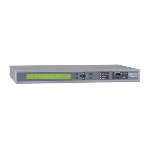
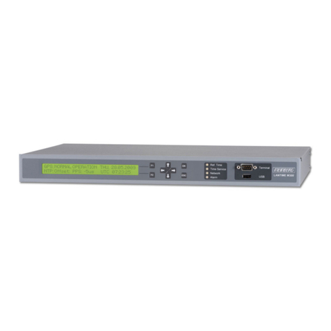
BRG Precision Products NTP100B User manual

1
BRG NTP100B Time Server
Stratum 1 GPS Synchronized Time Server
USER MANUAL
BRG Precision Products
600 N. River Street
Derby, Kansas 67037
http://www.brgproducts.com
7/30/2020

2
Table of Contents
1 Introduction ............................................................................................................................. 4
2 Installation ............................................................................................................................... 4
2.1 Location ............................................................................................................................... 4
2.2 Connections ......................................................................................................................... 5
2.2.1Antenna ............................................................................................................................. 5
2.2.2 Power ................................................................................................................................ 5
2.2.3 Network ............................................................................................................................. 5
2.2.4 Front Panel Display and Control ........................................................................................ 6
3 Configuration........................................................................................................................... 6
3.1 Web Page ............................................................................................................................ 6
3.2 Default IP address is 192.168.1.15 ...................................................................................... 6
3.2.1 Network Setup .................................................................................................................. 8
3.2.2 GPS Lock, Signal, and Current Time Information .............................................................. 9
3.2.3 Use DHCP ........................................................................................................................ 9
3.2.4 IPv4 Address ..................................................................................................................... 9
3.2.5 IPv6 Address ..................................................................................................................... 9
3.2.6 IPv6 Link Local .................................................................................................................. 9
3.2.7 IPv6 Temporary ................................................................................................................10
3.2.8 Mask HTTP access on Subnet .........................................................................................10
3.2.9 Mask NTP access on Subnet ...........................................................................................10
3.2.10 Netmask .........................................................................................................................10
3.2.11 Gateway .........................................................................................................................10
3.2.12 MAC ...............................................................................................................................10
3.2.13 Echo GPS Strings Checkbox ..........................................................................................10
3.2.14 Serial TTL Level Outputs Checkbox ...............................................................................11
3.2.15 Debug Output Checkbox ...............................................................................................11
3.2.16 Unit Name ......................................................................................................................11
3.2.17 Password .......................................................................................................................11
3.3 Display Configuration ..........................................................................................................11
4 Troubleshooting .....................................................................................................................14
4.1 GPS Lock ............................................................................................................................14
4.2 Finding the IP Address ........................................................................................................14
4.3 Resetting to Factory Defaults ..............................................................................................15
5 Specifications .........................................................................................................................15
5.1 Time Server Features and Specifications ............................................................................15
5.2 GPS Module Specifications .................................................................................................15
5.3 Antenna Specifications ........................................................................................................16
3
6 Warranty Agreement ..............................................................................................................17
7 Payments and Returns ...........................................................................................................20

4
1 Introduction
The BRG Network Time Server is a simple to use GPS based time server that will supply
accurate Stratum 1 time for all computers and time keeping devices on the network. The BRG
time server incorporates the proven TimeMachines NTP engine to provide accurate and reliable
time. By placing a time server on the local network, NTP time packets are provided, without
requiring systems to go to the Internet to obtain time synchronization. The system uses an active
GPS antenna to maintain the current time as broadcast by United States GPS satellites. With this
device installed on your local network, there is no longer the worry that if the Internet connection
goes down, time synchronization is lost across the network.
The rack mount device can be placed anywhere within the network layout. The built in high
sensitivity GPS receiver is able to lock on to multiple satellites, in some cases, from within many
buildings or from a window location. The dome outdoor antenna includes 25 feet of antenna
cable, plus another 100 foot extension cable for a total length of 125 feet. Additional cable may
be added as needed.
Setup and use of this time server is straightforward. Simply connect both the included power
supply and the GPS antenna to the base unit and then connect the base unit to the local network.
Go to a computer on the network and browse to the device at its default address to enter the
software setup within the control box. Set parameters to match your network and the system will
start to send out time packets to any device on the system that asks for an update from it.
Multiple servers may be setup to provide redundancy and more capacity.
When paired with our digital Power over Ethernet (PoE) clocks, synchronized time is assured no
matter the state of your network, or the state of the internet time server the clocks are pointed to.
Accuracy is also improved because the network delay of the internet is highly variable, while the
local LAN connection is likely sub-millisecond delay.
BRG NTP time servers are suited to any application where coordination of events at multiple
locations is required. Without coordinated network time, searching for problems across multiple
system logs becomes much more difficult. Education, industrial facilities, military installations,
public safety command rooms, government, broadcasting, and hospitals are all candidates
for synchronized time systems.
2 Installation
2.1 Location
To receive GPS signals, the Time Server's antenna must be located in a location where it can
“see” the sky. Both indoor and outdoor antennas are included. The GPS module itself is highly
sensitive and able to “see” the GPS satellite signals from within many structures. Multi-Story or
metal structures may block the GPS signals such that the antenna must be located elsewhere. In
these cases, the GPS antenna may be located in a window. The Time Server unit can be located
anywhere on the network. All that is required is power and a wired network connection. In the
worst case, an outdoor antenna may be required.

5
2.2 Connections
Time Server Rear View
2.2.1Antenna
The outdoor dome GPS antenna is connected through the SMA connector on the rear of the Time
Server. The outdoor antenna uses an SMA to BNC adapter to match the outdoor antenna cable.
The antenna includes 25’ cable with a BNC connector. If the antenna cable is extended, the
cable connections must be located indoors or otherwise protected from the elements. The BNC
connectors are not waterproof. The swivel mount allows the antenna to be mounted in a variety
of locations. For best reception, mount the antenna in a location that has a wide view of the sky.
2.2.2 Power
A UL Listed 5 volt DC power supply is supplied with the unit. Connect one end to a standard
United States 110-120 Volt outlet and the barrel connector to the rear of the Time Server. The
time server will begin trying to find the GPS satellites. On power-up, synchronization to the GPS
satellites will take several minutes. No battery backup of position is provided to allow for a
warm start so the Time Server is always starting from scratch in determining its location to
achieve GPS lock. The time server maintains time during power loss, but the LED display will
blank and the NTP time server engine is shut down.
2.2.3 Network
Connect the 10/100 RJ45 port on the back of the Time Server to a network connection. Verify
that the network settings are correct for your system. See the configuration section of this manual
for more information on doing this.

6
2.2.4 Front Panel Display and Control
The front panel of the Time Server includes an LED alphanumeric display and four control
buttons. When the time server is first powered on, hours, minutes and seconds will appear on the
display. A green “S” sync indicator will display when the time server is locked and sync’d to the
GPS time signal. If the GPS signal is lost, the “S” will turn off.
3 Configuration
3.1 Web Page
Default password is 'tmachine'
3.2 Default IP address is 192.168.1.15
All Time Server parameters are accessed on the configuration web page. The page can be
accessed by pointing any web browser at the IP address of the Time Server. The initial IP
address is 192.168.1.15 from the factory.

7
Illustration 1: Password Page
Default password is 'tmachine'

8
Illustration 2: Parameters Page
The time server must
3.2.1 Network Setup
By default the network parameters are setup to static address 192.168.1.15. The Time Server is
able to use DHCP, but the rest of the network will need to be able to automatically adjust to its
IP address should it change. This would involve setup with DHCP and DNS systems. Usually,

9
static setup is recommended. Addresses in the Network section must be entered in IPv4, dotted
quad, format.
All of these parameters require a restart for changes to take effect.
3.2.2 GPS Lock, Signal, and Current Time Information
At the top of the Time Server Configuration page is status information about the software
version in the Time Server and from the GPS module in the Time Server. The Firmware Version
is displayed and should be known before calling for support. The “GPS:” label will state whether
the GPS is locked to satellite signals or not. A “LOCKED” status in green letters is required for
operation. The “Signal Strength” line will give the signal strength of the top three satellites being
received. The possible range is from 0 to 99dB SNR. The time server will use as many satellites
as it can receive for the greatest possible accuracy. The current time is also displayed at the top
of the web page. The time zone is determined automatically from the browser settings. The time
is updated when the page is loaded (and GPS is locked) and thereafter is dependent on the
system clock of the web browser. Over time this value will drift based on the characteristics of
the HW clock in the browser hardware. Refreshing the page will update the time.
3.2.3 Use DHCP
Checking this option will tell the Time Server to ignore the other IP address settings and request
an IP address from the network's DHCP server at startup.
3.2.4 IPv4 Address
If the DHCP option is not being used, then the IP address of the unit set to by entering a standard
IPv4 dotted quad in this field. 192.168.1.15 or 10.10.0.96 are examples of acceptable formats for
this field.
3.2.5 IPv6 Address
This is the 128 bit IPv6 address of the device either statically entered of determined by DHCP.
The first 64 bits indicate the network address and the last 64 bits are user defined for their
network. Please note that a user should still setup the device as initially using IPv4. They can
then set an IPv6 address and/or view the IPv6 temporary. The web page can be accessed using an
IPv4 and/or IPv6. The time server will respond to Ping, Ping6, rdate and rdate -6.
3.2.6 IPv6 Link Local
This address is only valid for communications within the network segment (link) and is required
for stateless address auto-configuration. Neighbor Discovery Protocol is part of the IPv6 protocol
and uses stateless address auto-configuration. This address begins with prefix fe80::/64. The last

10
64-bits are based on the MAC address of the time server. This address is unique to each time
server and not modifiable.
3.2.7 IPv6 Temporary
This is a default address based on the network address and the MAC address. The time server
uses Neighbor Discovery Protocol to find the network address. The last 64-bits are based on the
time server’s MAC address. This address is unique to each time server and not modifiable. The
time server will default to this address to serve time if the IPv6 address has not been set,
otherwise the modifiable IPv6 address is used to serve time.
3.2.8 Mask HTTP access on Subnet
This checkbox will enable HTTP (web browser) access only on the time server’s configured
subnet. This has the effect that the time server will only respond to requests for the web page if
they come from the same subnet as the time server is configured on. This is a security feature to
limit the access to the configuration of the device only to the local subnet.
3.2.9 Mask NTP access on Subnet
This checkbox will enable NTP access only on the time server’s configured subnet. This allows
the time server to ignore requests for time from all devices that are not on the same subnet and
provides a measure of security and protection from denial of service attacks.
3.2.10 Netmask
The Netmask entry determines what addresses are on the local network and what addresses are
reached through the Gateway. Typical Netmasks are 255.255.0.0 or 255.255.255.0. Consult the
network administrator for more information on who this entry should be set.
3.2.11 Gateway
The Gateway IP address is used when a destination address is determined to not be on the local
network. Consult the network administrator for this setting.
3.2.12 MAC
This is an information only field and displays the MAC address of the Time Server.
3.2.13 Echo GPS Strings Checkbox

11
This box must be checked at all times.
Checking this option will tell the unit to copy all received data from the GPS
module's serial port to the serial port on the back of the Time Server. The copied
strings are the standard NMEA GPS data strings.
3.2.14 Serial TTL Level Outputs Checkbox
This box must be checked at all times.
Checking this option will enable the TTL level outputs of the serial port. These are found on Pins
7, 8, and 1. To receive the actual NMEA strings, the “Echo GPS Strings Checkbox” must be
checked. Pin 7 is the data from the GPS module, Pin 8 is data that will be sent to the GPS
module through the RS-232C port echo'd at TTL level. The data pins are duplicates of the RS-
232C data found on Pins 2 and 3, but are provided before conversion to RS-232C levels. Pin 1 is
the 1 PPS output. The 1 PPS output is a very narrow signal on the order of 1 uS in width, active
high.
3.2.15 Debug Output Checkbox
The debug output checkbox will tell the unit to output debug and operational information to the
serial port.
3.2.16 Unit Name
This can be any alpha numeric name up to 20 characters long.
3.2.17 Password
The password field displays the current password. To change it, enter a new password, push Save
and then Reboot for it to take effect. Time Server passwords are limited to12 characters.
The default password is “tmachine”
3.3 Display Configuration
The time server front panel buttons are used to control and configure only the display and not the
time server engine. Display configuration is accomplished by editing parameters using a simple
menu system. Only four buttons are used to navigate the menu. The Mode button enters the
Menu. The Up and Down buttons move up and down through the menu items, and are used to
change parameter values. The TC button is used to save any changes and exit the menu system.

12
Pressing the blue TC button will display the date (MMDDYY). Pressing TC again will display
the display firmware version number. Pressing TC again will return to the main time display.
The display will automatically return to the main time display after 10 seconds of no button
activity.
Menu Operation - Press the Mode button to access the menu system. Using the Up and Down
buttons, select the desired menu item. Press the Mode button again to display the parameter. For
menu items above 19, press Mode again to access the menu’s second level. When a one appears,
indicating the second level menu, press the Up or Down buttons to select the desired menu item,
then press Mode to display the parameter value. Press the Up or Down buttons to change the
parameter value. Once the parameter value is changed, press Mode to back out of the item and
move to another item, or press the TC button to save and exit the menu system. Pressing the TC
button at any time will save your changes and exit the menu system.
Pressing the Mode button while a parameter value is displayed will back up one level. Press Up
or Down to move to the next mode item. Pressing the Down button until mode 0 is reached will
exit the menu system. Pressing the TC button also exits the menu system. The menu will
timeout and return to normal operation after 60 seconds in inactivity.
A special operation menu is available for restoration and diagnostic purposes. Pressing and
holding the mode button will cause either four one’s or four two’ to be displayed. Four one’s
means no configuration has been stored in secondary memory. Four two’s means a previous
configuration has been stored in secondary memory.
Continuing to hold down the mode button allows shortcut menu operations. The one’s or two
will disappear and the display will begin counting up from 0. Special commands will execute if
you release the mode button while one of the numbers are displayed. The special commands
are:
1=Software reset
2=Restore factory defaults, once the 2 appears, release the mode button and momentarily press the TC
button
3=Restore customer defaults from secondary memory (if previously stored) , once the 3 appears, release
the mode button and momentarily press the TC button
4=Store customer defaults in secondary memory, once the 4 appears, release the mode button and
momentarily press the TC button
First
Menu
Level
Mode
Number
Second
Menu
Level
Value
Range
Mode Description and Instructions
0 N/A 00:00
to
23:59
Exit Menu System
Simply press the Up button to advance the time, or the Down button to decrement the
time. The longer the buttons are held down, the faster the time will change. Pressing

13
First
Menu
Level
Mode
Number
Second
Menu
Level
Value
Range
Mode Description and Instructions
the TC button will also exit the menu system.
21 1 -12 to 12
hours
from UTC
Time Zo
ne Offset
This value determines the number of hours to add or subtract from Universal
Coordinated Time. The clock’s internal time base is Universal Coordinated Time
(UTC, GMT or ZULU). A time zone offset may be applied to each time source. See
also Mode 33 for forced half hour and one hour offsets. For accurate time zone
information, see http://www.timeanddate.com
23 1 12, 24
12
or 24 hour display format
This mode selects either 12 or 24 hour display format for each four digit display when
displaying real time.
(default=12)
24 1 0,10
Daylight /
Standard Time
This mode selects the rules to use when automatically switching between Daylight
and Standard time. The rules for various locations are:
0=disable daylight time (default)
10=user defined rule – see also Mode 52 and Mode 45-20, Mode 45-21
33 1 0-5
code
Force Time Advance
This mode optionally forces a 30 to 60 minute time advance.
0= no advance (default),
1=30 minute advance,
2=60 minute advance,
3=30 minute advance during daylight savings time only,
4=60 minute advance during daylight savings time only,
5=45 minute advance.
This is used in areas that have a 30 to 60 minute advance over the area time
zone. For example, Mumbai, India’s time zone offset is +5:30. To configure
the time zone, first set the respective zone to +5 hours using Mode 21. Then
set the same respective zone in Mode 33 to 1.
45 20 111 –
3231
Custom
Daylight Saving Rule
–
Starting Value for Mode 24
-
n=10
Default=327 – (Second Sunday in March)
Values for rule driven custom daylight saving time for Mode 24-n=10. The
format is MMRD, where MM = month (1-12), R = instance of the select day of
the week (1-5 5=last instance), D = day of the week (1-7), where 1=Monday
and 7=Sunday. For example, the number 357 represents the last Sunday in
March, or 1117 represents the First Sunday in November. If the value >2000
then the right two digits represent the day of the month. The left two digits,
minus 20, equal the month. For example, March 15th = 2315, April 1st =
2401. The day of the year derived from this rule is stored in Mode 52-1. If
the DST date is a fixed day (i.e. 15th of the month), then set this mode to
0 and enter the Julian day into Mode 52-1 instead.
See also Mode 24-n=10 and Mode 45-21
45 21 111 –
Custom Daylight Saving Rule
–
Ending Value for Mode 24
-
n=10

14
First
Menu
Level
Mode
Number
Second
Menu
Level
Value
Range
Mode Description and Instructions
3231
Default=1117 – (First Sunday in November)
Values for rule driven custom daylight saving time for Mode 24-n=10. The
format is MMRD, where MM = month (1-12), R = instance of the select day of
the week (1-5 5=last instance), D = day of the week (1-7), where 1=Monday
and 7=Sunday. For example, the number 357 represents the last Sunday in
March, or 1117 represents the First Sunday in November. If the value >2000
then the right two digits represent the day of the month. The left two digits,
minus 20, equal the month. For example, March 15th = 2315, April 1st =
2401. The day of the year derived from this rule is stored in Mode 52-2. If
the DST date is a fixed day (i.e. 15th of the month), then set this mode to
0 and enter the Julian day into Mode 52-2 instead.
See Mode 24-n=10 and Mode 45-20.
4 Troubleshooting
4.1 GPS Lock
Getting GPS lock on the Time Server is required for it to function. Most GPS lock issues come
down to issues with Antenna location, or cabling. If there are problems getting GPS lock (sync
indicator “S” does not appear on the display), try moving the antenna outside. If it does, try a
window and see if lock is maintained. If that works, move the antenna back to its original
location and see if lock is lost. This will help determine where lock can be received and where it
cannot. If no lock is achieved outdoors, then something is either wrong with the cabling or the
Time Server itself. Contact support.
4.2 Finding the IP Address
If the IP address of the Time Server is forgotten, there are a few ways to go about finding its IP
address. The first is to use a serial terminal program such as Hyper-Terminal or something
similar. Set the communications parameters of the terminal program to 115200,N81. Connect a
straight through cable between the computer and the Time Server and cycle power on the Time
Server. The IP address is printed during startup. If the Time Server is using DHCP, then it is
possible to look up the units IP address on the DHCP server by looking at the list of leases. Look
for a MAC address in the lease list that starts with 00:50:C2. This will likely be unique in the
DHCP lease list. The IP address associated with this MAC address should be tried. The third
possible way to determine the IP address is to simply check several of the devices using the Time
Server on the network to see how they are programmed. If they have a specific IP address
programmed into them for time keeping, then that may be the Time Server's base IP address. If a
domain name has been assigned to the Time Server, doing a command like “ping
timeserver.your-company.com” might show the time servers address as well.

15
4.3 Resetting to Factory Defaults
Jumper J8
A: Reset to Factory B: Normal Operation
Jumper J8 on the inside of the time server is used to reset the units software settings to factory
original. This is useful when a password is forgotten or the IP address cannot be determined. To
do this, remove the 4 screws from the bottom of the unit. Move J8 to the “A” position and apply
power. After a few seconds, remove the power connection, replace J8 to the “B” position and
reassemble the unit. It should now have the factory default password and IP address information.
5 Specifications
5.1 Time Server Features and Specifications
• Receive time information from GPS satellites anywhere on the surface of the earth
• RFC1119/1305 NTP Protocol to serve time (Network Time Protocol)
• RFC1769/2030/4330 SNTP Protocol (Simple Network Time Protocol)
• Server Time Level: Stratum 1
• Server Time Precision: better than 5mS + network jitter.
• 10M/100M adaptive network interface
• Unit is capable of serving 350+ synchronizations per second. That provides support for over
300,000 devices updating every 15 minutes on the network.
• Active GPS outdoor antenna and 125’ of antenna cable included.
• Compliant with FCC Part 15, class B for radiated emissions and is a lead free product.
• Power Requirements: less than 4 Watts continuous at 5 volts DC.
• Environmental Requirements: Commercial temperature range, 0-70C, 95% humidity non-
condensing. Altitude -304m to 18,000m.
• Networking: Static or DHCP IPv4 addressing. Standard browser interface for setup.
• Serial port supports both RS-232C levels and TTL (+3.3V) outputting standard NMEA
information strings, as well as the 1PPS signal at TTL levels.
• LED alphanumeric front panel display with display configuration buttons
• Rear Connections: Power, Cat5 Ethernet, Serial, and GPS antenna via SMA connection.
• Dimensions: 19” (482 mm) W x 1 ¾” (44 mm) H x 8” (203 mm) D
5.2 GPS Module Specifications
• Based on SiRF GSC3e Lpx chipset.
• 20 channel low power receiver module
• Sensitivity: -144dBm, C/N0=26dBHz
• GPS Time Precision: <1us, typical +/- 300ns ref UTC.
• Antenna Connection: 1575.42MHz (L1 Band) at a level between -135dBm and -159dBm into
50 Ohm impedance. Maximum input return loss is -9dB.
• TTFF (Time To First Fix):Cold start @-125dBm typically 33 seconds, Re-acquisition (<10s
obstruction) typically 1 second

16
5.3 Antenna Specifications
• Active dome antenna with swivel mount.
• Size: 3.5” (89 mm) diameter x 8” (203 mm) high
• Amplifier: LNA +20dB Noise: 1.5dB VSWR: 2.0 Voltage: 2.7-6.0V.
• Cable: RG58, BNC male.
• Environmental: -40 to +85C
• Waterproof to IPx6
(Specifications are subject to change without notice)

17
6 Warranty Agreement
Warranty Agreement
BRG Precision Products One Year Warranty
1. Term of Coverage
Coverage will be for 1 year. Claims must be made during the Warranty Period. This Agreement is not
renewable. The warranty becomes null and void if complete payment is not made within the terms
specified under Terms of Payment.
2. Warranty
BRG Precision Products, Inc. warrants the Product against defects in workmanship and materials during
the Coverage Period.
3. Coverage
BRG Precision Products, Inc. will, at its option, repair or replace the defective Product free of charge,
provided that you notify BRG Precision Products, Inc. of the Product defect within the Coverage Period,
and provided that BRG Precision Products, Inc. through inspection establishes the existence of such a
defect and that it is covered by this Agreement. BRG Precision Products, Inc. will, at its option, use new
and/or reconditioned parts in performing warranty repair and building replacement products. BRG
Precision Products, Inc. reserves the right to use parts or products of original or improved design in the
repair or replacement. If BRG Precision Products, Inc. repairs or replaces a Product, the warranty
continues for the remaining portion of the Coverage Period without extension. All replaced Products and
all parts removed from repaired Products become the property of BRG Precision Products, Inc. BRG
Precision Products, Inc. covers both parts and labor necessary to repair the Product, and return shipment
to the Customer via a BRG Precision Products, Inc.-selected non-expedited surface freight within the
contiguous United States and Canada. Alaska and Hawaii return shipments to the Customer are via non-
expedited air freight.
4. What Is Not Covered
This Agreement does not cover costs related to the removal, installation, or field troubleshooting of the
Product under the terms of the Agreement if, and not limited to:
a) the Product has been misused, neglected, improperly installed, physically damaged or altered, either
internally or externally, or damaged from improper use or use in an unsuitable environment;
b) the Product has been subjected to fire, splashed water (unless specifically ordered to be water
resistant), submersion into any liquid, generalized corrosion, biological infestations, or high input voltage
including lighting strikes and generators operating outside the limits of their Product specifications;
c) repairs have been done to it other than by BRG Precision Products, Inc. or its authorized service
centers, or as assigned by BRG Precision Products;
d) the Product is used as a component part of a Product expressly warranted by another manufacturer;
e) the Product's original identification (trade-mark, serial number) markings have been defaced, altered,
or removed;
f) the Product is located outside of the United States and Canada;
g) the customer has misrepresented the Product information provided to BRG Precision Products, Inc. in
order to receive coverage under the terms of this Agreement. This Agreement does not warrant
uninterrupted or error-free operation of the Product;
h) Product malfunction or damage resulting from electromagnetic or solar radiation;
i) Shipping charges to the factory more than 30 days after first receiving the product;
j) Undesirable operation resulting from changes to public law after the product was purchased, such as
changing the dates for daylight saving time.

18
k) Normal wear and tear relating to the non-operating functions of the equipment such as discoloration
from direct sunlight, heat, etc.
5. Disclaimer and Limitation of Liability
TO THE EXTENT PERMITTED BY APPLICABLE LAW, OTHER THAN THE EXPRESS
WARRANTY SET FORTH IN THIS AGREEMENT, BRG PRECISION PRODUCTS, INC. MAKES
NO ADDITIONAL WARRANTIES, EXPRESS OR IMPLIED, AND DISCLAIMS ALL IMPLIED
WARRANTIES, WHETHER IN FACT OR BY OPERATION OF LAW, STATUTORY OR
OTHERWISE, INCLUDING WARRANTIES OR CONDITIONS OF MERCHANTABILITY AND
FITNESS FOR A PARTICULAR PURPOSE. ANY WARRANTIES THAT MAY NOT BE
DISCLAIMED UNDER APPLICABLE LAW ARE LIMITED IN DURATION TO THE WARRANTY
PERIOD. NO WARRANTIES, EXPRESS OR IMPLIED, WILL APPLY AFTER THIS PERIOD. IN NO
EVENT WILL BRG PRECISION PRODUCTS, INC. BE LIABLE FOR ANY SPECIAL, INDIRECT,
INCIDENTAL OR CONSEQUENTIAL DAMAGES, LOSSES, COSTS OR EXPENSES HOWEVER
ARISING WHETHER IN CONTRACT OR TORT INCLUDING WITHOUT RESTRICTION ANY
ECONOMIC LOSSES OF ANY KIND, ANY LOSS OR DAMAGE TO PROPERTY, ANY
PERSONAL INJURY, ANY DAMAGE OR INJURY ARISING FROM OR AS A RESULT OF
MISUSE OR ABUSE, OR THE INCORRECT INSTALLATION, INTEGRATION OR OPERATION
OF THE PRODUCT. SOME STATES DO NOT ALLOW THE EXCLUSION OR LIMITATION OF
INCIDENTAL OR CONSEQUENTIAL DAMAGES SO THE ABOVE LIMITATION MAY NOT
APPLY TO YOU. BRG Precision Products, Inc. neither assumes nor authorizes any other person to
assume for it any other liability in connection with the repair or replacement of the Product.
6. Claim Limits
Claims are limited to repair or replacement, or if in BRG Precision Products, Inc.'s discretion that is not
possible to reimbursement up to the purchase price paid for the Product. In no event will BRG Precision
Products, Inc.'s liability under this Agreement exceed the purchase price paid for the Product.
7. Cancellation
You may cancel this Agreement by providing to BRG Precision Products, Inc. written notice of your wish
to cancel.
8. Insurance
This Agreement is not a contract of insurance.
9. Amendment and Waiver
No amendment, supplement, consent or waiver, express or implied, to or of any provision of this
Agreement will be effective unless in writing signed by the parties hereto and then only in the specific
instance and for the specific purpose given.
10. Assignment
The Customer may assign or transfer this Agreement provided BRG Precision Products, Inc. is advised by
the Customer in writing of such assignment and the new system owner's information.
11. Governing Law
This Agreement will be governed by and interpreted exclusively in accordance with the laws of the State
of Kansas, without reference to provisions concerning conflicts of laws. The provisions of the United
Nations Convention on Contracts for the Sale of Goods are hereby excluded.
12. Arbitration
Any controversy or claim arising out of or relating to this Agreement, or the breach of it, shall be settled
by arbitration in accordance with the relevant rules of the American Arbitration Association, and
judgment on the award rendered by the arbitrator may be entered in any court having jurisdiction thereof.
The place of arbitration shall be Wichita, Kansas, United States of America. There shall be one arbitrator.

19
13. Severability
If any provision of this Agreement is found by any court or arbitrator to be invalid, illegal or
unenforceable, the validity, legality and enforceability of the remaining provisions will not be affected
thereby.
14. Entire Agreement
This Agreement constitutes the entire contract between the parties concerning the subject matter of this
Agreement and supersedes all marketing brochures and other expectations, understandings,
communications, representations and agreements, whether verbal or written, between the parties. THIS
AGREEMENT GIVES YOU SPECIFIC LEGAL RIGHTS AND YOU MAY ALSO HAVE OTHER
RIGHTS WHICH VARY FROM STATE TO STATE.

20
7 Payments and Returns
Once a return authorization number is obtained, ship the products to:
BRG Precision Products
Attn: RA# xxxxxxx (where xxxxxxx is the authorization number provided)
600 N. River Street
Derby, KS 67037
Optional Extended Warranty:
A two-year extended warranty is available. The extended warranty must me purchased before the end of
the standard warranty. The two-year extended warranty costs 20% of the product purchase price.
Optional Advanced Replacement Service (“Hot Swap”):
For critical applications, BRG Precision Products recommends purchasing a complete backup product. If
a backup product is too expensive or the application is only semi-critical, BRG Precision Products
recommends the optional
Replacement Service ("Hot Swap")
This service allows the customer to receive a replacement product right away to replace a defective
product that is covered under warranty. BRG Precision Products will pay for ground shipping to send the
replacement product. The customer is responsible for expedited shipping charges over the cost of ground
shipping. The customer is responsible for shipping charges to return the defective product. The
Replacement Service is only available for shipments to the U.S. and Canada.
When the customer receives the replacement product, the defective product must be returned to the
factory within 30 days. The invoice for the replacement product will then be voided; otherwise, the full
invoice amount for the replacement product is due. This service is only available in conjunction with
warranty repairs.
This replacement service may be purchased for 10% of the products purchase price at the time of the
initial purchase. The replacement service may also be purchased after the initial product purchase and
before the standard warranty expires for 15% of the product purchase price. The term of this service ends
when the warranty expires. This service may be repurchased for 10% of the product purchase price when
a two-year extended warranty is purchased. The product replacement service is only available on
selected models.
30 Day Return Policy:
No returns will be accepted without prior written authorization of BRG. Incorrect merchandise received
will receive prompt re-shipment of correct items. Incorrect merchandise, other than custom items, may be
returned, shipped prepaid, and will be exchanged on an equivalent basis.
Merchandise, other than custom items, that cannot be used may be returned at a 25% restocking charge if
items are shipped prepaid in the original boxes. Carrier is responsible for parts damaged in shipment. The
customer should have driver sign for damaged carton on delivery receipt and make a claim with the
freight company. Please insist that the carrier's representative conduct an inspection, and retain all
packing materials for the inspector. Please report promptly for immediate follow-up on short shipments.
No action arising from any sale by BRG may be brought by a customer more than one year after the date
of shipment.
Table of contents