BriarTek Orca DF-101 User manual
DF-101 User Manual
and Installation Guide
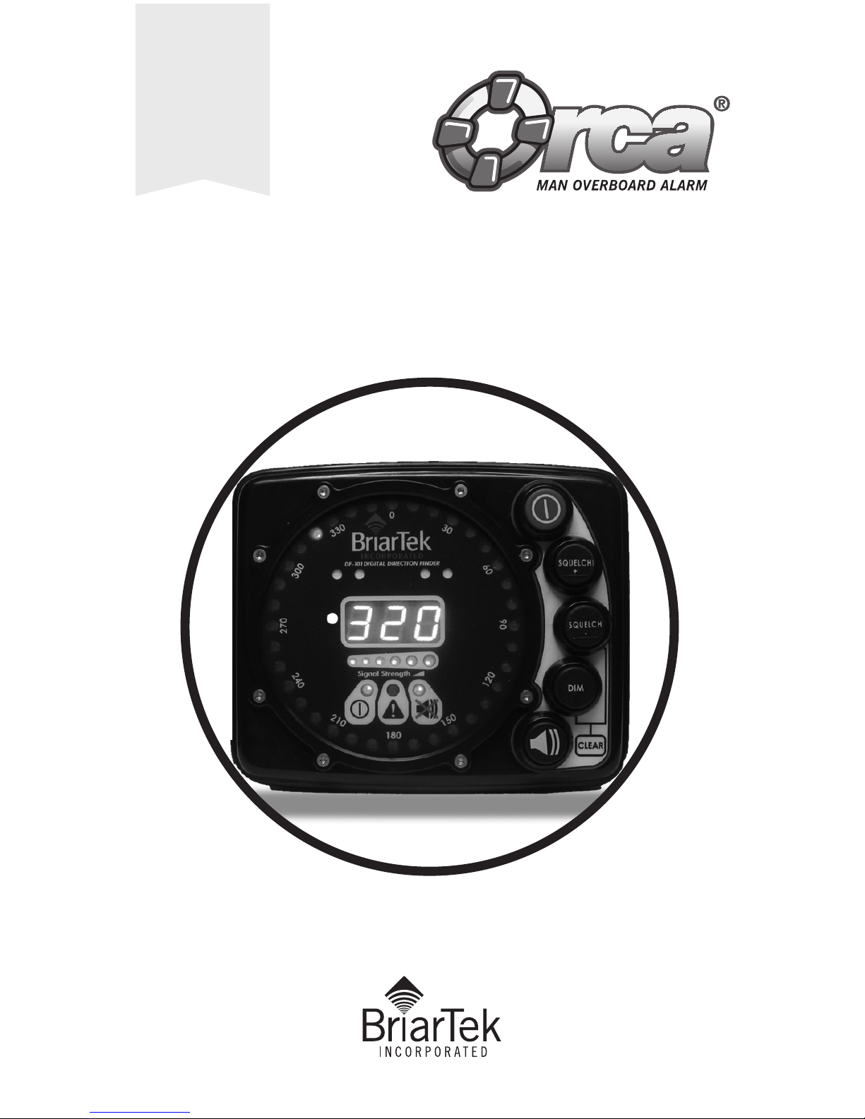
ORCA DF-101
IS AN
IDENTIFICATION
AND RECOVERY
SYSTEM FOR
NAVY FLEETS

2
BriarTek, Inc. Technical Support:
(703) 548-7892
Email: support@briartek.com
Web: www.briartek.com

3
Table of Contents
1.0 DF-101 Introduction ........................................................................ 5
2.0 DF-101 Parts Overview .................................................................... 5
3.0 DF-101 Functions............................................................................ 6
3.1 Power On/Off................................................................................... 6
3.2 Speaker .......................................................................................... 6
3.3 Clear .............................................................................................. 6
3.4 Squelch .......................................................................................... 6
3.5 Dim ............................................................................................... 7
3.6 Signal Strength................................................................................ 7
3.7 Warning.......................................................................................... 7
3.8 Default Settings ............................................................................... 7
4.0 Installation Notes............................................................................. 7
4.1 Display........................................................................................... 8
4.2 Antenna Array ............................................................................... 10
5.0 Small Boat Procedures ................................................................... 13
5.1 Set Up.......................................................................................... 13
5.2 Operation...................................................................................... 13
6.0 General Guidance for Bridge Watchstanders
and Small Boat Personnel ............................................................... 14
7.0 Direction Finder Maintenance.......................................................... 14
7.1 Inspection..................................................................................... 14
7.2 Testing ......................................................................................... 14
7.3 Antenna Element Replacement........................................................ 15
7.4 In-line Fuse Replacement................................................................ 15
7.5 Troubleshooting ............................................................................. 16
8.0 Parts List ...................................................................................... 18
9.0 DF-101 Specifications.................................................................... 20
10.0 Warranty....................................................................................... 22
4
1.0 DF-101 Introduction
The DF-101 direction finder is an interferometer signal processor and provides the
relative bearing to a 121.5 MHz transmission. Each DF-101 consists of a display
unit and an antenna array. This system is mounted on the navigation bridge and
small boat to assist in the location and recovery of an MOB.
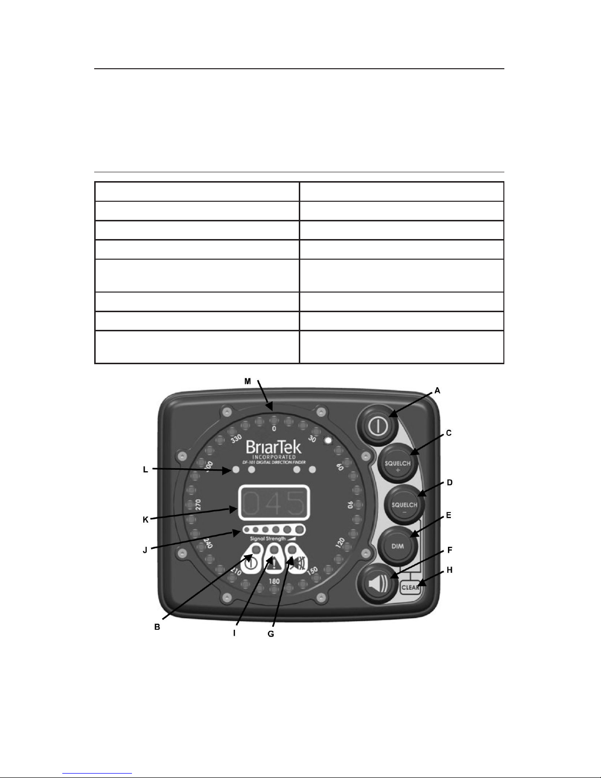
2.0 DF-101 Parts Overview
A– Power On/Off (Red) Button I– Warning LED
B– Power On/Off LED J– Signal Strength Indicator
C– Squelch Increase Button K– Numeric Bearing Indicator
D– Squelch Decrease Button L– Speaker (4 Ports)
E– Display Dimmer Button M– Circular Display Bearing Indicator
(36 LEDs)
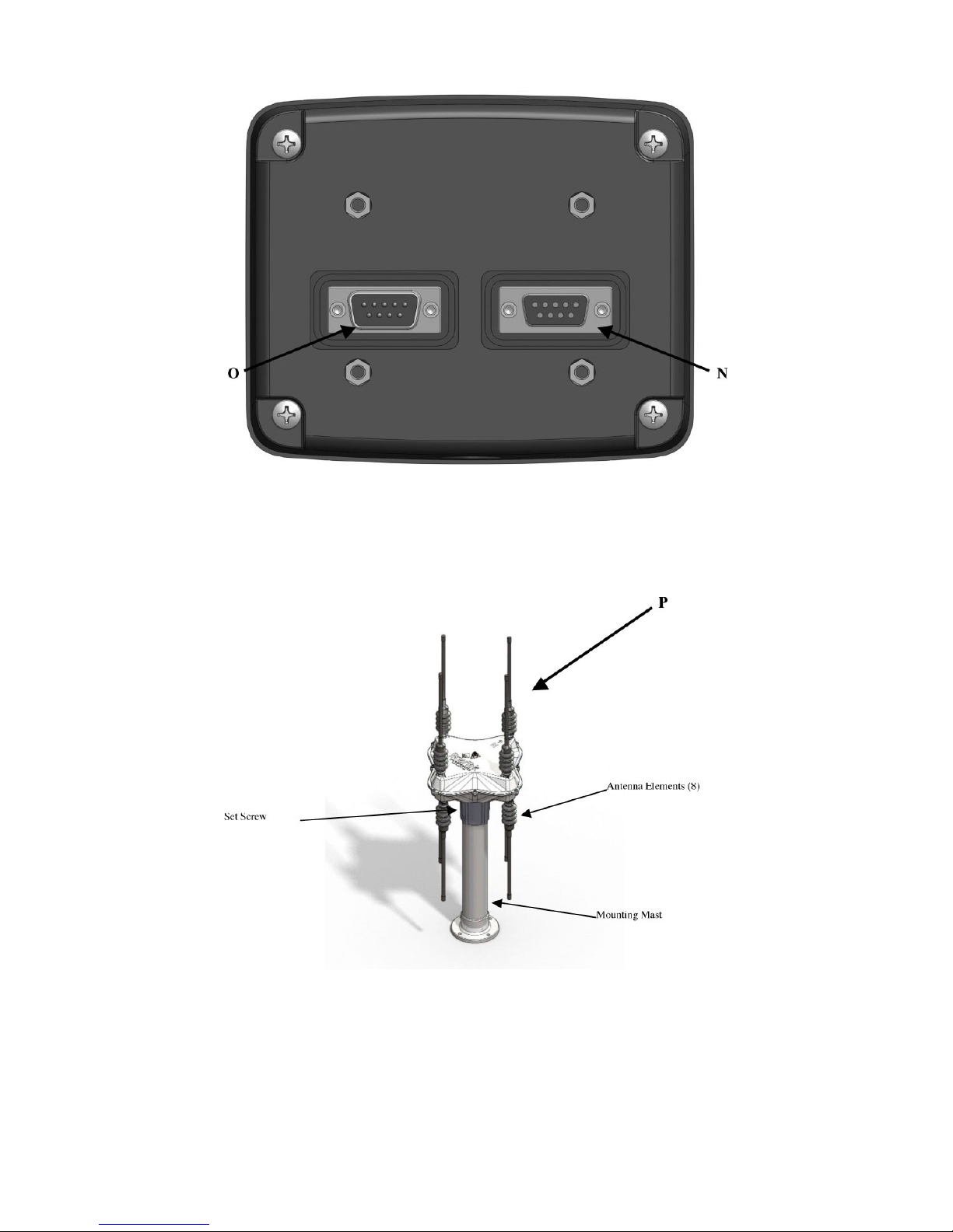
F– Speaker On/Off Button N– Data Connector
G– Speaker On/Off LED O– Power Connector
H– Clear (Depress Squelch Decrease
[D] & Dim [E] Simultaneously)
P– DF101 Antenna Array
Figure 1. DF-101 Display (Front View)
5
Figure 2. DF-101 Display (Back View)
Figure 2. DF-101 Display (Back View)

6
3.0 DF-101 Functions
3.1 Power On/Off
The Power On/Off button (A) provides power to the system and restores default
settings. When button is held down for at least one second, the display will perform
a system check to determine that the DF-101 is functioning properly. While it is
performing this check, all LEDs will illuminate. After the system check is complete,
the only remaining illuminated LEDs will be the Power On LED (B), the Speaker
On/Off LED and the Numeric Bearing Indicator (K) will display “---“. Note: the
illuminated Speaker On/Off LED indicates the speaker is off. Press the Speaker
On/Off button to turn on the speaker. Check to ensure the Warning LED (I) is not
illuminated; if the Warning LED is illuminated, service is required. To turn the
direction finder off, hold down Power button (A) for at least one second; all LEDs will
extinguish.
3.2 Speaker
The speaker (L) provides the audible indication of the received distress signal. The
Speaker On/Off button (F) toggles the speaker on and off. When the Speaker On/Off
LED (G) is illuminated, the speaker is off.
3.3 Clear
Clear (H) is used to clear the DF-101 internal data used to calculate bearing; it
resets to an un-averaged bearing value. Clear the display by depressing the Squelch
decrease button (D) and Dim button (E) simultaneously. When the data is cleared,
the bearing LEDs will illuminate in the same pattern as when the unit is first
powered on.
3.4 Squelch
Squelch is used to filter undesired signals that may be present at or near 121.5 MHz.
These signals are typically found in high traffic areas such as shipping channels, airport
flight paths, and populated areas. It is also used to reduce interference noise from
own ship RF emissions. Increasing squelch will cause a decrease in range of the DF.
Therefore it is recommended that the squelch be decreased when operating away from
high traffic areas in order to maximize system range.
Changing the squelch level: Press and hold the “Squelch +” button (C) or the
“Squelch –“ button (D) to enter squelch mode and increase/decrease the squelch
level. While in squelch mode, a squelch value will be displayed on the numeric
bearing indicator (K) as well as on the LED bearing indicators (M). Values for
squelch are 0-360. Release squelch increase/decrease button when desired squelch
level is achieved. The DF will return to bearing display mode five seconds after
release of button.

7
3.5 Dim
The display dimmer button (E) enables the user to dim the display LEDs. The
display has 3 levels of illumination. Push the button to decrease the illumination.
3.6 Signal Strength
The signal strength indicator LEDs (J) indicate the received signal strength on a
graduated scale from 0 to 6 (0 indicating weak/no signal and 6 indicating strong signal).
3.7 Warning
The warning LED (I) alerts the user to a failure in the system. If this LED is
illuminated, first turn off power (A) and check to ensure DB-9 data and power cable
connections (N & O) are fully secured. Turn on power (A). If warning LED is still
illuminated, see section 4.0, Maintenance and Troubleshooting procedures.
3.8 Default Settings
Default settings for the DF-101 are:
• Dim – High (brightest) value
• Squelch – Last saved value
• Speaker – OFF
NOTE: The system returns to the default settings when the DF-101 is turned on.
4.0 Installation and Repair Notes
The installation notes provided herein are intended to serve as a guide only. They do
not serve as material required for the certification of technicians for the installation,
repair or alteration of the ORCA® MOBI system.
NOTE: When replacing a DF-100 (see figure 4) with a DF-101, ensure that the
display and antenna are replaced. The DF-101 display does not function with the
DF-100 antenna; the DF-101 antenna does not function with the DF-100 display.
Figure 4. DF-101 display and antenna
8
4.1 Display
a. General. Display should be mounted in accordance with platform-specific ship
installation drawings (SIDs) for shipboard installation or BOATALT GEN47B
drawings for RHIB/LCPL installation. For ship installations, the display is typically
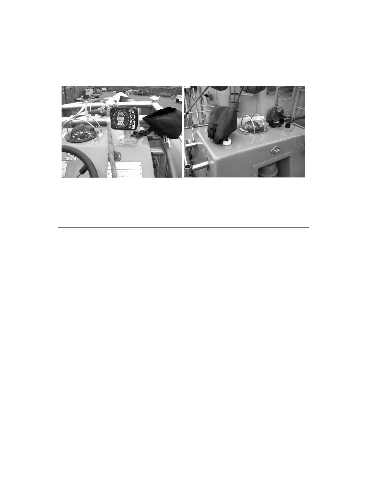
mounted near the conning officer’s station. On a ship’s small boat, the display is
mounted on the console.
b. Mounting the DF Display. Display bracket should be installed IAW SIDs or
BOATALT drawings. If installing on a RHIB or LCPL, see section 4.1.c. for
attaching the DF display hood.
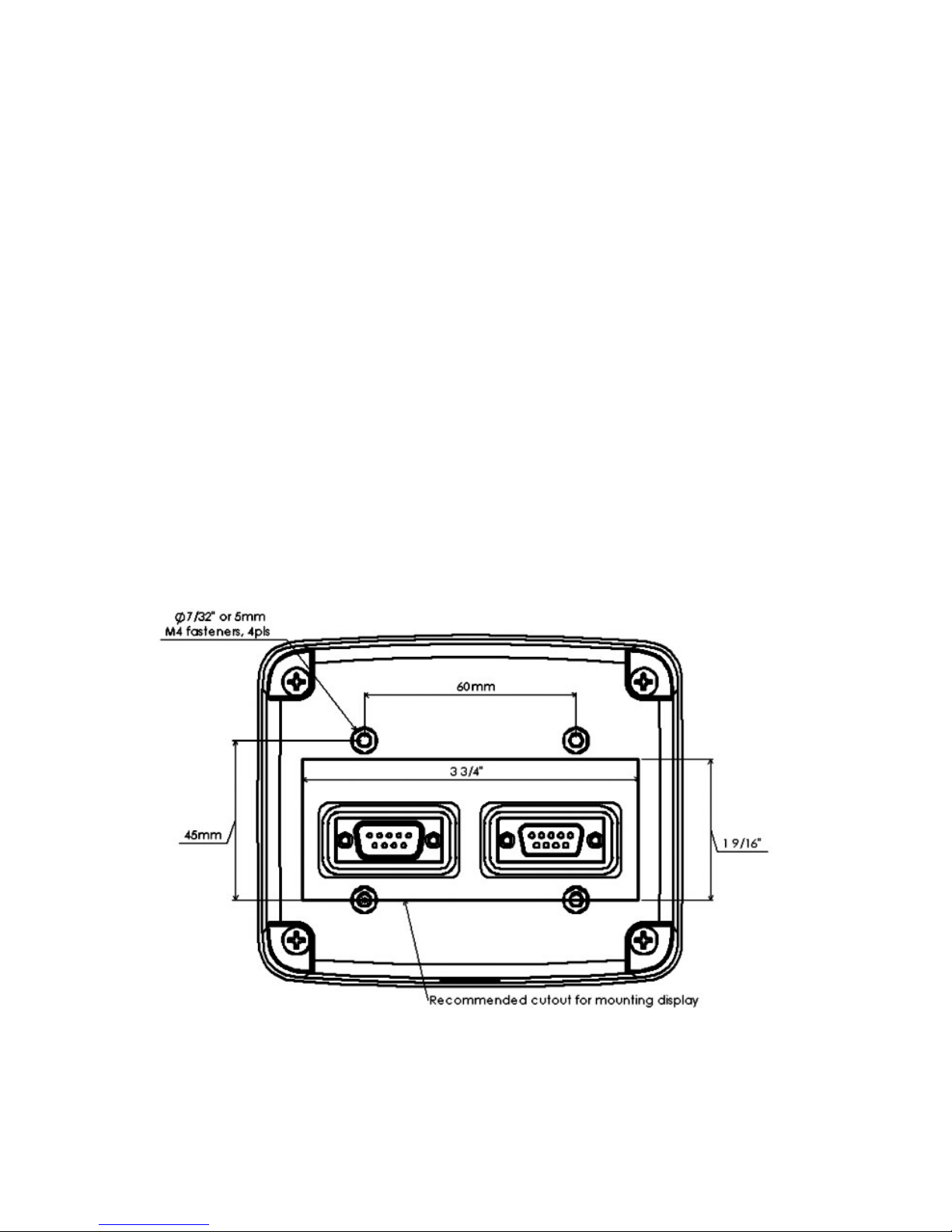
(1) Mate display to display bracket and attach using M4 fasteners, lock washers
and threadlock provided with the display.
(2) Attach power and data cables to the display. If the display will be installed
on a RHIB or LCPL, waterproof DB9 connectors with extended length gaskets
must be installed on the data and power cables. If replacing a DF-100 with a
DF-101 direction finder, replace the standard length gasket with the extended
length gasket provided. See figure 6. Please refer to electrical specifications in
Section 9.0, DF-101 Specifications, for connector requirements, cable pin-out
information and power & grounding requirements.
WARNING: Ensure power cable leads are connected correctly. Failure to do so
could result in DF display failure and will void warranty
Figure 5. DF-101 Display Mounting Hole Dimensions

9
c. Install DF Display Hood. If installing on a RHIB or LCPL, secure rubberized DF
display hood to the display bracket. You will need access to the inside of the
console to perform this.
(1) Remove forward-most bracket securing screw, washers (2) and locknut. See
figure 7. Set aside screw, washers and locknut in a safe location.
(2) Align the hood securing strap grommet with the hole in the display bracket.
Figure 6. DB9 Gaskets
Figure 7. DF Display Bracket
10
(3) From the exterior of the console, insert screw with washers (one outside and
one inside console). Secure with locknut on the interior of the console.
(4) Cover DF display with hood. See figure 9. While the DF display is not in use,
display should remain covered.
Figure 8. DF Display Hood – Figure 9. DF Display Hood –
display uncovered display covered
4.2 Antenna Array
a. General. The antenna array should be mounted IAW platform specific SIDs or
BOALTALT drawings. In general, the antenna array should be installed at the
highest point possible such as the ship’s mast and away from any obstructions
that would interfere with the DF’s line of sight to the MOB transmitter. In practical
application it is recommended that the antenna array is mounted a minimum of
3’ away from any adjacent objects (i.e., GPS antenna, VHF marine radio antenna,
stanchion, etc…) and located such that adjacent objects are non-planar.
b. Mounting the antenna array.
(1) Place antenna array onto antenna mast. Dimensional requirements for mast
fabrication are located in Section 9.0, DF-101 Specifications.
(2) Orient antenna array. Position the antenna such that the two opposing
antenna elements facing relative north point parallel to the bow of the vessel
(see figure 10). Relative north of the antenna array can be indentified by
locating the raised “N” text on top of the antenna housing and adjacent to the
top, forward looking antenna element. Additionally, there is a small pressure
relief valve on the bottom side of the antenna housing adjacent to the bottom,
forward looking antenna element.

11
Figure 10. DF-101 Antenna Orientation
(4) If array base and mast set holes are aligned at locations indicated in figure
11, continue to step (6).
Figure 11: Array Base Set Holes
(5) If array base and mast set holes are not-aligned, drill and tap mast to align
with new array base as follows:
i. Orient DF North Arrow to bow of vessel and use punch to mark new hole
location(s) on antenna mast (2 set holes on flat sides of square mast; 1 set
hole on round mast).
12
ii. Remove antenna array and cable if possible. On some masts, the cable will
not pass back through the mast. In this case, place a metal plate in front of
cable to prevent cable from being damaged when drilling.
iii. Using No. 7 (.201) drill bit, drill pilot holes (to be used for ¼ x 20 tap)
iv. Tap each pilot hole with ¼ x 20 tap using hand tap wrench. It is
recommended to back off two turns for every turn forward until the hole is
tapped through.
(6) Connect data cable. A waterproof DB9 connector with extended-length gasket
(see figure 6) must be used to maintain the water tight integrity of the antenna
array.
(7) Secure antenna array. Install a lock washer and flat washer onto a ¼-20 x
¾” fastener. All material should be 316 CRES. Apply anti-seize to threads
of ¼-20 fastener. Install fastener through the ¼” hole at the antenna array
mounting base and into the tapped mast. Do not over-torque or threads will
strip.
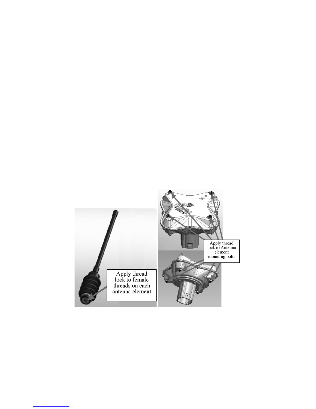
(8) Fasten antenna elements (qty 8). Apply threadlock to the threads of the
antenna elements and mounting bolts (see figures 12 & 13). Screw (hand-
tighten) each element on mounting bolts. Do not over-torque the antenna
elements. Wipe any excess threadlock from surrounding area.
Figure 12: Thread lock Figure 13: Mounting bolts
on antenna element

13
5.0 Small Boat Procedures
5.1 Set Up
a. Upon manning the small boat, ensure the boat’s power panel main breaker and
MOBI breaker are turned on.
b. Locate the DF Display. The display is mounted on the small boat (LCPL and
RHIB) console in front of the coxswain.
(1) Remove tethered display cover.
(2) Turn on power at the display. The display conducts a self-diagnosis for
approximately 3-4 seconds. The system is ready when the “Power On” LED is
illuminated.
c. Locate DF-101 antenna array. Antenna locations are as follows:
(1) 7/11 Meter RHIB – Mounted on transom or arch
(2) LCPL – mounted on cabin top, starboard side or cockpit bridge wing,
starboard side.
RHIB configuration – If the antenna and mast are in the horizontal position, raise
the antenna and mast to the vertical position and lock in place with the locking
pin. The MOBI DF antenna array may be stowed in the horizontal position when
the DF is not in use.
LCPL – If the antenna and mast are in the retracted position, extend upward and
secure with locking pin.
5.2 Operation
a. After the DF is ready to receive signal, and the boat is underway and making way,
establish the general direction to the MOB by communicating with the bridge.
NOTE: Do not immediately rely on the accuracy of the DF, as the signal coming
from the MOBI transmitter may reflect off the ship. This can produce a false
bearing on the small boat DF display.
b. Once there is some distance between the boat and the ship (50-100 yards,
depending on the position of the MOB relative to the ship), the DF display
bearings will become more accurate and should be used to determine the bearing
to the MOB.

14
6.0 General Guidance for Bridge Watchstanders
and Small Boat Personnel
a. When the DF receives the MOB signal, the bearing indicator LED on the display
will illuminate, indicating the relative bearing to the MOB. Circular display bearing
accuracy is ±5 degrees.
NOTE: Bearing indication may be sporadic, depending on weather conditions and
sea state. Poor weather, high sea state, and interference from 121.5 MHz emitters
(own ship or otherwise) will affect the ability of the DF to receive the signal.
c. When the bearing to the MOB has been determined, steer the vessel toward the
MOB by keeping the illuminated bearing indicator LED 10 to 20 degrees off the
bow.
d. As the small boat approaches the MOB, establish visual contact and effect
recovery of the MOB.
NOTE: Recovery team must turn off transmitter to send “All Clear” signal.
e. When the MOB is recovered, ensure recovery team turns off the transmitter. This
will cause the transmitter to send “All Clear” signal to the receiver, indicating the
MOB has been recovered.
7.0 Direction Finder Maintenance
7.1 Inspection
Inspect all components of the direction finder: display, antenna, and cables, for
unusual wear and tear. If any parts are broken, missing or excessively worn, notify
supervisor for ship’s force repair or replacement.
7.2 Testing
a. Ensure the direction finder is connected to power source and all breakers are on.
b. Turn on display at power On/Off button if system is not already on.
NOTE: Ensure direct line of sight and a minimum distance of 10 feet between
transmitter and antenna.
NOTE: Ensure bridge watchstanders are notified prior to activating transmitter.
c. Activate MOBI transmitter.
d. When signal is detected by direction finder, bearing indicator LED(s) will
illuminate on display. Ensure illuminated bearing indicator LED correlates with
actual bearing. Move transmitter to different bearing and ensure correlation again.
e. Deactivate MOBI transmitter.

15
WARNING: Ensure appropriate ship’s safety procedures for tag-out and man-aloft
are followed, as applicable, prior to servicing antenna array. Failure to do so could
result in injury or death to personnel and damage to equipment.
7.3 Antenna Element Replacement
a. To replace a missing or broken antenna element, you will need the following materials:
• Brush
• Wire
• Disposable cleaning cloth
• Solvent
• Loctite or equivalent* Threadlock, MIL-S-46163A Ty II (Loctite 262)* -
(provided with antenna element when replacement is ordered)
*Hazardous Material
WARNING: The following procedures involve the use of hazardous materials.
Ensure all personnel are familiar with the hazards listed in the specific Material
Safety Data Sheet (MSDS) and Personal Protective Equipment (PPE) guidance is
followed.
b. If antenna element is broken but still attached to the antenna housing, remove
element.
c. Ensure threaded antenna mount is free of debris and dried threadlock using wire
brush. If necessary, to obtain complete removal of old threadlock, using PPE per
MSDS, apply solvent in combination with wire brush. Using clean cloth, wipe all
surfaces clean and dry.
d. Using PPE per MSDS, place a few drops of threadlock on the threads of the
antenna element mount.
CAUTION: Do not overtighten antenna element on mount. Over-tightening may
cause cracks in housing.
e. Immediately screw antenna element to mount; hand-tighten only. Wipe any
excess threadlock from surrounding area.
f. Repeat steps b through e above for each antenna element requiring installation/
replacement.
CAUTION: Do not overtighten antenna element on mount. Over-tightening may
cause cracks in housing.
7.4 In-line Fuse Replacement
a. Unscrew in-line fuse holder between power supply and DF display unit.
b. Replace blown fuse with new fuse.
c. Screw on fuse holder

16
7.5 Troubleshooting
Problem Possible Cause(s) Solution(s)
System does not turn on “Power On” button is not
pressed for required amount
of time.
Press “Power On” button for
at least one second
Power surge Ensure direction finder is
plugged into energized power
source.
Inspect in-line fuse and
replace fuse if blown
Improperly assembled power
cable
Check power cable for
continuity
System not energized Verify breaker(s) and
switch(es) are turned “ON”
Water has penetrated the DF
display housing
Check for corrosion on
DB9 connectors on back of
display. If corroded, contact
manufacturer.
Display continuously points
to the same bearing
An emitter from ownship or
another ship is radiating at
121.5 MHz.
If possible, energize another
DF to determine source of
transmission.
Damage to the cable jackets
or leads
Check data cable for
continuity.
Inspect the entire length
of the cable for cut/frayed
wire(s).
Water penetration in the
antenna housing
Check for corrosion on DB9
connector at the base of the
antenna. If corroded, contact
manufacturer.
DF-100 display is connected
to DF-101 antenna
Replace DF-100 display with
a DF-101 display
Indicator displays errant
bearings
Antenna is not installed with
correct orientation.
Orient antenna so arrow on
housing is pointing forward.
Ensure all elements are
attached and secure.
Interference from an
emitter other than a MOBI
transmitter.
Press the Squelch Increase
button.
continues »

17
7.5 Troubleshooting (continued)
Problem Possible Cause(s) Solution(s)
Indicator displays errant
bearings
Multi-path: if the antenna is
mounted adjacent to a large
object, i.e. bulkhead, the
signal from the transmitter
may reflect off the surface
of the object causing the
display to indicate an errant
bearing
If possible, mount the DF
antenna in another location
or maneuver vessel so signal
is not reflecting off object
Multiple transmitters are
transmitting
Deactivate transmitters as
appropriate
Numeric bearing indicator
displays “232” and
“485” alternately and/or
Warning LED illuminated
(communication error)
Data cable not connected Inspect data cable
connection at display and
antenna array and ensure
secure connection
Damage to the data cable
jacket or leads and/or
improperly assembled cable
Check data cable for
continuity
Improperly assembled power
cable
Check cable for continuity
DF-100 antenna is
connected to DF-101 display
Replace DF-100 antenna
with a DF-101 antenna.
System is energized but
no audio is heard when
transmitter is activated
Speaker is disabled Depress Speaker On/Off
button until Speaker On/Off
LED is extinguished
Display LEDs are difficult
to read
Display is set to a low
brightness setting
Press “Dim” button until
display LEDs are sufficiently
illuminated
System is energized but
no bearing indication is
displayed
Squelch setting is too high Press Squelch Decrease
button
RF signal is too weak Check that MOBI transmitter
is properly installed on life
vest

18
8.0 Parts List
System Sub
System Part Number NSN Component Description (Nameplate Data)
MOBI Direction
Finder
ORCADF-101 5825-
01-
576-
1572
Doppler Direction Finder: Includes relative bearing
display (P/N: ORCADF-D101), antenna array with
5086 aluminum base (P/N: ORCADF-A101), rigid/
flexible antenna elements – qty 8 (P/N: ORCADF-R/
FANT1215), RCS compliant, 121.5 MHz, 12 or
24 VDC power requirement
MOBI Direction
Finder
ORCADF-A101 5985-
01-
576-
1387
Antenna Array: Includes rigid/ flexible antenna
elements – qty 8 (P/N: ORCADF-R/FANT1215),
5086 aluminum base, RCS-compliant, 121.5 MHz
MOBI Direction
Finder
ORCADF-D101 5840-
01-
576-
1584
Relative Bearing Display: Direction finder display
unit with 360 degree LED bearing indicator
MOBI Direction
Finder
ORCADF-R/
FANT1215
5985-
01-
576-
1403
Antenna Element: Helical and rigid brass antenna
element, overmolded with threaded connector for
mounting on ORCADF-A101.
MOBI Direction
Finder
ORCADFB-H01 6625-
01-
576-
2199
DF Display Hood: Polyurethane-coated nylon hood
for DF display on small boat or other weather-
exposed location, tether strap with grommet for
mounting, plastic clip for quick release
MOBI Direction
Finder
ORCADF-
SW100CU
5840-
01-
573-
2124
Direction finder antenna switch box: AB switchbox
for dual direction finder antenna array input, single
DF display output, female DB9 connectors, rotary
selector switch
MOBI Direction
Finder
ORCADFS-
CKSER
TBD Serial Cable Kit: Parts include 2X0-6 shielded serial
cable, db9 connectors and heat shrink; for ship-mounted
direction finder
MOBI Direction
Finder
ORCADFB-
CKSER
TBD Serial Cable Kit: Parts include 2X0-6 shielded serial
cable, waterproof DB-9 connectors, cable clam,
epoxy repair kit, heat shrink. For install on 7mRB,
7mRX, 7mRB 2002 OTECH, 11mPL, 36'PL.
MOBI Direction
Finder
ORCADFB-
CKSER5/
11MRBO
TBD Serial Cable Kit: Parts include 2X0-6 shielded serial
cable, waterproof DB-9 connectors, cable clam,
epoxy repair kit, heat shrink. For install on 5mRB,
11mRB open bow
MOBI Direction
Finder
ORCADFB-
CKSER11MRBC
TBD Serial Cable Kit: Includes all parts to assemble and
run cable from DF antenna to display. Parts include
2X0-6 shielded serial cable, waterproof DB-9
connectors, cable clam, epoxy repair kit, heat shrink.
For install on 11mRB closed cabin
continues »

19
8.0 Parts List (continued)
System Sub
System Part Number NSN Component Description (Nameplate Data)
MOBI Direction
Finder
ORCADFB-
CKDCLJE
TBD DC Power Cable Kit: Includes all parts to assemble
and run power cable from DF display to console
outlet. Parts include: LS2SJ-20 cable, label plate,
Waterproof DB-9 connector, Hella 4-pole socket &
plug connector, epoxy repair kit, heat shrink and
fasteners. For install on 7mRB (2003 and older),
7mRX (2004 and older), 7mRB OTECH (2004 and
older), 11mPL, 36'PL.
MOBI Direction
Finder
ORCADFB-
CKDCL3
TBD DC Power Cable Kit: Includes all parts to assemble and
run cable from console outlet to power source. Parts
include: LSDSGU cable, 3AG 250V 1A fuse and in-line
fuse holder, heat shrink, label plate, HD ring terminal,
Hella power socket, cable tags, cable strap, screws,
nuts, washers, epoxy repair kit. For install on 7mRB
(2003 and older), 7mRX (2004 and older), 7mRB
OTECH (2004 and older), 11mPL, 36'PL.
MOBI Direction
Finder
ORCADFB-
CKDC11MRBC
TBD DC Power Cable Kit: Includes all parts to assemble
and run cable from display to PDM. Parts include:
LS2SJ-20 cable, heat shrink, label plate, labeling
heat shrink, cable tags, cable straps, screw,
washers, nuts, cable ties, epoxy repair kit, roovers
tape,DB9 female connector, DB9 hood, DB9 hood
gasket, DB9 hood assembly tool, cable clam;
circuit breaker. For install on 11mRB closed cabin.
MOBI Direction
Finder
ORCADFB-
CKDC11MRBO
TBD DC Power Cable Kit: Includes all parts to assemble
and run cable from display to PDM. Parts include:
LS2SJ-20 cable, label plates, heat shrink, cable
tags and straps, screws, bolts, epoxy, roovers tape,
cable ties, DB9 hood, gasket, cable clam, circuit
breaker. For install on 11mRB open.
MOBI Direction
Finder
ORCADFB-
CKDC5MRB
TBD DC Power Cable Kit: Includes all parts to assemble
and run cable from display to power panel. Parts
include: LS2SJ-20 cable, red/black 16AWG wire,
Label Plates, Heat Shrink, Cable tags and straps,
screws, bolts, epoxy, roovers tape, cable ties, DB9
hood, gasket, cable clam, Circuit Breaker, epoxy
repair kit. . For install on 5mRB.
MOBI Direction
Finder
ORCADFB-
CKDC7/
11MRBCH
TBD DC Power Cable Kit: Includes all parts to assemble
and run cable from display to PDM. Parts include:
LS2SJ-20 cable, heat shrink, label plate, labeling
heat shrink, cable tags, cable straps, screw,
washers, nuts, cable ties, epoxy repair kit, roovers
tape,DB9 female connector, DB9 hood, DB9 hood
gasket, DB9 hood assembly tool, cable clam. For
install on 7mRB 2004 and newer and 11mRX.

20
9.0 DF-101 Specifications
Table of contents


