DBI SALA 8001717 Installation instructions

© Copyright 2002 DB Industries, Inc.
User Instruction Manual
Tripod Anchorage Connectors
This manual is intended to meet the
Manufacturer'sInstructionsasrequiredby
ANSI Z359.1 and ANSI A10.14, and
shouldbe usedas partof anemployee
trainingprogramas requiredbyOSHA.
The 8000000 and 8000010 Tripods
are Classified by Underwriters
Laboratories Inc. as to the 350 lb.
load capacity only.
WARNING:
Thisproduct ispartofapersonalfallarrest,work positioning,
personnelriding, material handling,orrescue andevacuationsystem.The
user must read and follow the manufacturer's instructions for each
component or part of the complete system. These instructions must be
providedtotheuserofthisequipment.The user mustreadandunderstand
these instructions or have them explained to them before using this
equipment.Manufacturer's instructions mustbefollowed forproperuseand
maintenance of this product. Alterations or misuse of this product or failure to
follow instructions may result in serious injury or death.
IMPORTANT:
Ifyou haveany
questions on the use, care,
application, or suitability for
use of this safety equipment,
contact DBI/SALAimmediately.
IMPORTANT:
Beforeusingthis
equipment,recordthe product
identificationinformationfound
on the ID label of the tripod on
theinspectionandmaintenance
log in section 9.0 of this
manual.
* If additional information on
this product is necessary,
supplementalinstructions
will be included.
3
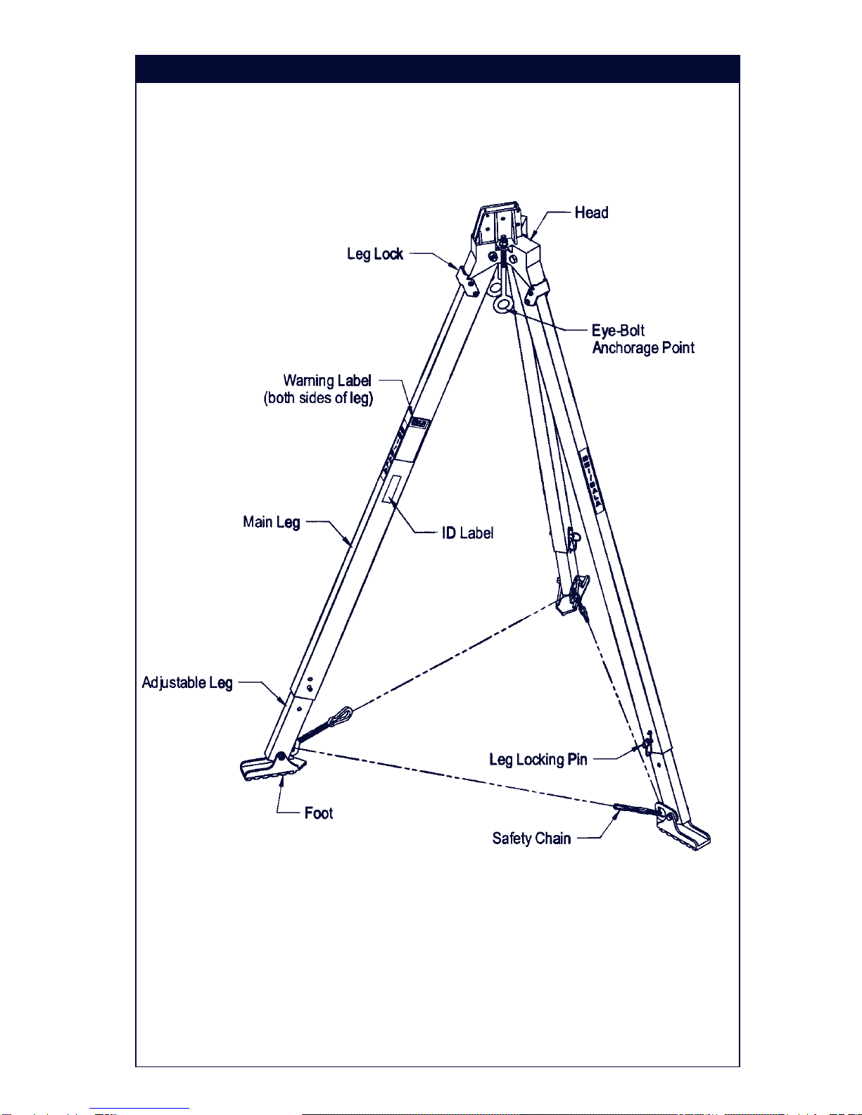
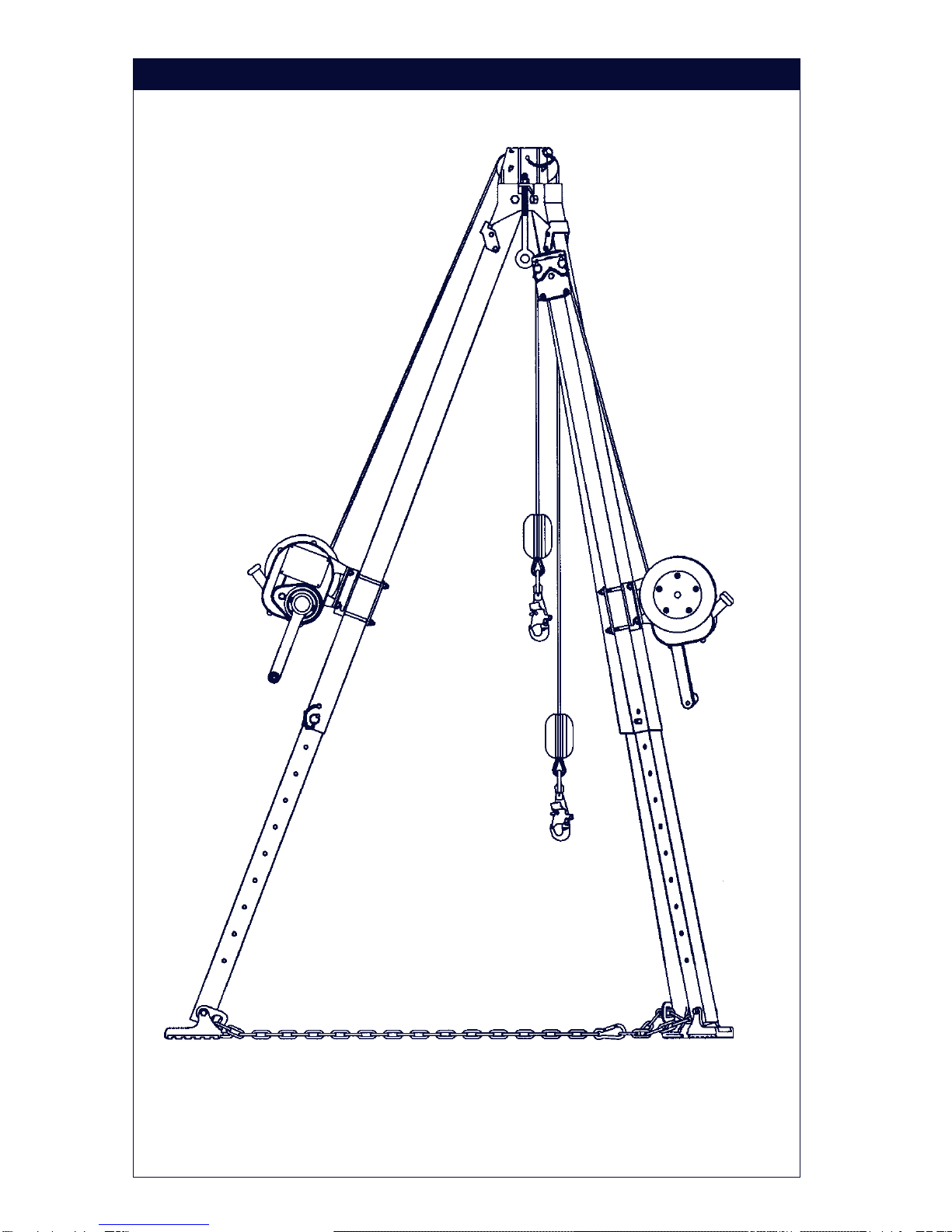
Figure 1
8001717and 8001718 Parts Identification
4
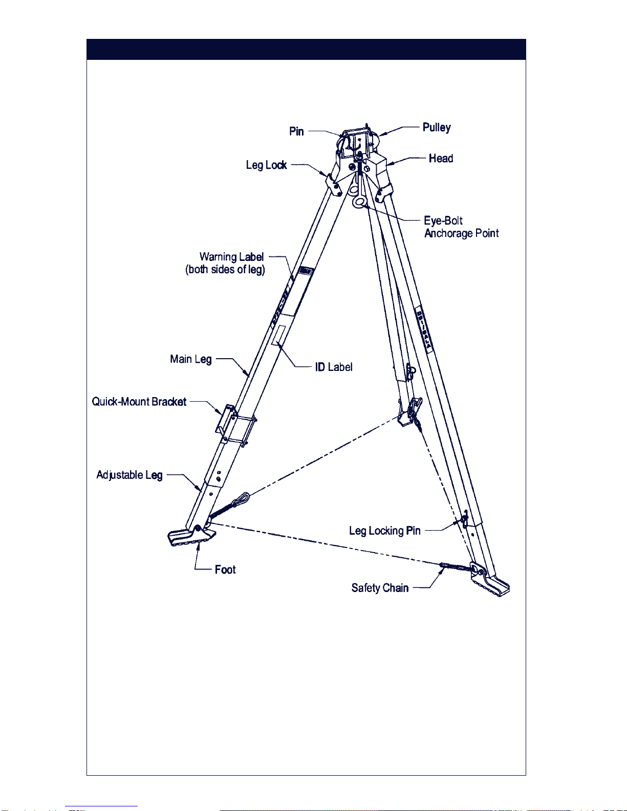
Figure 2
8000000and 8000010 Parts Identification

5
DESCRIPTIONS
8001717 Tripod: 7 ft. maximum height to eye bolt, 5 ft. minimum.Aluminum
construction with adjustable locking legs and safety chains. Fitted rubber
safety shoes with spiked edges.
8001718 Tripod: 9 ft. maximum height to eye bolt, 7 ft. minimum.Aluminum
construction with adjustable locking legs and safety chains. Fitted rubber
safety shoes with spiked edges.
8000000 Tripod: 7 ft. maximum height to eye bolt, 5 ft. minimum.Aluminum
construction with adjustable locking legs and safety chains. Fitted rubber
safety shoes with spiked edges. Includes head mount pulley assembly and
mounting bracket for DBI/SALASalalift® Winch or Self Retracting Lifeline.
8000010 Tripod: 9 ft. maximum height to eye bolt, 7 ft. minimum.Aluminum
construction with adjustable locking legs and safety chains. Fitted rubber
safety shoes with spiked edges. Includes head mount pulley assembly and
mounting bracket for DBI/SALASalalift® Winch or Self Retracting Lifeline.
IMPORTANT: Forspecial(custom) versionsofthisproduct, followthe
instructionsherein.If enclosed, seeattachedsupplement foradditional
instructionstobe followedwhenusing acustomproduct.
1.0 APPLICATIONS
1.1 PURPOSE: DBI/SALAtripods are to be used as part of a work
positioning,personnel riding, personalfallarrest, materialhandling,or
rescue and evacuation system.The tripod is a support structure or
anchorage for these systems.
1.2 LIMITATIONS:Thefollowingapplication limitationsmustbe
consideredbefore using thisproduct.Failure to observeproduct
limitations could result in serious injury or death.
A. INSTALLATION: The tripod mustbeproperly installed in
accordance with the requirements stated in section 3.0 of this
manual.
B. CAPACITY: Themaximum working loadfor this productis 350lbs.
(160kg).
C. PERSONAL FALLARREST SYSTEMS: Personalfall arrest
systems used in combination with the tripod must meet applicable
stateand federalregulations and therequirements insection 3.3.

6
D. PHYSICALAND ENVIRONMENTALHAZARDS: Use ofthis
equipmentin areas containingphysicalor environmentalhazards
mayrequire thatadditional precautionsbe taken to reduce the
possibility of damage to this equipment or injury to the user.
Hazards may include, but are not limited to; high heat (welding
metalcutting); strong orcaustic chemicals; corrosiveenvironments
(seawater);high voltage powerlines; explosive ortoxic gases;
moving machinery; or sharp edges. Contact DBI/SALA if you have
any questions about the application of this equipment in areas
wherephysicalor environmentalhazardsare present.
E. TRAINING:Thisequipment isto be installed and used by persons
who have been trained in its correct application and use.
1.3 Refer to national standards, including; ANSI Z359.1, ANSI A10.14,
ANSI Z117.1, and applicable local, state, and federal (OSHA)
requirements,including 29 CFR1910.146,for moreinformationon the
applicationof thisandassociated equipment.
2.0 SYSTEM REQUIREMENTS
2.1 COMPATIBILITY OF COMPONENTS: DBI/SALAequipmentis
designedfor use withDBI/SALA approvedcomponents and
subsystems only. Substitutions or replacements made with non-
approved components or subsystems may jeopardize compatibility of
equipment and may effect the safety and reliability of the complete
system.
2.2 COMPATIBILITY OF CONNECTORS: Connectorsare considered to
becompatible withconnecting elements whenthey havebeen
designed to work together in such a way that their sizes and shapes
do not cause their gate mechanisms to inadvertently open regardless
of how they become oriented. Contact DBI/SALA if you have any
questionsabout compatibility.
Connectors(hooks, carabiners, andD-rings) mustbecapable of
supportingat least5,000 lbs. (22kN). Connectors must be compatible
with the anchorage or other system components. Do not use
equipmentthat is notcompatible. Non-compatibleconnectors may
unintentionallydisengage.See Figure 3.Connectorsmust be
compatible in size, shape, and strength. Self locking snap hooks and
carabinersare required byANSI Z359.1 andOSHA.
2.3 MAKING CONNECTIONS: Onlyuseself-lockingsnap hooks and
carabiners with this equipment. Only use connectors that are suitable
to each application. Ensure all connections are compatible in size,
7
shape and strength. Do not use equipment that is not compatible.
Ensure all connectors are fully closed and locked.
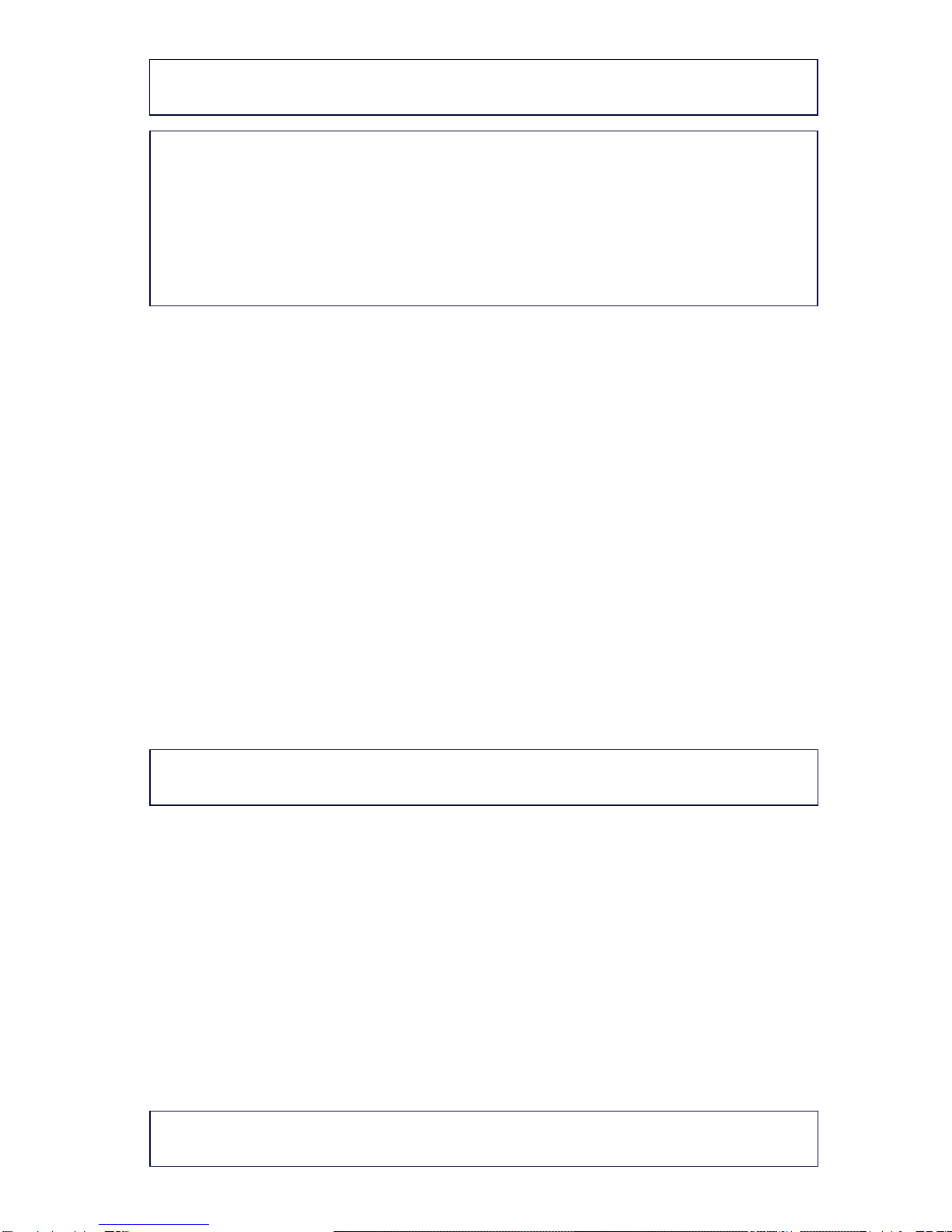
DBI/SALAconnectors (snaphooks and carabiners)are designedto be
used only as specified in each product’s user’s instructions. See
Figure4 for inappropriateconnections. DBI/SALA snaphooks and
carabinersshould not beconnected:
A. To a D-ring to which another connector is attached.
B. In a manner that would result in a load on the gate.
NOTE:Largethroatopeningsnap hooksshouldnotbeconnectedto
standardsize D-ringsor similarobjects whichwill resultina loadon thegate
ifthe hookorD-ring twistsorrotates. Largethroat snaphooksare designed
foruseon fixedstructuralelements suchas rebarorcross membersthatare
not shaped in a way that can capture the gate of the hook.
C. Ina falseengagement, where features that protrudefrom thesnap
hook or carabiner catch on the anchor and without visual
confirmation seems to be fully engaged to the anchor point.
D. Toeachother.
E. Directly to webbing or rope lanyard or tie-back (unless the
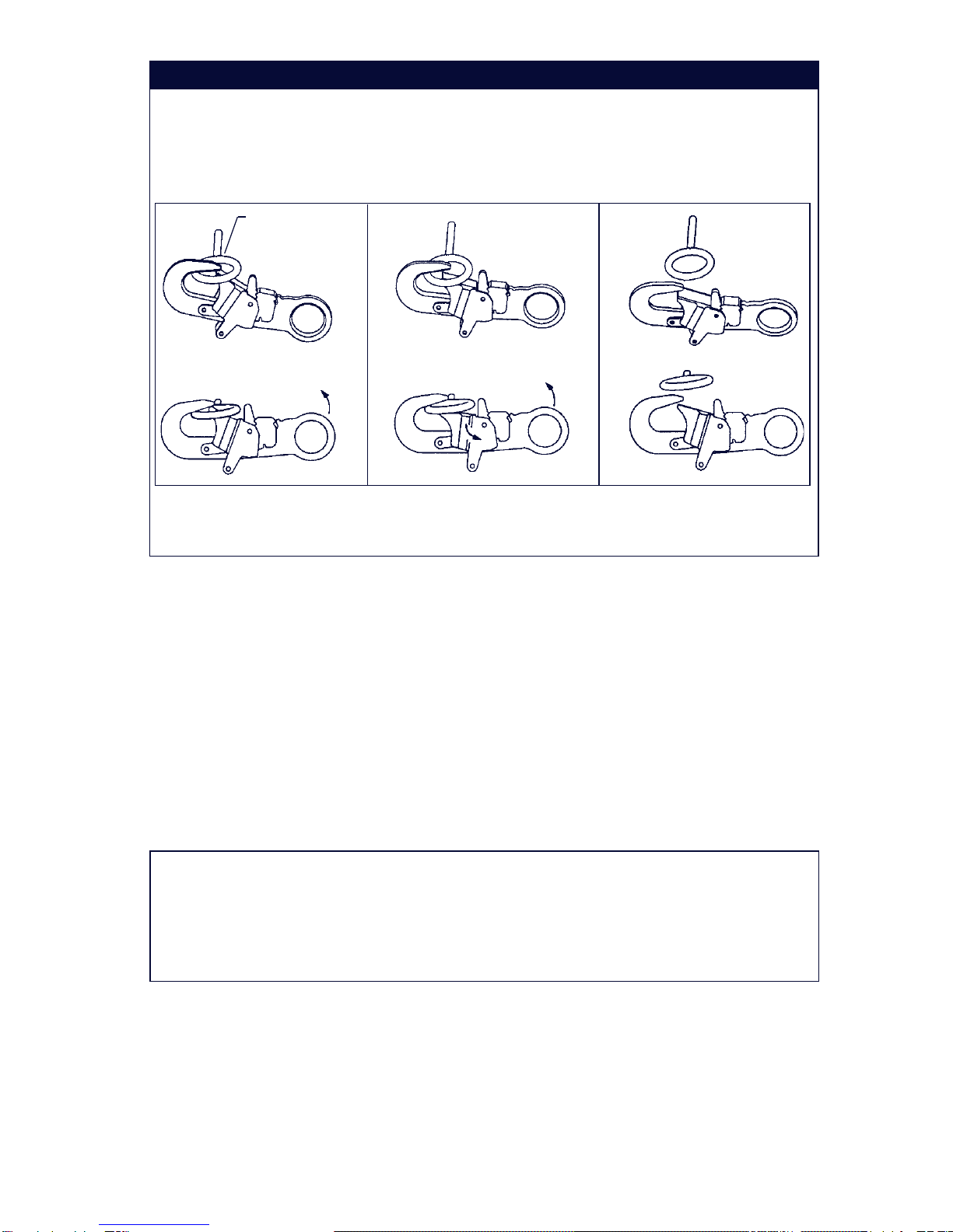
Figure 3 - Unintentional Disengagement (Roll-out)
If the connecting element that a snap hook (shown) or carabiner attaches to is
undersized or irregular in shape, a situation could occur where the connecting
element applies a force to the gate of the snap hook or carabiner. This force may
cause the gate (of either a self-locking or a non-locking snap hook) to open,
allowing the snap hook or carabiner to disengage from the connecting point.
1. Force is applied to
the snap hook. 2. The gate presses against
the connecting ring. 3. The gate opens
allowing the snap
hook to slip off.
Small ring or other
non-compatibly
shapedelement

8
manufacturer’sinstructionsforboth the lanyardand connector
specifically allows such a connection).
F. To any object which is shaped or dimensioned such that the snap
hook or carabiner will not close and lock, or that roll-out could
occur.
2.4 STRUCTURALSTRENGTH: The structure (mounting surface) onto
which the tripod is erected (floor, tank top, roof, etc.) must meet
minimum strengths given below for the applications selected:
FallArrest: FromANSIZ359.1; “The structure(mountingsurface)
selected for personal fall arrest systems (PFAS) shall have a strength
capable of sustaining static loads in the direction(s) permitted by the
PFAS when in use of at least (A) 3,600 lbs. (16kN) when certification
exists (seeANSI Z359.1 for certification definition), or (B) 5,000 lbs.
(22.2kN) in absence of certification. When more than one tripod is
installed on a structure for fall arrest, and the systems will be used
simultaneously, the strengths set forth in (A) and (B) above shall be
multiplied by the number of systems attached to the structure.” From
OSHA1926.500and1910.66;“Anchorages (mounting surface)used
for attachment of personal fall arrest systems (PFAS) shall be
independentof any anchoragebeing usedtosupport orsuspend
platforms, and capable of supporting at least 5,000 lbs. (22.2kN) per
user attached, or be designed, installed, and used as part of a
complete PFAS which maintains a safety factor of at least two and is
underthe supervision ofaqualified person.”
Figure 4 - Inappropriate Connections

9
Work Positioning:Thestructure (mountingsurface)selectedfor work
positioning applications must sustain a static load of at least 5,000 lbs.
applied in the directions permitted by the work positioning system
when in use. Each tripod installation must independently sustain this
load.
Personnel Riding:The structure(mountingsurface) selectedfor
personnel riding applications must sustain a static load of at least
2,500lbs. appliedin the directionspermitted bythe personnel riding
system when in use. Each tripod installation must independently
sustain this load.
Material Handling: Thestructure (mounting surface)selectedfor
material handling applications must sustain a static load of at least
2,500lbs. appliedin the directions permitted by the material handling
system when in use. Each tripod installation must independently
sustain this load.
Rescue: Thestructure(mounting surface) selectedforrescue
applications must be capable of sustaining a static load of at least
2,500 lbs. applied in the directions permitted by the rescue system
when in use. Each tripod installation must independently sustain this
load.
3.0 OPERATION AND USE
WARNING: Do notalterorintentionally misusethisequipment.Consult
DBI/SALAwhen usingthisequipment incombination withcomponentsor
subsystemsotherthanthose describedinthismanual.Some subsystemand
componentcombinationsmay interferewiththe operationof this equipment.
Usecautionwhenusing thisequipmentaroundmovingmachinery,electrical
hazards,chemicalhazards,andsharpedges.
WARNING: Consultyour doctorif thereisreason todoubtyour fitnessto
safelyabsorb theshock fromafall arrest.Age andfitness seriouslyaffect a
worker'sabilityto withstandfalls. Pregnantwomenor minorsmustnot use
theDBI/SALAtripods exceptfor emergencysituations.
3.1 BEFORE EACH USE: Before each useof thisequipment carefully
inspect it to ensure that it is in good working condition. Check for worn
or damaged parts. Ensure all parts (nuts, bolts, etc.) are present and
secure. Check legs to ensure they are straight, free of cracks, dents,
etc. Ensure pulleys rotate freely and entire system is free of corrosion.
Refer to section 5.0 for further inspection details. Do not use if
inspectionreveals anunsafe condition.

10
3.2 PLANNING:Plan your workpositioning,personnelriding, personal fall
arrest,material handling,or rescue andevacuation systembefore
starting your work. Consider all factors that affect your safety at any
timeduring use.Some important pointsto considerwhen planning
your system are:
A. HAZARD EVALUATION: An evaluation ofjob site hazardsis
necessary prior to starting work. Consult applicable OSHAand
industrystandardsfor guidelinesandregulatoryrequirements on
issues such as confined space entry, personal fall arrest
systems, single point adjustable suspended scaffolds, etc.
B. WORK SITE GEOMETRY: The installationand use ofthe tripod
must be consistent with the geometric requirements given in
section3.4 or3.5. When suspendingworking linesfrom the tripod
check for obstructions or sharp edges in the work path.Avoid
working where the user may swing and hit an object or where lines
may cross or tangle with that of another worker in the area.
C. SECONDARYOR BACK-UPFALLARRESTSYSTEM: When
using the tripod as a support for suspending a worker at a work
level,or forpersonnel ridingapplications, asecondary or back-up
fall arrest system is required. See OSHA 29 CFR 1910.28 and
1926.451.Thetripod has provisionsfor connectionof a secondary
or back-up personal fall arrest system. See sections 3.3 and 3.5.
D. RESCUE: In the event of an accident with injuries or other
medical emergency, it is critical that a means of dealing with such
asituation hasbeen plannedin advance.Response timeoften
plays an important role in the survival of an injured worker. Users
ofthis equipment must be trainedin emergency procedures.
3.3 REQUIREMENTS FOR PERSONAL FALLARREST SYSTEMS:
Personal fall arrest systems used with this tripod must meet
applicableOSHArequirements. Whenin use, thePFAS shouldbe
rigged to minimize any potential free fall and never allow a free fall
greater than six feet. It is recommended that the PFAS used with this
equipment include a full body harness as the body support
component.PFAS's that incorporate full bodyharnesses must
maintain fall arrest forces below 1,800 lbs. and arrest the fall within 42
inches. Body belts, unless incorporated into a full body harness, not
recommended for use with this equipment.Atypical PFAS includes a
full body harness, a connecting subsystem or component (self
retracting lifeline or a lifeline and rope grab) and the connectors to
couple the system together.
11
WARNING: Follow themanufacturer'sinstructionsforthe personalfallarrest
equipmentselected foruse withthe tripod.
IMPORTANT: Forfree fallandrescue applications,bodybelts arenot
recommendedforuse. Bodybeltsincrease therisk of injuryduring fallarrest
incomparisonto afullbody harnessanddrastically reducethetolerable
suspensiontimecompared toafullbody harness.Limitedsuspension time,
increasedrisk ofinjury,and thepotentialfor improperlywearing abody belt,
mayresult inadded dangerto theuser.DBI/SALArecommends usinga full
bodyharnessforfall arrestandrescueapplications.
3.4 INSTALLATION REQUIREMENTS OF TRIPOD
A. LOAD REQUIREMENTS: Dependingontheapplication,the
strengthrequirements forthe supporting structureonto whichthe
tripod is erected vary. See section 2.4 for application types and
the supporting structure load requirements. If an installation will be
used for more than one type of application, always select the
loadingfor the applicationwith the greaterloadrequirements.
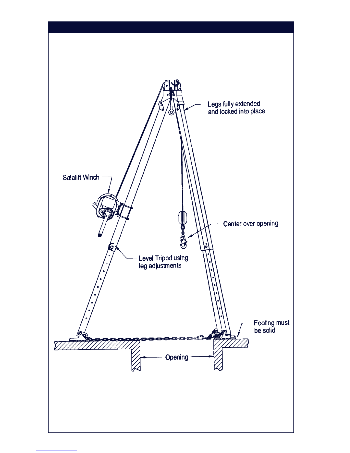
B. GEOMETRIC REQUIREMENTS: Thetripodmustbemounted
where it can be leveled using the leg adjustments. The footing
must be solid under each leg, and support the intended loading.
Position the tripod such that the lifeline will be directly over the
intendedwork area wheninstalled. Do notposition the tripod
where the worker will have to swing under the tripod to reach the
workarea.Avoidpositioningthe tripodwherethe workingline may
abradeagainstsharp edges. SeeFigure5.
WARNING: Neverallow theworking linetoextend outsidethe legsofthe
tripod.Tippingof thetripodcould occur.
C. TO ERECT TRIPOD: The tripod is shipped with the legs set at full
retraction. Erect as follows, see Figure 5: 1) Lay the tripod on the
workingsurface; 2)Adjust legs to requiredworking height;3)Tilt
the tripod into an upright position; 4) Fully spread the legs, ensure
legsare against bearingsurface onhead.Thelegswill
automatically lock in place.To collapse tripod, pull leg down to
disengage leg lock and swing leg in; 5) Position tripod over
opening so working line will be located approximately in the center
of the opening. Ensure footing is solid under each leg and can
support the intended loads. Level the tripod by adjusting the leg
height; 6) Adjust the leg chain by removing excess slack.
WARNING:Exceptforemergencysituationswherelegchainsmayinterfere
withrescue, thetripod mustnever beusedwithout theleg chainsin place.
12
Figure 5
13
Figure 6
Figure 7
IMPORTANT: The tripodmust bepositionedso theworking linewill be
directlyover theintended workarea. Itmust bepositioned toensureasafe
workingareaforthe operator.
WARNING: Do not usethe tripodif oneor more ofthe legsare notlocked
intotheerect position(completely spreadout).
3.5 CONNECTING EQUIPMENT TOTHE TRIPOD: The tripod hasbeen
designed for multi-purpose applications that may involve the use of
one or more systems attached to the tripod.The following details the
connection of equipment to DBI/SALA tripods. See associated
equipmentinstructions for furtherinformation:
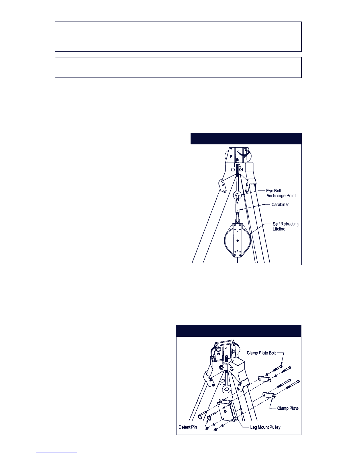
A. EYE-BOLT:Acomponent (self
retractinglifeline,rope grab/
lifeline system) can be
attached to either one of the
eye-boltanchoragepoints.
SeeFigure6.Connect
equipment to the eye bolt
anchoragepoint by usinga
clevis and pin (minimum
breakingstrength of 5,000
lbs.), self locking carabiners or
self locking snap hooks.
B. LEG MOUNT PULLEY:
Figures 7 and 8 shows the
optionalleg mountpulley model 8003238.This pulleyis used
when more than one device is mounted to the tripodlegrequiringa
directionalpulley. The leg mount pulleywill accommodateup to 1/4
inch diameter line. Install the leg mount pulley on the desired
tripod leg as shown in Figure 7. Position the leg mount pulley
directly under the leg lock
near the top of the tripod.
The pulley may be
positionedon either side
of the tripod leg. It may be
necessaryto removeone
of the eye bolts to gain
clearancefor the lifeline.
Tighten the clamp plate
bolts to 15 ft.-lbs. Do not
use or install more than
one system on a single
tripodleg.
14
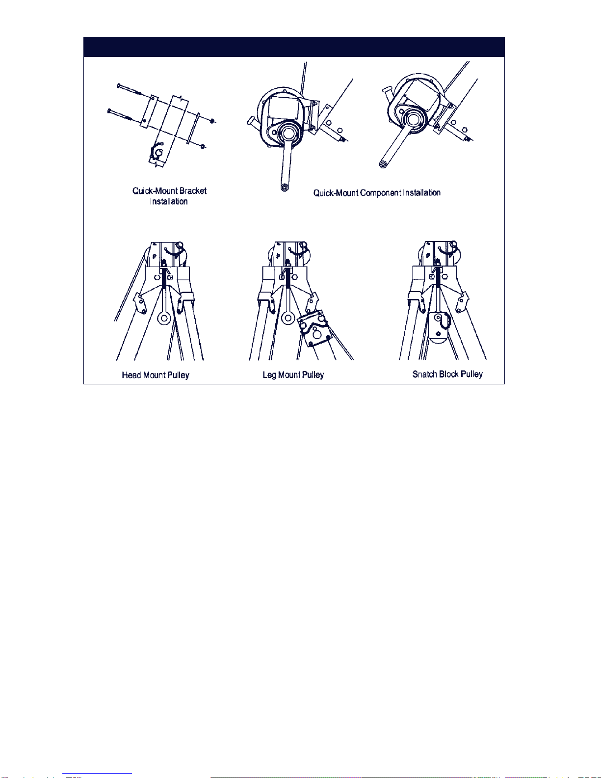
C. QUICK-MOUNT BRACKET: Figure8showsthetripodquick-mount
legbracket8005048(optionalon8001717and 8001718 models).
To install the quick-mount bracket to the tripod leg, assemble as
shown in Figure 8. Adjust bracket to desired position on the leg
and tighten bolts to 15 ft.-lbs. Do not over tighten. Do not install
quick-mountbracket onto thelower (telescoping) leg.The quick-
mount bracket must be used for connection of the Salalift® winch
(8101000series),the WorkWinch(8103000 series) andforleg
mounting of DBI/SALA Self Retracting Lifelines.
D. HEAD MOUNT PULLEYS: The8000000 and 8000010 model
tripodscome equipped withheadmounted pulleys.These pulleys
should be used for mounting the line of the primary use system
overthe tripodheadwhen usedin the legmounted position.The
head mount pulleys will accommodate up to a 1/4 inch diameter
line. See Figure 8, 9, and 10.
E. SNATCH BLOCK PULLEY: Figures8and10 show theoptional
snatch block pulley assembly model 8003205. The snatch block is
used when more than one device is mounted to the tripod
requiring a directional pulley. The snatch block is attached to one
of the unused eye-bolts and will accommodate up to 1/4 inch
diameter line. Do not use the Salalift winch with the snatch block
Figure 8
15
pulley because of possible cable rubbing on the tripod leg, and
uneven winding of the cable onto the winch drum.
F. SALALIFT® WINCH: WhenusingtheSalaliftwinch(8101000
series) with the tripod, the winch must be mounted to the leg
in-line with the head mount pulleys. Route the winch line over the
head mount pulleys as instructed in the Salalift® winch user
instruction manual. Do not use winch with snatch block pulley
(seesection 3.5.E).
WARNING: Multiple systemsmaybe attachedtothetripod (primarysupport
lifelineand back-uplifeline), butthe tripodis forone personuse only.
Exception:Emergencyrescueapplications only.Amaximum ofonesystem
canbe attachedto anyone tripod leg.A maximumof twosystems shouldbe
attachedto onetripod,except back-uplifelines(fallarrest)whichare limited
toone system.
IMPORTANT: Knotsmust notbe used forload-bearing endterminations
(seeANSI Z359.1). Some knots reducethe strength of thelifeline by 50
percentor more.
4.0 TRAINING
4.1 It is the responsibility of the user to assure they are familiar with these
instructions, and are trained in the correct care and use of this
equipment.User mustalso beaware ofthe operatingcharacteristics,
application limits, and the consequences of improper use of this
equipment.
IMPORTANT: Training mustbeconductedwithout exposingthetraineeto a
fallhazard.Training shouldberepeatedona periodicbasis.
5.0 INSPECTION
5.1 FREQUENCY:
•Before Each Use: Visually inspect per steps listed in sections 5.2
and5.3.
•Monthly: A formal inspection of the tripod should be done by a
competent person other than the user. See sections 5.2 and 5.3 for
guidelines. Record results in the inspection and maintenance log in
section 9.0.
•After Fall Arrest: Inspectentiretripodandbasepersection5.2.
16
Figure 9
Two Salalift® Winches Mounted to Tripod
Lifelines routed through Head Mount Pulley and Leg Mount Pulley

17
Figure10
Salalift® Winch and Self Retracting Lifeline Mounted to Tripod
Lifelines routed through Head Mount Pulley and Snatch Block Pulley

18
WARNING: If thetripod hasbeen subjectedto fallarrest or impactforces, it
mustbe immediatelyremovedfrom serviceand inspected.If thetripod fails
topass theinspection, donot use;the equipmentmustbe destroyedor sent
toDBI/SALAforpossible repair.
IMPORTANT: Extremeworkingconditions(harshenvironment,prolonged
use,etc.)mayrequire increasingthefrequencyof inspections.
5.2 INSPECTION STEPS FOR TRIPOD
Step 1. All bolts and nuts must be securely attached. Check for
missing, altered, or substituted bolts, nuts, locking detent
pins or other parts. Inspect the tripod for signs of corrosion
which may weaken or affect parts in their function.
Step 2. Check each leg to see that it can be telescoped in and out
freely. Inspect legs for straightness. Ensure legs lock into
place when tripod is erect.
Step 3. Check the feet on each leg; ensure they pivot and the rubber
pad is in place.
Step 4. Check leg chain and connections; Ensure they are tight and
undamaged, chain must be free of defects and hook must be
inplace and workproperly.
Step 5. Checkthe head. Ensurethe eye-boltanchoragepoints arein
placeand arefree from damage.Ensure thecable pulleysare
cleanandrotate freely (8000000and8000010 modelsonly).
Step 6. Inspect the labels. Ensure all labels are present and fully
legible. See section 8.0.
Step 7. Record the results of inspection in the inspection and
maintenance log in section 9.0 of this manual.
Step 8. Inspect each system component according to manufacturer's
instructions.
5.3 If inspection or operation reveals a defective condition, remove the
tripod from service immediately and contact an authorized service
centerforrepair.
NOTE: OnlyDBI/SALAor parties authorizedin writingmay makerepairs to
thisequipment.

19
ledoMthgieWdaoLgnikroWdetaRlairetaM
7171008.sbl73 krowrof.sbl053 lennosreprogninoitisop ,snoitacilppagnidir tserrallafrof.sbl013 snoitacilppa
yltnanimoderP cnizdnamunimula leetsdetalp
8171008.sbl64
0000008.sbl74
0100008.sbl65
6.0 MAINTENANCE, SERVICING, STORAGE
6.1 Periodically clean the exterior of the tripod using water and a mild
detergentsolution.Clean labels asrequired.
6.2 Replacementparts and additionalmaintenanceand servicing
procedures must be completed by a factory authorized service center.
An authorization and a return number must be issued by DBI/SALA.
6.3 Clean and store the body support and associated system components
accordingto separate instructionsprovided with thatequipment.
6.4 Store this equipment in a cool, dry, clean environment out of direct
sunlight.Avoid areas where chemical vapors may exist. Inspect after
anyperiod of extendedstorage.
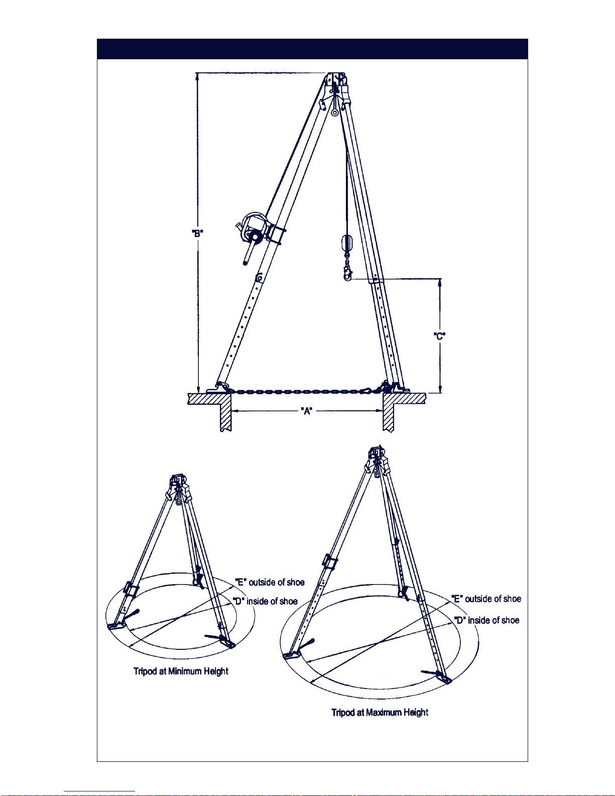
7.0 SPECIFICATIONS
SeeFigure11.
snoisnemiD )11erugiFees(
sledoM.tf7sledoM.tf9
muminiM thgieH )mm(hcni
mumixaM thgieH )mm(hcni
muminiM thgieH )mm(hcni
thgieHmumixaM )mm(hcni
htgneLegarotS)877,1(07----)195,2(201----
retemaideloH* dennaps "A" )485(32)318(23)838(33)811,1(44
thgiehllarevO "B" )727,1(86)263,2(39)314,2(59)840,3(021
thgiehtfilelbaliavA "C" )542,1(94)088,1(47)039,1(67)565,2(101
stnemercnithgieH)67(3----)67(3----
sgelfodaerpS "D"
eohsfoedisnI )811,1(44)006,1(36)156,1(56)431,2(48
sgelfodaerpS "E"eohsfoedistuO )374,1(85)659,1(77)700,2(97)515,2(99
20
* Note: Tripods will span a larger opening; the leg chains will cross
overa portion of the opening.
•These tripods meet ANSI Z359.1, ANSI A10.14, and OSHA
requirements.
•The8000000and8000010 are U.L.classified.Seeproduct label for
details.
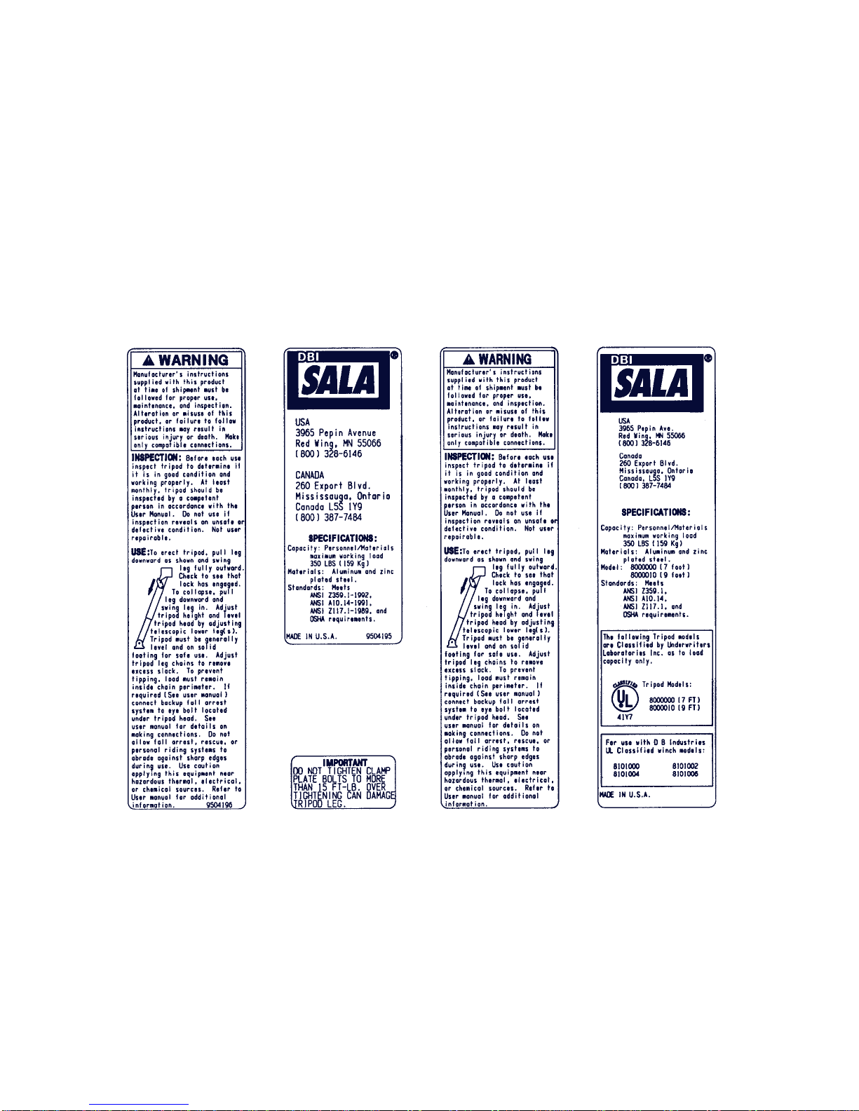
8.0 LABELING
8.1 The following labels must be present and fully legible:
Warning Label
Models8001717
and8001718
Specification Label
Models 8001717 and
8001718
Overtighten
Label Model
1001190
Warning Label
Models8000000
and8000010
Specification
Label Models
8000000and
8000010
21
Figure11
GeometricRequirements
This manual suits for next models
4
Table of contents
Other DBI SALA Camera Accessories manuals


