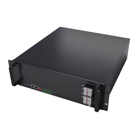
Solar MD mypower24 Operating and maintenance instructions

Solar MD Proprietary Limited
Company Registration: 2014/169938/07
T: 021 555 2181
W: www.mypower24.co.za
1. Specification
2. Product overview
mypower24 3.7k SS106 specification
Battery type
Lithium Iron Phosphate
Scalability
Up to 22 KWh
Battery module
SS106
Communication
CANBUS 500kbps/CAN
2.0B
Rated battery capacity
3.84 kWh
CANBUS termination
Single 120 Ohm
Output power
Max 5 kW
Canbus id range:
256 - 499
Usable battery energy
@0.3C
3.7 kWh
Protection method
Cell level: uv / ov
Nominal voltage
51.2V
Protection phy
Mechanical relay NO
Number of battery modules
1 module
Com isolation
Yes 800V
Weight of MSS
34kg
Transportation
protection
Yes
Operating voltage
44.8V-55.6Vdc
Indicator
Led, programable
Communication
CAN
Addition IO
3 GPO
Dimension enclosure
Albro6: h/w/d
600mm/400mm/200mm
Configuration method
Over mypower24 web
portal
Dimensions of SS106:
h/w/d
500mm/320mm/150mm
Cell balancing
Passive balancing
Net Weight of SS106
35 Kg
Health monitoring
Cycle counters and state
of health
Battery cycle life [+25 ‘C]
> 4000
AUX power output
5V 2A max
Charging efficiency
99%
Storage duration
6 months@+25’C
Operating temperature
-5’C ~+50’C
Safety standard
compliance
IEC 62619/UN
38.3/UL1642
Transport
UN3480 & UN38.3
Cell Certificate
TUV / CE / RCM /
UL1642
IP level
IP65

Solar MD Proprietary Limited
Company Registration: 2014/169938/07
T: 021 555 2181
W: www.mypower24.co.za
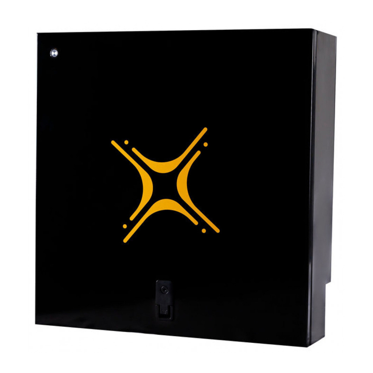
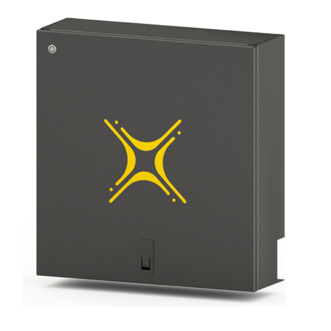
Figure 1 Overview SS106
Position bracket vertically and
slide all the way down until
the limiting notch hit the end.
Tight the screw with big flat
screwdriver.
3. Mechanical installation
3.1.Box bracket assembly
Figure 2 bracket assembly
3.2. Box mounting.
Please use the correct mounting screws for the correct wall surface. The
Battery is only to be installed in upwards position!!!
Figure 3 Dimensions of the wall fixation points.
Figure 4 Installation layout

Solar MD Proprietary Limited
Company Registration: 2014/169938/07
T: 021 555 2181
W: www.mypower24.co.za
3.3. Drilling holes for cable glands and ON/OFF button
Figure 5. Enclosure section bottom view, safe areas for drilling and installation of cable glands.
Please pay attention while drilling, drilling into the cell will cause
internal short circuit, which will cause overheating accompanying with
smoke and risk for damaging nearest cells.
In case accident and fire starts call the fire department immediately.
The only extinguisher that will work on a Lithium-ion Battery fire is a
Class D Fire Extinguisher or Dry Sand or Dry Table Salt.
As shown in Fig 5 the drilling points for the cable glands and switch button.
Example hole 1 is located in front left safe zone for drilling assuming that safe
zone end 55mm from the beginning of the box the center of the hole can be
mark from the bottom of the box by simple calculation end of zone -radius of
the maximum diameter of the gland which normally is gland nut Example with
19mm: from the left side marker is 55-22=33mm from the front side 70-
22=48mm. Hole 2 and 3 with dimension for center hole.

Solar MD Proprietary Limited
Company Registration: 2014/169938/07
T: 021 555 2181
W: www.mypower24.co.za
Figure 6 Top clearance
The top side of the box is clear for drilling
in entire section. Avoid using long drill
bits clearance is 57mm shown in figure 6
4. Electrical installation
Step 1. Before connecting anything be sure that battery is off and the safety
jumper is removed (figure 7 safety jumper).
Figure 7 BMS board component location

Solar MD Proprietary Limited
Company Registration: 2014/169938/07
T: 021 555 2181
W: www.mypower24.co.za
Connecting Inverters/chargers/UPS to the battery unit while is ON
can cause big sparks due to capacitors inside the connected device.
This can be harmful for human.
Connecting main battery terminal must be with right size cable based
on the rated current of the battery the charger/inverter in case it is
lower. Use only 5mm hole diameter for the cable lugs.
Figure 8 connection terminal
Step 2. Connect negative cable to battery negative terminal and positive to
battery positive shown is figure8
Step 3. Install back safety jumper figure7
Step 4. Connect On/Off button to the board connector see figure7

Solar MD Proprietary Limited
Company Registration: 2014/169938/07
T: 021 555 2181
W: www.mypower24.co.za
5. Communication
5.1 Physical connection CANBUS interface devices communicate to each
other over CANBUS interface. This interface contains two pins: CAN
HIGH and CAN LOW. All devices must be connected in parallel see
Figure 9
Only one termination resistor 120 Ohm must be connected for entire
network. Each device has built in termination resistor which can be
activated with jumper. For Bmspl this jumper is located on top of
connector1 see Figure 7. In Figure 9 only Logger has active termination jumper.
Table 1 Connectors pin map
Connector 1(figure7)
Connector 2 (figure7)
Pin
Function
Pin
Function
1
CAN LOW
1
5V aux power supply 2A max
2
CAN HIGH
2
General purpose input1.
3
CAN GROUND
3
General purpose input2.
4
Bat + (51.2) pack voltage
4
General purpose input3.
5
5V aux power supply 2A max
5
General purpose output1.
6
Not connected
6
General purpose output2.
7
Not connected
7
General purpose output3
8
Ground
8
Ground
Figure 9 CANBUS architecture

Solar MD Proprietary Limited
Company Registration: 2014/169938/07
T: 021 555 2181
W: www.mypower24.co.za
Connecting to CANBUS with CAN LOW and CAN HIGH only see table 1.
After successful installation with other devices Canbus status LED should
immediately switch on with green light. To detect correctly that bus is
connected properly BmsPl require to see at least one device on the bus.
Connecting device with same CANBUS ID can cause software issues,
check devices ID before connecting!
Troubleshooting communication.
Canbus status LED
is OFF after
everything is
connected
1. Check that the other devices are switched ON
2. Check that only one termination resistor is enabled
on the bus.
3. Check cable connection of all device on the bus.
Other devices are
losing
communication
after BmsPl has
been connected
1. Check termination resistor. Only one must be
enabled
2.
6. Maximum charging / discharging voltages for not supported devices.
Equalization must be disabled. Please check if your inverter charger has
been approved by Solar MD and it is CAN compatible.
Table 2 Recommended discharge/ charge voltages
Charging
Discharging
Parameter
Value
Parameter
Value
Bulk voltage
54.8V
Low voltage
49V
Float voltage
53.5V
Cut off voltage
47V
This manual suits for next models
1
Table of contents
Other Solar MD Camera Accessories manuals

