Bridge BriPower ESA Series User manual
User manual of ESA Series Power Supply
Product features might be changed by software upgrade. Please acquire the
latest version of the manual from our website or contact technical support.

2
www.bripower.cn
About Bridge Technology
Bridge Technology is a company focusing on business of power supplies and
test systems for new energy applications. We are devoted to providing high
quality products and solutions for customers.
Bridge Technology has a top-class R&D team in China, works on
modularization and standardization power supplies and systems. We have
sales, technical support, R&D and manufacture in Shanghai and Nanjing.
Nanjing Bridge New Energy Technology was founded on Jan 12th, 2016,
focusing on R&D and manufacturing BriPower brand power systems, including
bi-directional AC sources for grid simulation, bi-directional DC sources for
battery simulation, and regenerative loads. The BriPower AC&DC power
systems are widely used in new energy and related fields.
Date and Revision
Sep 2019 Revision 1.0
Contact Information
Factory: Nanjing Bridge New Energy Technology Co., Ltd
Sales Company: Shanghai Bridge Electronic Technology Co., Ltd
General information: [email protected]
Technical Support: [email protected]
Repair &Calibration: [email protected]
Int'l Sales: [email protected]
Tel:+86 40010-18618
Web: www.bripower.cn

3
www.bripower.cn
Summary of Safety Requirement
Please review the following safety precautions carefully before putting
the equipment into operation to avoid any personal injury or damage to
the equipment and any product connected to it. To prevent potential
hazards, please follow the instructions specified in this manual to use
the instrument properly.
Use Proper Cables
Please choose the proper specification cable according to the equipment
specification within the local country could be used.
Ground the Equipment
The equipment is grounded through the Protective Earth Bus. To avoid electric
shock, connect the earth terminal to the Protective Earth terminal before
connecting any input or output terminals.
Use Proper Overvoltage Protection
Ensure that no overvoltage (such as that caused by a bolt of lightning) can
reach the product. Otherwise, the operator might be exposed to the danger of
an electric shock.
Avoid Circuit or Wire Exposure
Do not touch exposed junctions and components when the module is powered
on.
Keep Equipment Surfaces Clean and Dry
To avoid dust or moisture from affecting the performance of the equipment,
keep the surfaces of the equipment clean and dry.

4
www.bripower.cn
Safety Notices and Symbols
Safety Notices in this Manual:
WARNING
Indicates a potentially hazardous situation or practice which, if not
avoided, will result in serious injury or death.
CAUTION
Indicates a potentially hazardous situation or practice which, if not
avoided, could result in damage to the product or loss of important
data.
Safety Terms in this Manual:
Safety Symbols on the Product or in this Manual:
Hazardous Voltage Safety Warning Protective Earth Terminal
Test Ground Chassis Ground
It calls attention to an operation, if not correctly performed, could
result in injury or hazard immediately.
It calls attention to an operation, if not correctly performed, could
result in potential injury or hazard.
It calls attention to an operation, if not correctly performed, could
result in damage to the product or other devices connected to the
product.
DANGER
WARNING
CAUTION

5
www.bripower.cn
Important Safety Instructions
Please read this manual thoroughly before putting the equipment into
operation. Pay regard to the following safety instructions and keep this
manual nearby for future purpose.
INITIAL OPERATION
This operating manual is based on the state of technology at the time of
printing. However, it is possible that despite regular control and correction, the
present document contains printing errors or deficiencies. Nanjing Bridge New
Energy Technology Co.,Ltd assumes no liability for any technical, printing or
translational errors within this manual.
UNPACKING
Please make sure that the shipping carton and the packaging is free of
damage. If external damage is found, it is important to record the type of
damage. Please keep the original packaging to ensure the device is
adequately protected in case it needs to be transported in the future or claims
for compensation need to be asserted.
SETTING UP
To avoid electric shocks and product failure, the device should be installed in a
temperature and humidity controlled indoor environment. The ambient
temperature must not exceed 40℃. The device must never be exposed to
liquids or extreme humidity.
VISUAL INSPECTION
The unit must be examined immediately for defects or damages in transit.
Damage caused during transport may be loose or broken control knobs and
bent or broken connectors. Do not use the device if any physical damage is
apparent. Please inform the carriers and a representative of Bridge
Technology immediately.

6
www.bripower.cn
MAINS OPERATION
Make sure to verify the model number and voltage stated on the nameplate.
Damages due to wrong power feed are not covered by guarantee conditions.
CAUTION
The unit must only be operated when connected directly to the mains.
To avoid damage, do not connect the unit to isolating transformers,
autotransformers, magnetic current limiters or similar devices.
INTENDED USE
The device corresponds to protection class I and has a galvanic isolation
between the input and the output circuit. The device must be grounded on the
input side, since the grounding ensures protection against contact. In the case
of locally variable devices, the earth is connected to the device by means of a
cold-plug connector, and the ground is connected to the screw terminal
provided for locally-variable devices (screw contacts at the grid input). In the
case of devices with high leakage current (marking on the device), the existing
grounding bolt must additionally be connected to the domestic installation
earth. For compliance with the EMC and safety regulations (CE, approvals),
the device may only be operated with PE connected. The device may only be
operated by trained personnel and in accordance with the instructions for use.
Typical fields of application are laboratories, industry and service engineering.
Applications which can lead to injuries or death in the event of a fault in the
device are not permitted.

7
www.bripower.cn
ESA Series Overview
Main Features
➢Single system from 30kVA to 500kVA and parallel up to 4MVA and above
➢Independent three-phase output
➢Voltage and frequency sequencing programming via GUI, slew rate can be
programmed
➢ON and OFF output phase angle can be programmed
➢Current limit can be programmed, output can be shorted for short circuit
test
➢Triger out, TTL signal output for voltage or frequency change
➢LAN/RS485/analog interfaces (standard), RS232 interface (optional)
➢4 quadrant operation, regenerative up to 100% of rated output power back
to grid (-R option)
➢Up to 40th harmonic waveform generation
➢Voltage drop simulation (LVRT for inverter test)
➢RLC load simulation (-RLC option)
➢Regenerative AC load (-LD option)
➢TFT-Touch panel operation
➢Mod-bus/SCPI protocols
➢CE conformity
➢Customized voltage, current and power ranges
➢Emergency stop button
➢Switchable insulation monitoring
➢Output contactor
➢Remote sense

8
www.bripower.cn
Document Overview
Chapter 1 Quick Start
Introduce the appearance, front panel, rear panel user interface as well as
internal structure of power source. In addition, it provides the detailed
procedures of power connection, power-on/off inspection.
Chapter 2 GUI Control Software
Introduce the function and operation method of product’s control software in
detail.
Chapter 3 Remote Control
Introduce how to realize the remote control of the equipment.
Appendix A — Specification of ESA Series Power Supply
List the specifications of ESA series power supply.

9
www.bripower.cn
Contents
Chapter 1 Quick Start ...................................................................................................10
1.1 General Inspection ...............................................................................................11
1.1.1 Inspect the packing ....................................................................................11
1.1.2 Inspect the product.....................................................................................11
1.1.3 Check the accessories...............................................................................11
1.2 Appearance and outline........................................................................................11
1.3 Front Panel ...........................................................................................................12
1.3.1 LCD ............................................................................................................12
1.3.2 Indicator of Status ......................................................................................13
1.3.3 Emergency Stop Button .............................................................................13
The emergency stop button is only used when an unexpected emergency occurs.
Do not press this button in normal working condition.........................................13
1.4 Rear Panel............................................................................................................13
1.5 Internal Structure..................................................................................................14
1.6 Connect to Power.................................................................................................15
1.6.1 Check the input power ...............................................................................15
1.6.2 Check the fuse ...........................................................................................15
1.6.3 Cable selection...........................................................................................15
1.6.4 Connect the AC power ...............................................................................15
1.7 Power on Inspection.............................................................................................17
1.7.1 AC Input power on......................................................................................17
1.7.2 Control module power on...........................................................................17
1.8 User Interface.......................................................................................................19
Chapter 2 Control Software .........................................................................................20
2.1 Setting...................................................................................................................21
2.1.1 Communication parameters.......................................................................21
2.1.2 Protection parameters................................................................................22
2.1.3 Line impedance parameters ......................................................................23
2.1.4 Administrator account.................................................................................24
2.2 Comprehensive Test.............................................................................................24
2.3 Island Test.............................................................................................................26
2.4 Measurement Parameter Monitoring....................................................................27
2.5 Wave Monitoring...................................................................................................29
2.6 Fault Monitoring....................................................................................................30
Chapter 3 Remote Control ...........................................................................................32
3.1 Computer Setting..................................................................................................33
3.2 Software Setting ...................................................................................................34
3.3 Remote Control ....................................................................................................34
Appendix A — Specification of ESA Series ..................................................................35

10
www.bripower.cn
Chapter 1 Quick Start
The contents of this chapter are as follows:
1.1 General Inspection
1.2 Appearance and Outline
1.3 Front Panel
1.4 Rear Panel
1.5 Internal Structure
1.6 Connect to Power
1.7 Power-on/off Inspection
1.8 User Interface

11
www.bripower.cn
1.1 General Inspection
1.1.1 Inspect the packing
If the packaging has been damaged, do not dispose the damaged packaging
or cushioning materials until the shipment has been checked for completeness
and has passed both electrical and mechanical inspection.
The consigner or carrier shall be liable for the damage to the product resulting
from shipment. Factory would not be responsible for free maintenance/rework
or replacement of the product.
1.1.2 Inspect the product
In case of any mechanical damage, missing parts, or failure in passing the
electrical and mechanical tests, contact your local sales representative.
1.1.3 Check the accessories
Please check the accessories according to the packing lists. If the accessories
are damaged or incomplete, please contact your local sales representative.
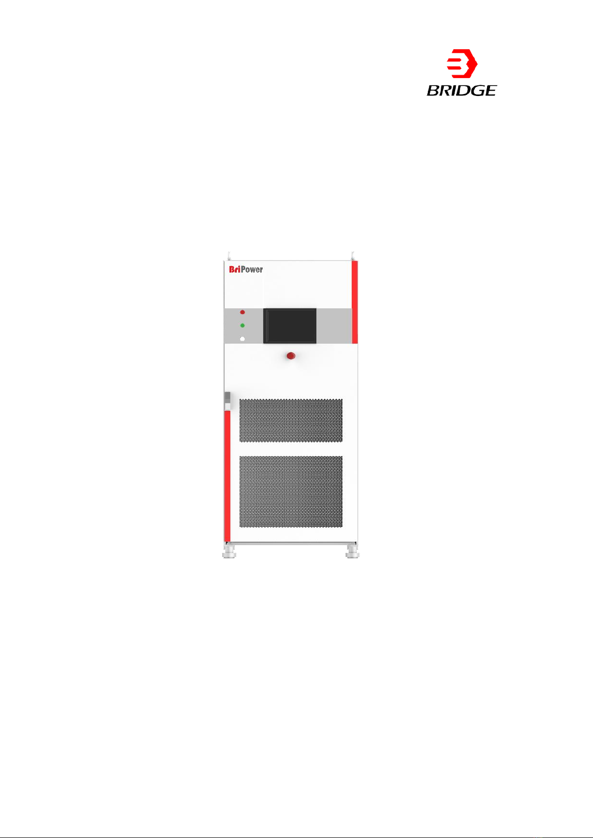
1.2 Appearance and outline
The equipment adopts integrated module design, the appearance is simple
and generous.
The overall appearance of the equipment is shown in Figure 1-1. The cabinet
is equipped with casters, which makes it easier to move. There are a 10-inch
touch screen, status indicators and an emergency stop button on the front
panel. The rear panel is composed of a communication port and a line voltage
drop compensation terminal.
12
www.bripower.cn
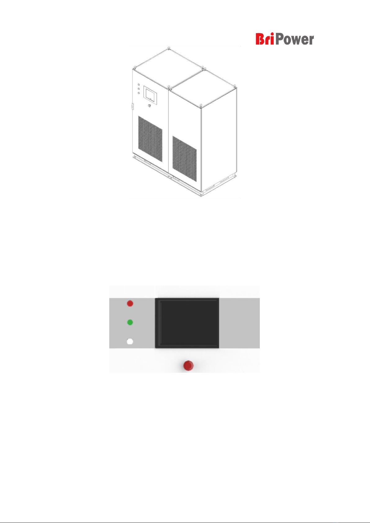
Figure1-1 Appearance of the equipment
1.3 Front Panel
This section introduces the front panel of ESA series power source. The
differences of models are introduced separately.
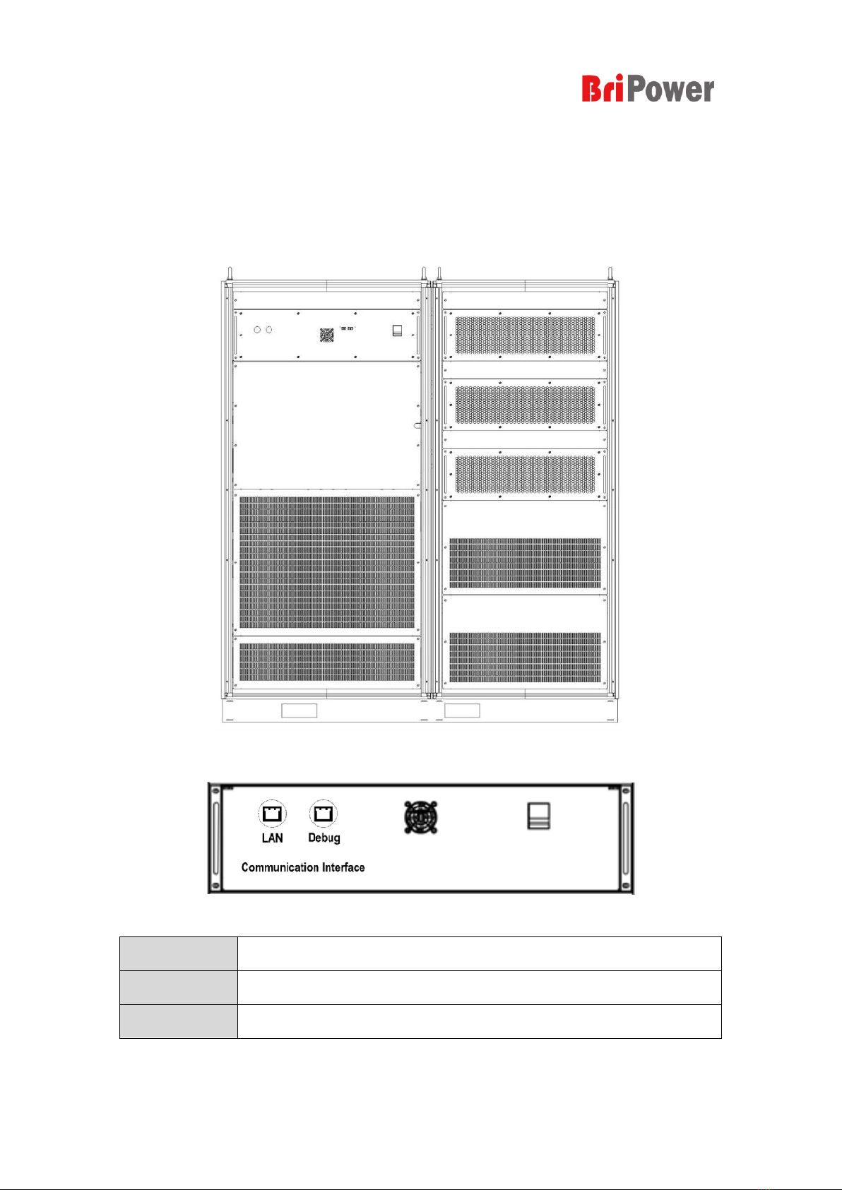
Firgure1-2 Front panel of ESA series
1.3.1 LCD
10 inches TFT display. It is used to display the system parameter setting,
system output state, menu items, prompt messages, etc. The touch displayer
panel is a capacitive touch TFT screen, and is based on Windows operating
system. GUI Control software is designed on the platform of LabView.

13
www.bripower.cn
1.3.2 Indicator of Status
Lights indicate the working state of the power source in a concise manner. It
includes indicator of standby mode, indicator of running and fault indicator.
Red
There is a system error.
Green
System is running normally.
White
System is standby.
1.3.3 Emergency Stop Button
The emergency stop button is only used when an unexpected emergency
occurs. Do not press this button in normal working condition.
1.4 Rear Panel
This section introduces the rear panel of ESA series power source. The
introduction of each part is shown in the following table.
Figure1-3 Rear Panel of ESA Series
LAN
This interface is a communication interface used for remote control.
Debug
The Debug port is reserved for firmware update or debug.
External Sense
Terminal of voltage compensation for long distance.
The output voltages at the load can be directly monitored via the external
sense on the back of the power source, which is usually for long distance
power transfer.
14
www.bripower.cn
1.5 Internal Structure
As shown in Figure 1-4, the left cabinet consists of control module, input circuit
breaker, capacitor output filter, pre-charging resistor and transformer; the right
cabinet consists of power module and output reactor components, etc.
Firgure1-4 Internal Structure
Firgure1-5 Control Module
LAN
This interface is a communication interface used for remote control
Debug
The Debug port is reserved for firmware update or debug
Power Switch
This switch is used to power on the control module.

15
www.bripower.cn
1.6 Connect to Power
ESA series power source supports the world grid standards, but a particular
product supports the GRID SYSTEM only for one country or region. Before the
power supply is used, it is necessary to verify that the product specifications
are consistent with the Local GRID. And please connect the power following
the steps below.
1.6.1 Check the input power
Make sure that specifications of the power source are consistent with the local
GRID, such as voltage and frequency.
1.6.2 Check the fuse
When the product leaves factory, the specified fuse is installed. Please check
whether the fuse matches the actual input voltage according to the "Input
Power Requirements" at the rear panel of the product.
1.6.3 Cable selection
The user should select the appropriate cable and cold-pressed terminal
according to the equipment's input/output voltage level and current, and crimp
the grid side AC input cable and the AC output cable.
1.6.4 Connect the AC power
Connect the power source to AC power supply with proper specification cable
according to the product specification within the local country could be used.
Wiring methods refer to the following steps.
A. Remove the bottom baffle after opening the front cabinet door. The user
can access the grid side incoming line, earthing protection wire PE, the

16
www.bripower.cn
positive and negative poles on the DC side into the cabinet through the
threading holes at the bottom of the cabinet (marked in red in Figure 1-6),
and reliably connect with the terminal/wire copper bar.
Figure1-6 Holes for cables Figure1-7 The wiring copper bar
B. Lay the PE cable from the cable hole at the bottom of the cabinet and
reliably connect with the connection copper bar shown in Figure 1-7, and
ensure both side of PE cable are well grounded. The grounding terminals
are connected with the main components, and the users should connect
them with the earth through suitable cables before putting them into use.
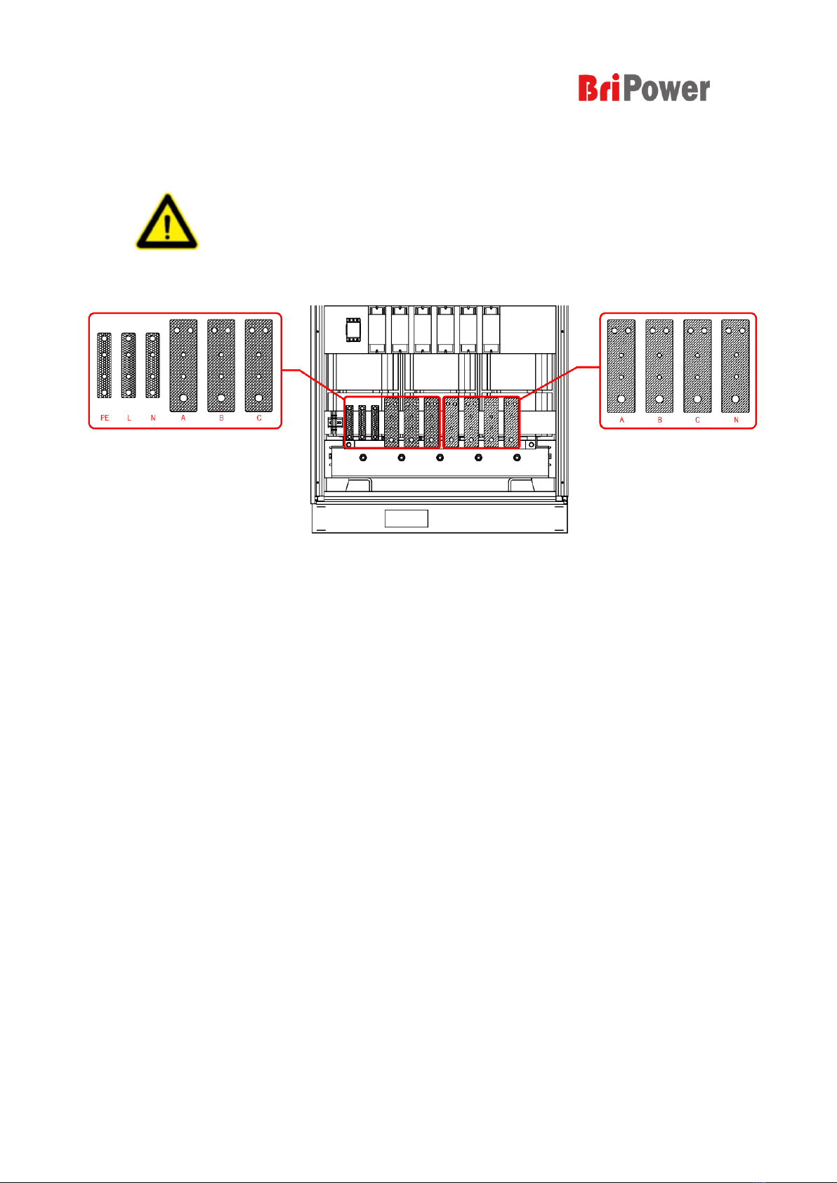
C. The AC incoming line (L1/L2/L3/N) and the positive and negative
terminals/copper bar on the DC side are shown in figure 1-8. After the
cables are threaded through the holes at the bottom, it is connected to the
terminal block/wiring copper bar. After the connection is completed, the
phase sequence and connection reliability should be carefully checked to
Warning
For safety reasons, the grounding protection PE must be
connected reliably.
17
www.bripower.cn
ensure that the phase sequence is correct, the connection is reliable, and
the identification is clear to facilitate maintenance and repair in the future.
Figure 1-8
Connection terminals
1.7 Power on Inspection
1.7.1 AC Input power on
After the cable connection is completed, the circuit breaker on the grid side
could be turned on (as shown in Figure 1-9). It should be noted that the input
connection is 3P+N, and the correct phase sequence must be confirmed.
1.7.2 Control module power on
After power-on for grid side, open the cabinet door, close the power switch of
the control module shown in Figure 1-10 (②), then the control unit starts to
work. After completing these operations, close the cabinet door, and the power
supply will enter standby state.
Warning
Before connecting the cable, make sure that the upper switch is in
the off state. Live work is strictly prohibited. At the same time,
ensure that a reliable protective grounding has been made.

18
www.bripower.cn
Figure1-9 Connection of Mains and DUT
配电网
断路器
2
1
Figure 1-10 Power on the Control module

19
www.bripower.cn
1.8 User Interface
The GUI software is installed in the touch panel, which is in fact a computer
with Microsoft Windows. The software can also be installed in control PC
connected to power supply. The GUI software provides functions including
output settings, island test settings, protection parameter settings, waveform
display, measurement display and faults display.
Also, the power source can be controlled in local and remote style. Both of
which have same interface and operation. The modes will be described in
Chapter 2.
While the Power knob is turn on, it takes several seconds to initialize the
controller and other units. Make sure that the power’s output connection
terminals are correctly connected. Then, All the functions and parameters can
be set and run via touch panel displayer or GUI software.

20
www.bripower.cn
Chapter 2 Control Software
The contents of this chapter are as follows:
2.1 Setting
2.2 Comprehensive Test
2.3 Island Test
2.4 Measurement Parameter Monitoring
2.5 Wave Monitoring
2.6 Fault Monitoring
Other manuals for BriPower ESA Series
1
Table of contents
Other Bridge Power Supply manuals

Popular Power Supply manuals by other brands


MSA
MSA UNICONT PS-203-40 operating manual

Chauvin Arnoux
Chauvin Arnoux PA30W user manual

Extron electronics
Extron electronics P/S 150 user guide

TDK-Lambda
TDK-Lambda HWS ME Series instruction manual

Raycap
Raycap PowerPlus System 100-3-1U Series Installation instructions operations manual

V-TAC
V-TAC VT-606 instruction manual


