MSA UNICONT PS-203-40 User manual

“NPK Morsvyazavtomatica”LLC”
Russia, 192174 Fax: +7 (812) 362-76-36 www.unicont.com
POWER SUPPLY UNIT
PS-203-40
Operating manual

Operating manual
Version 1.0 Page 2
Table of contents
INTRODUCTION.........................................................................................................................3
1DESCRIPTION AND OPERATION OF THE PRODUCT...............................................4
1.1 Description............................................................................................................................4
1.2 Technical specifications........................................................................................................4
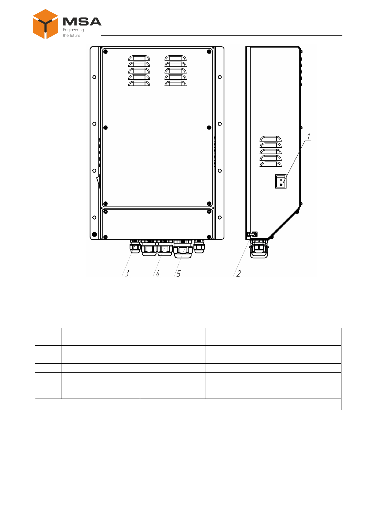
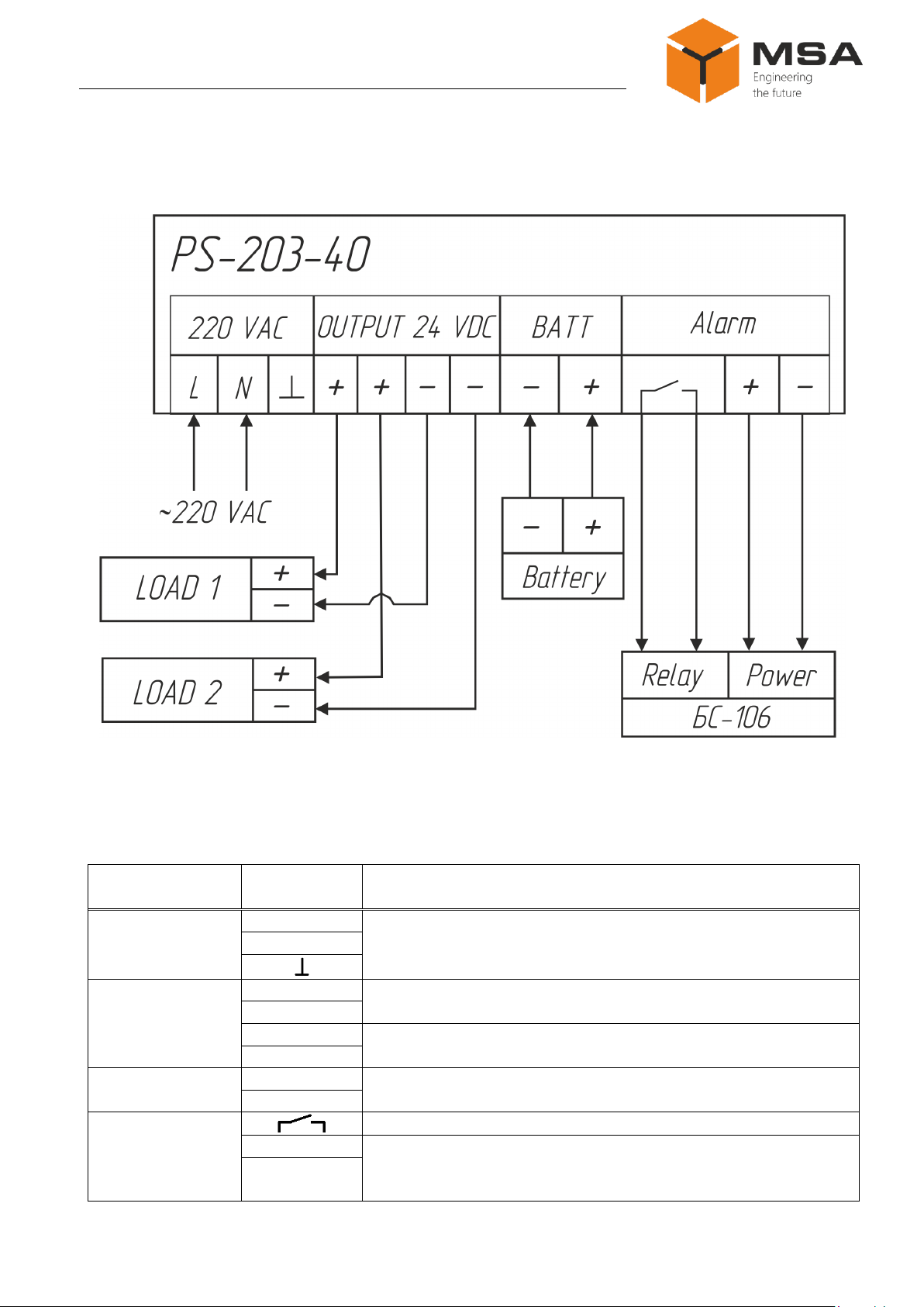
1.3 Structure and operation of the Product..................................................................................4
1.4 Measurement instruments, tools and appliances...................................................................7
1.5 Marking and sealing..............................................................................................................7
1.6 Packaging..............................................................................................................................7
2INTENDED USE OF THE PRODUCT................................................................................8
2.1 Operational limitations..........................................................................................................8
2.2 Usage preparations................................................................................................................8
3TECHNICAL SERVICE OF THE PRODUCT.................................................................10
3.1 General description .............................................................................................................10
3.2 Safety features.....................................................................................................................10
3.3 Maintenance routine............................................................................................................10
3.4 Preservation.........................................................................................................................11
4CURRENT REPAIR OF THE PRODUCT........................................................................12
4.1 General description .............................................................................................................12
4.2 Safety features.....................................................................................................................12
4.3 Current repair ......................................................................................................................12
5STORAGE.............................................................................................................................13
6TRANSPORTATION...........................................................................................................14
7DISPOSAL.............................................................................................................................15
8WARRANTY.........................................................................................................................16
APPENDIX A (MANDATORY) REGULATORY DOCUMENTS ......................................17

Power supply unit
PS-203-40
Page 3 Version 1.0
INTRODUCTION
This operating manual (hereinafter –OM) describes composition, structure, op-
eration and technical service of power supply units PS-203-40 type (hereinafter –the
Product).
In addition to the instructions given in this document, the safety regulations and
rules applicable in the field shall be observed.
Only those who have read and understood this document and those who have
had special training shall be permitted to operate the Product according to the applicable
regulations.
TERMS AND ABBREVIATIONS:
OM –operating manual;
SC –short circuit;
TS –technical service;
CL –check list;
PS-203-40 –power supply unit PS-203-40.

Operating manual
Version 1.0 Page 4
1DESCRIPTION AND OPERATION OF THE PRODUCT
1.1 DESCRIPTION
The Product operates with single-phase AC, frequency 50 (60) Hz, voltage
110 V or 220 V. It powers different shipborne and industrial equipment with regulated
voltage 24 V DC. The PS-203-40 has a function of load switch to standby power.
1.2 TECHNICAL SPECIFICATIONS
Table 1 describes technical specifications of the Product.
Table 1 –General technical specifications
Parameter
Value
Input supply voltage, AC, frequency
50 (60) Hz, V
110 (90 to 132)*
220 (180 to 264)*
Consumption current, A
10 (115 V, 47 to 63 Hz)
6 (230 V, 47 to 63 Hz)
Rated output voltage, DC, V
24
Load current, А
40 (max. 37.5)
Power consumption, W
1163
Output power, W
1000
Pulses, mV
200
Efficiency, %
86
Number of load terminals, pcs.
2
Protection degree
IP22
Operating temperature, °С
–15 to +55
Limiting temperature, °С
–60 to +70
Weight, kg
8.56
Integrated protection
Galvanic isolation of input and output power circuits
SC and overload
Mounting
wall
* Supply voltage range is given in parenthesis.
1.3 STRUCTURE AND OPERATION OF THE PRODUCT
1.3.1 The Product is manufactured in metal casing, which has a mounting to
vertical bulkhead. A piano type on/off switch with a main power LED (green) is located
on the casing side. The LED operates when the switch is turned to power “ON”posi-
tion (Figure 1).

Power supply unit
PS-203-40
Page 5 Version 1.0
Figure 1 –The Product
Table 2 describes functional elements and controls of the Product.
Table 2 –Functional elements, controls and LED light indicators of the Product
№
Element
Type, size, identifi-
er
Description
1
Piano type switch
–
Piano type switch to switch on/off power,
with backlight
2
Grounding stud
М5х20
Main grounding element
3
Cable gland
MG-16
Cable gland to connect input and standby
power, loads and alarm
4
MG-25
5
MG-32
Note –See positions (№) in Figure 1.
1.3.2 Power from standby sources or SB is supplied to the Product terminals
ensuring uninterruptible operation of the equipment connected to the Product, see Fig-
ure 2.
Automatic standby power switching occurs in case of the Product failure and
main power failure. If there is no input power, dry contacts relay actuates alarm signal-

Operating manual
Version 1.0 Page 6
ing. SB voltage to power external signaling unit AU-106 (AU-206) is connected to
“Alarm”terminal.
Table 3 describes assignment of connector terminals.
Figure 2 –Connection diagram
Table 3 –Assignment of PS-203-40 connector terminals
Connector
Terminal
№
Description
220 V AC
L
To connect main power
N
OUTPUT
24 V DC
+
To connect load 1
-
+
To connect load 2
-
BATT
+
To connect external SB
-
Alarm
To connect relay contacts AU-106 (AU-206)
+
Power 24 V or 12 V DC
-

Power supply unit
PS-203-40
Page 7 Version 1.0
1.4 MEASUREMENT INSTRUMENTS,TOOLS AND APPLIANCES
Table 4 below describes consumables required for the TS.
Table 4 –Consumables required for the TS
Name and identifier of consumables
Amount of
consumables
Note
Cleaning cloth
0.10 kg
1To clean the Product surfac-
es –use clean cloth
2To remove severe contami-
nation –use cloth soaked in
alcohol
Rectified hydrolytic technical ethyl alcohol
0.05 l
To soak cloth when removing
contamination from a screen
Varnish
0.05 kg
To cover surfaces of the Prod-
uct in case of paint coating
damage
Abrasive cloth
0.06 х 0.06 m
To polish surfaces of the Prod-
uct in case of paint coating
damage
1.5 MARKING AND SEALING
The Product has a nameplate displaying a name, input and output voltage, power
consumption and output power, protection degree, weight, serial number and date of
manufacturing.
Sealing of the Product is not provided.
1.6 PACKAGING
When delivered, the Product is packed in a corrugated board box and inner
packaging (air bubble film) ensuring its transportation and storage at the warehouse.
Transport packaging is also used as a returnable packaging for transportation of
the Product to the repair location and back.
Sealing of packaging is not provided.

Operating manual
Version 1.0 Page 8
2INTENDED USE OF THE PRODUCT
2.1 OPERATIONAL LIMITATIONS
Select an installation place in compliance with operational limitations (operating
temperature and protection degree).
Caution! Distance between the installation site and magnetic compass
shall not be less than 1 m!
2.2 USAGE PREPARATIONS
2.2.1 Safety features
While preparing the Product for operation, check it visually and make sure there
is no mechanical damage.
Connect the Product to power mains only in compliance with input power re-
quirements.
Before connection the Product shall be switched off and grounded.
While using the Product the staff shall follow “The technical rules for operation
of electric installation”and “Safety rules for operation of electric installation”while
testing electrical circuits and insulation resistance.
2.2.2 Visual check procedure
Before switching the SC on, the installer shall:
a) observe visually the cable integrity and initial position of the controls;
b)clean the SC from dust and dirt by clean soft cloth, if necessary, see Table 4;
c) check fail-safe cable connections to the SC and their proper grounding.
2.2.3 Instructions on powering the Product. While connecting the Product and
preparing it for operation follow the steps below:
a) transfer circuit breakers of main power switchboard to “OFF”position;
b)connect de-energized power cable to input terminals;
c) transfer the circuit breakers of main power switchboard to “ON” position;
d)transfer a piano type switch “ON/OFF” on the casing to “ON”position;
e) check the Product connection; check main power supply by green LED on the
piano type switch; make sure there is no alarm on dry contacts;

Power supply unit
PS-203-40
Page 9 Version 1.0
f) using voltmeter, measure output voltage on connectors’ contacts (for load
connection); measured values shall be 24 V DC. If measured voltage is different from
the rated value, the Product is not ready for operation. Contact the Manufacturer;
g)transfer piano type switch to “OFF”position and connect the load;
h)switch the Product on and check operation of load.
2.2.4 To switch the Product off:
a) switch off the load (only if a load may be switched off by a switch located on
the load casing; in another case, a load switches off once the Product power is turned
off);
b)transfer the piano type switch “ON/OFF”on the casing to “OFF”position,
and then transfer circuit breakers of main power switchboard to “OFF”position.

Operating manual
Version 1.0 Page 10
3TECHNICAL SERVICE OF THE PRODUCT
3.1 GENERAL DESCRIPTION
Before performing the TS the staff shall familiarize with the Product structure
and operation features.
In order to provide safe and reliable operation for the Product, the staff shall
maintain semi-annual TS.
ТS is carried out on the equipment in operation.
3.2 SAFETY FEATURES
While providing TS the staff shall follow instructions, see 4.2.
3.3 MAINTENANCE ROUTINE
The list of works for all types of the TS is given in Table . Maintenance routine
procedure is described in the CL, represented in Tables 6, 7.
Table 4 describes consumables required for the TS.
Table 5 –TS works
CL №
Name of work
TS
1
Visual check of the Product
+
2
Test of output voltage
+
Note –“+”–work is obligatory.
Table 6 –CL № 1. Visual check
To be done
Routine
Man-hours
per 1 Prod-
uct
Visually examine the Prod-
uct
1 Check completeness and appearance of the Product; me-
chanical damage, paint defects must be absent; marking
plates shall be present; legends shall be read easily
2 Clean up the Product surfaces with clean cloth
3 Remove severe contamination, parts of corrosion, oil
spots from the metal surfaces –using ethyl alcohol, avoid-
ing its penetration inside the Product; all surfaces clean dry
by clean cloth and dry up
4 If varnish paint coating is damaged, polish it with sand
paper, then clean with alcohol-soaked cloth, cover with
varnish and dry up
1 person
5 mins
Check reliability of cable
and bus connection to the
Product
1 Check that connectors and attaching screws are tight-
ened; provide further tightening if necessary
2 Check the cable intactness (no mechanical damage) with-
in visibility
1 person
5 mins

Power supply unit
PS-203-40
Page 11 Version 1.0
Table 7 –CL №2. Test of output voltage
To be done
Routine
Man-hours
per 1 Prod-
uct
Test of output voltage
1 Switch on the Product power supply
2 Connect a voltmeter to output terminals of the Product
3 Supply power to the Product
4 Measure voltage on the output terminals
1 person
15 mins
3.4 PRESERVATION
The Product and set of operational documents are stored in preserved condition
in Manufacturer’s packaging boxes.
Time of represervation –2 years since the date of packaging at the Manufac-
turer’s plant.
The preservation is done in full terms, for 2 years, applying protection and pack-
aging.
The represervation is done in heated rooms in the same order as the preser-
vation.
The Product after represervation and documents are placed in packaging.

Operating manual
Version 1.0 Page 12
4CURRENT REPAIR OF THE PRODUCT
4.1 GENERAL DESCRIPTION
To provide diagnostics of the problems, see Table 8.
If a problem cannot be diagnosed or trouble shooting cannot be provided, con-
tact the Manufacturer’s service center.
4.2 SAFETY FEATURES
Only qualified personnel, examined in occupational safety may perform repair
works.
The Product must be grounded before repair works. Check the grounding of the
Product.
It is PROHIBITED to put a poster “DO NOT switch on! Under Operation!”,
when power supply switch is in “OFF”position.
Replacing defected parts, cards and modules when power of device under repair is
ON is STRICTLY PROHIBITED
Installation, commissioning and repair works are PROHIBITED in the room, where
less than 2 people present
4.3 CURRENT REPAIR
The service personnel can provide repair works as given in Table 8.
Table 8 –Possible problems/defects and troubleshooting
Problem/defect
Possible reasons
To do
Piano type LED does
not operate (no glow-
ing)
No power supply
Check power cable connection
Provide power supply (circuit breaker of main
power switchboard might be switched off)
Circuit breaker switched
off
Take off casing panel and switch on the cir-
cuit breaker inside the casing

Power supply unit
PS-203-40
Page 13 Version 1.0
5STORAGE
The Product must be stored in packaging inside areas complying with the re-
quired storage conditions (+5°С to +40°С) with the concentration of dust, oil, moisture
and aggressive impurities in the air within the required limits for the working areas of
production facilities.
After storage or transportation of the Product below +10°С, it must be un-
packed only in heated premises and left in normal climate conditions for 12 hours be-
forehand.

Operating manual
Version 1.0 Page 14
6TRANSPORTATION
The Product must be transported in the Manufacturer's transportation package in
closed means of transport.
Types of shipment:
- motor vehicle and railroad transportation in closed means of transport (covered
cars, multipurpose containers);
- air transportation (in sealed and heated compartments);
- sea transportation (in dry service spaces).
The Product must be transported in compliance with transportation rules appli-
cable for each means of transport.
During loading/unloading operations and transportation, the requirements indi-
cated on warning labels on the boxes/packaging must be observed, and no impacts are
permitted since they can affect the safety and performance of the Product.
Inside the means of transport, the packed device must be firmly se-
cured/fastened.

Power supply unit
PS-203-40
Page 15 Version 1.0
7DISPOSAL
New equipment, the parts of the Product damaged during operation, and any
outage equipment must not be disposed as standard household wastes, since they con-
tain the materials suitable for re-use.
Decommissioned and non-used components of the Product must be delivered to
a special waste disposal center licensed by local authorities. You can also send an over-
age equipment/unit to the manufacturer for its further disposal.
Proper disposal of Product components allows avoiding possible negative envi-
ronmental and health impacts, and it also allows for proper restoration of components
with substantial energy and resources saving.
During operation and upon completion of its service life, the equipment is not
hazardous for health and environment
This unit must be disposed according to the rules applied to electronic devices
Any products marked with a crossed trash bin must be disposed sepa-
rately from standard household wastes

Operating manual
Version 1.0 Page 16
8WARRANTY
The Manufacturer is under warranty obligations in case of correct System ex-
ploitation according to the OM. The Manufacturer will not consider damage claims in
case of violation of operating conditions.
More information about warranty terms you can find on the official site of
“NPK MSA” LLC, section Support.
Address and contacts of the Manufacturer's service centre:
“NPK MSA”, LLC
26E, Kibalchicha str., 192174, St Petersburg, Russia
Tel.: + 7 (812) 602-02-64, 8-800-100-67-19
fax: +7 (812) 362-76-36
e-mail: serv[email protected]om

Power supply unit
PS-203-40
Page 17 Version 1.0
APPENDIX A
(MANDATORY)
REGULATORY DOCUMENTS
Figure A.1 –Outline and installation dimensions of the Product
Table of contents
Other MSA Power Supply manuals