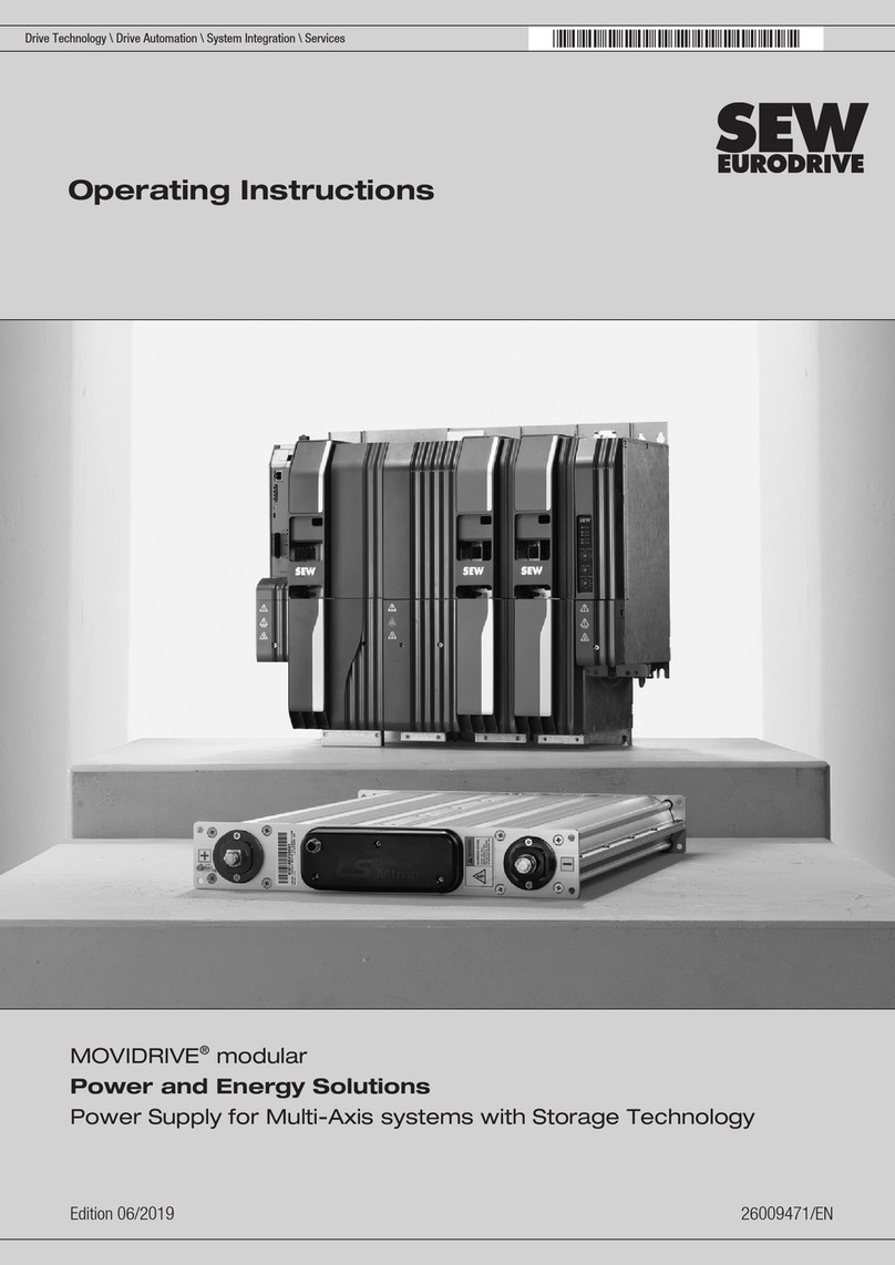
SEW-Eurodrive MOVIDRIVE MDR60A User guide

Gearmotors \ Industrial Gear Units \ Drive Electronics \ Drive Automation \ Services
MOVIDRIVE
®
MDR60A
Regenerative Power Supply Unit
S
ystem
M
anual
EA363000
Edition 02/2006
11369612 / EN

SEW-EURODRIVE – Driving the world

System Manual – MOVIDRIVE® MDR60A Regenerative Power Supply Unit
3
1 Important Notes...................................................................................................... 5
2 System Description................................................................................................ 7
2.1 Two types of DC link connection..................................................................................7
2.2 DC link connection without regenerative power supply unit.........................................8
2.3 DC link connection with regenerative power supply unit..............................................9
3 Technical Data and Dimension Drawings.......................................................... 11
3.1 CE marking, UL approval and unit designation..........................................................11
3.2 General technical data...............................................................................................13
3.3 MOVIDRIVE®MDR60A0370-503-00.........................................................................14
3.4 MOVIDRIVE®MDR60A0750-503-00.........................................................................16
3.5 MOVIDRIVE®MDR60A1320-503-00.........................................................................18
3.6 Line choke option type ND.........................................................................................20
4 Project Planning................................................................................................... 22
4.1 DC link connection without regenerative power supply unit.......................................22
4.2 DC link connection with regenerative power supply unit............................................26
4.3 Selecting the braking resistor BW.../ BW...-T / BW...-P .............................................32
5 Installation (MDR60A0370/750)........................................................................... 36
5.1 Installation notes........................................................................................................36
5.2 EMC-compliant installation.........................................................................................38
5.3 UL compliant installation............................................................................................38
5.4 Wiring diagrams.........................................................................................................39
6 Startup (MDR60A0370/0750)................................................................................ 42
6.1 Evaluation of the ready signal....................................................................................42
6.2 Parameter setting P52_ "Power off control"...............................................................44
7 Operation and Service (MDR60A0370/0750)...................................................... 45
7.1 Reset..........................................................................................................................45
7.2 Operating characteristics ...........................................................................................46
7.3 SEW electronics service ............................................................................................47
8 Introduction (MDR60A1320-503-00).................................................................... 48
8.1 Scope of delivery .......................................................................................................48
8.2 Legal provisions.........................................................................................................49
9 Safety Notes (MDR60A1320-503-00)................................................................... 51
9.1 General safety notes..................................................................................................53
9.2 Persons responsible for safety...................................................................................55
9.3 Designated use..........................................................................................................55
9.4 Layout of safety notes................................................................................................56
9.5 Residual dangers.......................................................................................................56
9.6 General information ...................................................................................................57

4
System Manual – MOVIDRIVE® MDR60A Regenerative Power Supply Unit
10 Technical Data (MDR60A1320-503-00) ............................................................... 62
10.1 General technical data...............................................................................................62
10.2 Rated data .................................................................................................................63
10.3 Current carrying capacity...........................................................................................63
10.4 Fuses and cable cross sections.................................................................................64
11 Installation (MDR60A1320-503-00)...................................................................... 65
11.1 Mechanical installation...............................................................................................65
11.2 Notes on electrical installation....................................................................................66
11.3 Electrical connection..................................................................................................67
11.4 Installation in a CE typical drive system.....................................................................72
12 Startup (MDR60A1320-503-00)............................................................................ 74
12.1 Initial operation...........................................................................................................74
12.2 Ready signal ..............................................................................................................74
13 Configuration (MDR60A1320-503-00)................................................................. 75
13.1 Important notes on configuration ...............................................................................75
14 Operation and Service (MDR60A1320-503-00)................................................... 77
14.1 Reset..........................................................................................................................77
14.2 Operating displays .....................................................................................................78
14.3 Maintenance ..............................................................................................................80
15 Index of Changes ................................................................................................. 81
15.1 Changes to the previous version ...............................................................................81
16 Index...................................................................................................................... 82

System Manual – MOVIDRIVE® MDR60A Regenerative Power Supply Unit
5
1
1
2
3
4
5
6
7
8
9
10
11
12
13
14
15
16
17
18
19
20
21
22
Important Notes
Systemhandbuch
1 Important Notes
Safety and
warning notes
Always observe the safety and warning instructions in this publication.
A requirement of fault-free operation and fulfillment of any rights to claim under guar-
antee is that you adhere to the information in the operating instructions. Read the
operating instructions before you start operating the unit!
The operating instructions contain important information about service and should
be kept near the unit.
Designated use
MOVIDRIVE®units have been designed for stationary installation in control cabinets.
Observeall information on the technical data andthe permittedconditions wherethe unit
is operated.
Do not start up the unit (take it into operation in the designated fashion) until you have
established that the machine complies with the EMC Directive 89/336/EEC and that the
conformity of the end product has been determined in accordance with the Machinery
Directive 98/37/EEC (with reference to EN 60204).
Electrical hazard
Possible consequences: Severe or fatal injuries.
Hazard
Possible consequences: Severe or fatal injuries.
Hazardous situation
Possible consequences: Slight or minor injuries.
Harmful situation
Possible consequences: Damage to the unit and the environ-
ment.
Tips and useful information.
MOVIDRIVE®units are intended for industrial and commercial use for operating
AC asynchronous motors with squirrel-cage rotors or permanent-field AC synchronous
motors. These motors must be suitable for operation with frequency inverters. No other
loads may be connected to the units.

6
System Manual – MOVIDRIVE® MDR60A Regenerative Power Supply Unit
1Important Notes
Operating envi-
ronment
The following uses are prohibited unless the units are expressly designed for the
purpose:
Safety functions
Disposal
Please follow the current regulations: Dispose of the following materials in accordance
with the regulations in force:
• Electronics scrap (circuit boards)
• Plastic (housing)
• Sheet metal
• Copper
etc.
• In potentially explosive atmospheres
• In areas exposed to harmful oils, acids, gases, vapors, dust, radiation, etc.
• In non-stationary applications that are subject to mechanical vibration and shock
loads in excess of the requirements in EN 61800-5-1.
MOVIDRIVE®MDX60/61B drive inverters may not perform safety functions without
higher-level safety systems.
Use higher-level safety systems to ensure protection of equipment and personnel.
For safety applications, refer to the following publications:
•Safe disconnection for MOVIDRIVE®MDX60B / 61B – Conditions
•Safe disconnection for MOVIDRIVE®MDX60B / 61B – Applications

System Manual – MOVIDRIVE® MDR60A Regenerative Power Supply Unit
7
2
1
2
3
4
5
6
7
8
9
10
11
12
13
14
15
16
17
18
19
20
21
22
Two types of DC link connection
System Description
2 System Description
MOVIDRIVE®drive inverters can be interconnected using the DC link circuit or a regen-
erative power supply unit. This features allows the inverters to exchange regenerative
power among themselves, which means that less electrical energy is converted into
waste heat via the braking resistors. As a result, this feature not only allows you to save
energy, but means that you can install fewer braking resistors. As a rule, only the largest
unit in the group has to be equipped with a braking resistor.
2.1 Two types of DC link connection
We differentiate between two types of DC link connection:
1. DC link connection without regenerative power supply unit.
2. DC link connection with regenerative power supply unit MOVIDRIVE®MDR60A.
The types of DC link connection with or without regenerative power supply described in
this documentation apply to the following devices:
•MOVIDRIVE
®MD_60A
•MOVIDRIVE
®MDX60B/61B
•MOVIDRIVE
®
compact
•MOVITRAC
®07 (MC07A055-5A3-4 ... 450-503-4)
•MOVITRAC
®B (MC07B055-5A3-4 ... 450-503-4)
The following sections cover the MOVIDRIVE®MDX60B/61B drive inverter only.

8
System Manual – MOVIDRIVE® MDR60A Regenerative Power Supply Unit
2DC link connection without regenerative power supply unit
System Description
2.2 DC link connection without regenerative power supply unit
Only two MOVIDRIVE®drive inverters can be connected via the DC link without a
regenerative power supply unit.
You can implement the DC link connection without a regenerative power supply unit us-
ing the following connection types (→following figure):
•Connection type A: Both inverters are connected to the supply system.
•Connection type B: Only one of the two inverters is connected to the supply system.
57236AXX
3 x AC 380...500 V
A
ND... ND...
NF... NF...
BW...
3 x AC 380...500 V
B
ND...
NF...
BW...

System Manual – MOVIDRIVE® MDR60A Regenerative Power Supply Unit
9
2
1
2
3
4
5
6
7
8
9
10
11
12
13
14
15
16
17
18
19
20
21
22
DC link connection with regenerative power supply unit
System Description
2.3 DC link connection with regenerative power supply unit
54272BDE
Zwischenkreis
Option Netzrückspeisegerät
MOVIDRIVE
®
MDR60A
3 x AC 380...500 V
MOVIDRIVE
®
MDX60B/61B...-5_3
MOVIDRIVE
®
MDX60B/61B...-5_3
Option
Bremswiderstand
Option
Ausgangsdrossel
Option
Ausgangsfilter
Option Netzdrossel ND...
Option Netzfilter NF...
MOVIDRIVE
®
MDX60B/61B...-5_3

10
System Manual – MOVIDRIVE® MDR60A Regenerative Power Supply Unit
2DC link connection with regenerative power supply unit
System Description
More than two MOVIDRIVE®drive inverters can be connected via the DC link with a
regenerative power supply unit MOVIDRIVE®MDR60A. To determine the permitted
number of inverters, refer to the project planning information.
The MOVIDRIVE®MDR60A regenerative power supply unit can be used with MOVID-
RIVE®drive inverters operating in regenerative mode as an alternative to braking resis-
tors. The prerequisite is a stable supply system.
The MOVIDRIVE®MDR60A regenerative power supply unit supplies the DC link circuit
of the MOVIDRIVE®drive inverter with motor power from the supply system and returns
regenerative power to the supply system from the DC link circuit. A supply system rec-
tifier is used to supply the motor power, and an inverter is used to supply the regenera-
tive power.
The MOVIDRIVE®MDR60A regenerative power supply unit does not require an auxil-
iary power supply or control signals. MOVIDRIVE®MDR60A signals that it is ready for
operation via a ready signal and a ready signal indicator.
With the MOVIDRIVE®MDR60A0370/0750 regenerative power units (sizes 3 and 4),
you can inhibit the inverter of the regenerative power supply unit using terminal X3:3 (in-
hibit). Before inhibiting the unit make sure that all connected drives have been shut
down; that is, regenerative power cannot flow back into the system.
If you inhibit the inverter during no-load operation, MOVIDRIVE®MDR60A generates
fewer losses and operates with lower power supply disturbances.
Features of a
regenerative
powersupplyunit
compared to an
inverter with
braking resistors
• Energy balance: Regenerative power is fed back into the supply system instead of
being converted into waste heat.
• Less installation work for several inverter (network and braking resistor connections).
However, a braking resistor is required to bring the drive to a controlled stop even
when there is a disruption in the supply system.
• Reduction in use of control cabinet space and fan power if the braking resistor was
previously installed in the control cabinet.
Protection and
monitoring func-
tions
• Monitoring and protection against thermal overload.
• Detection of power failure within one supply system half-wave.
• Overvoltage protection.
Take the following information into account when performing sequence control in your
system:
•MOVIDRIVE
®MDR60A0370/0750 units (sizes 3 and 4) display the operating status
"Ready" even when they are inhibited.
•MOVIDRIVE
®MDR60A1320 units (size 6) display the operating status "Error" even
when they are inhibited.

System Manual – MOVIDRIVE® MDR60A Regenerative Power Supply Unit
11
3
1
2
3
4
5
6
7
8
9
10
11
12
13
14
15
16
17
18
19
20
21
22
CE marking, UL approval and unit designation
Technical Data and Dimension Drawings
3 Technical Data and Dimension Drawings
3.1 CE marking, UL approval and unit designation
CE marking
• Low voltage directive
The MOVIDRIVE®MDR60A regenerative power supply units meet the guidelines
stipulated in the low voltage directive 73/23/EEC.
• Electromagnetic compatibility (EMC)
MOVIDRIVE®regenerative power supply units are designed for use as components
for installation in machinery and systems. They comply with the EMC product stan-
dard EN 61800-3 "Variable-speed electrical drives." Provided the installation instruc-
tions are complied with, they satisfy the appropriate requirements for CE marking of
the entire machine/system in which they are installed, on the basis of the EMC
Directive 89/336/EEC.
The CE mark on the nameplate indicates conformity with the Low Voltage Directive
73/23/EEC and the EMC Directive 89/336/EEC. We can provide a copy of the declara-
tion of conformity on request.
UL approval
UL and cUL approval has been granted for the entire MOVIDRIVE®MDR60A0370-503-
00 and MDR60A0750-503-00 range of units. cUL is equivalent to CSA approval. The
MOVIDRIVE®MDR60A1320-503-00 unit does not have UL or cUL approval.
UL
®
C
UL
®
P
if
kVA
Hz
n

12
System Manual – MOVIDRIVE® MDR60A Regenerative Power Supply Unit
3CE marking, UL approval and unit designation
Technical Data and Dimension Drawings
Example Unit designation
MDR60 A0370 - 5 0 3 - 00
Design 00 = Standard
Connection type 3 = 3-phase
Radio interference sup-
pression on the line side 0 = No radio interference suppres-
sion
Supply voltage 5 = AC 380 ... 500 V
Recommended inverter
connected load 0370 = 37 kW
Version A
Series and generation MDR= regenerative power supply
unit
54512AXX
Figure 1: MOVIDRIVE®MDR60A regenerative power supply units
P
if
kVA
Hz
n

System Manual – MOVIDRIVE® MDR60A Regenerative Power Supply Unit
13
3
1
2
3
4
5
6
7
8
9
10
11
12
13
14
15
16
17
18
19
20
21
22
General technical data
Technical Data and Dimension Drawings
3.2 General technical data
Smallest wire
bending space
(EN 61800-5-1)
As stipulated in EN 61800-5-1, the distance between a power connection terminal and
an obstruction toward which the wire is directed on leaving the terminal must correspond
with the minimum values given in the table below.
MOVIDRIVE®MDR60A 0370-503-00 (size 3)
0750-503-00 (size 4) 1320-503-00 (size 6)
Interference immunity Fulfills EN 61800-3 Meets EN 61000-6-1 and EN 61000-6-2
Interference emission with
EMC-compliant installation Meets EN 61800-3:
• With NF085-503 line filter (size 3)
• With NF150-503 line filter (size 4)
Meets EN 61000-6-4 with line filter
NF300-503
Ambient temperature ϑU
Derating ambient temperature 0 °C...+40 °C
INreduction: 3 % INper K to max. 60 °C 0 °C...+40 °C
INreduction: 3 % INper K to max. 55 °C
Climate class EN 60721-3-3, class 3K3
Storage temperature1) ϑL
1) In case of long-term storage, the unit must be connected to the mains voltage for at least 5 minutes every two years, otherwise the
unit’s service life may be reduced.
–25 °C...+70 °C (EN 60721-3-3, class 3K3) –25 °C...+55 °C
(EN 60721-3-3, class 3K3)
Cooling type (DIN 51751) Forced cooling
(temperature-controlled fan, response threshold 50 °C) Forced cooling
(temperature-controlled fan, response
threshold 45 C)
Enclosure Size 3
EN 60529 Size 4
(NEMA1)
IP20
IP00 (power connections)
IP10 (power connections)
• With fitted plexiglass cover supplied as standard
• With shrink tubing (not included in scope of deliv-
ery)
IP20
Duty type Continuous duty (EN 60149-1-1 and 1-3)
Overvoltage category III according to IEC 60664-1 (VDE 0110-1)
Pollution class 2 according to IEC 60664-1 (VDE 0110-1)
Installation altitude There are no restrictions for heights ≤1000 m.
The following restrictions apply at heights ≥1000 m:
• From 1000 m (3,280 ft.) to max. 4,000 m (6561 ft.):
–I
Nreduction by 1% per 100 m (330 ft)
• From 2000 m (6,561 ft.) to max. 4000 m (13,123
ft.):
–V
Nreduction by AC 6 V per 100 m
Over 2000 m only overvoltage class 2, external mea-
sures are required for overvoltage class 3. Overvoltage
classes according to DIN VDE 0110-1.
h ≤1000 m: No limitation
From 1000 m (3,280 ft.) to max. 4,000 m
(6561 ft.):
INreduction: 0.5 % per 100 m
Cable cross section [mm2]Smallest wire bending space [mm]
Wires per connection terminal
1 2 3
10 ... 16 40 - -
25 50 - -
35 65 - -
50 125 125 180
70 150 150 190
95 180 180 205
120 205 205 230
150 255 255 280
185 305 305 330
P
if
kVA
Hz
n

14
System Manual – MOVIDRIVE® MDR60A Regenerative Power Supply Unit
3MOVIDRIVE® MDR60A0370-503-00
Technical Data and Dimension Drawings
3.3 MOVIDRIVE
®
MDR60A0370-503-00
MOVIDRIVE®MDR60A 0370-503-00 (size 3)
Part number 826 658 1
INPUT
Supply voltage Vmains 3 ×AC 380 V –10 % ... 3 ×AC 500 V +10 %
Supply frequency fmains 50 Hz ... 60 Hz ±5 %
Rated connected load PN37 kW
Rated supply current Imains
(at Vmains = 3 ×AC 400 V) AC 66 A
DC LINK
Apparent output power SA
(at Vmains = 3 ×AC 380...500 V) 50 kVA
DC link voltageVDClink DC 560 V ... 780 V
Rated DC link current IDClink DC 70 A
Max. DC link current IDClink_max DC 105 A
GENERAL INFORMATION
Power loss at PNPVmax 950 W
Cooling air consumption 180 m3/h
Connection for power terminals X1, X2
Permitted tightening torque
Permitted cable cross section
M6 screw with washer
3.5 Nm
25 mm2
Connection for elect. terminals X3 Permitted cable cross section:
• One core per terminal: 0.20...2.5 mm2(AWG
24..0.13)
• Two cores per terminal:0.25...1 mm2(AWG 23...17)
Weight 16 kg
Dimensions W ×H ×D 200 ×465 ×221 mm
Line choke (always required) ND085-013, LN= 0.1 mH, part number 826 014 1
Line filter (optional) NF085-503, part number 827 415 0
For MOVIDRIVE®MDX60B/61B...-5_3 0005 ... 0370
P
if
kVA
Hz
n

System Manual – MOVIDRIVE® MDR60A Regenerative Power Supply Unit
15
3
1
2
3
4
5
6
7
8
9
10
11
12
13
14
15
16
17
18
19
20
21
22
MOVIDRIVE® MDR60A0370-503-00
Technical Data and Dimension Drawings
Dimension
drawing
Leave at least 100 mm clearance above and below the unit to ensure optimum cooling.
There is no need for clearance at the sides. You can line up the units directly next to one
another.
54260BXX
Figure 2: Dimension drawing for MDR60A size 3, dimensions in mm
465
445
11
7
105
200 221
173
P
if
kVA
Hz
n

16
System Manual – MOVIDRIVE® MDR60A Regenerative Power Supply Unit
3MOVIDRIVE® MDR60A0750-503-00
Technical Data and Dimension Drawings
3.4 MOVIDRIVE
®
MDR60A0750-503-00
MOVIDRIVE®MDR60A 0750-503-00 (size 4)
Part number 826 556 9
INPUT
Supply voltage Vmains 3 ×AC 380 V –10 % ... 3 ×AC 500 V +10 %
Supply frequency fmains 50 Hz ... 60 Hz ±5 %
Rated connected load PN75 kW
Rated supply current
Imains
(at Vmains = 3 ×AC 400 V)
AC 117 A
DC LINK
Apparent output power SA
(at Vmains = 3 ×AC 380...500 V) 90 kVA
DC link voltage
VDClink DC 560 V ... 780 V
Rated DC link current IDClink DC 141 A
Max. DC link current IDClink_max DC 212 A
GENERAL INFORMATION
Power loss at PNPVmax 1700 W
Cooling air consumption 360 m3/h
Connection for power terminals X1, X2
Permitted tightening torque
Permitted cable cross section
M10 terminal studs
14 Nm
70 mm2
Connect. for electronics terminalsX3 Permitted cable cross section:
• One core per terminal: 0.20 ... 2.5 mm2(AWG
24..0.13)
• Two cores per terminal:0.25 ... 1 mm2(AWG 23..0.17)
Weight 24 kg
Dimensions W ×H ×D 280 ×522 ×205 mm
Line choke (always required) ND200-0033, LN= 0.03 mH, part number 826 579 8
Line filter (optional) NF150-503, part number 827 417 7
For MOVIDRIVE®MDX60B/61B...-5_3 0005 ... 0750
P
if
kVA
Hz
n

System Manual – MOVIDRIVE® MDR60A Regenerative Power Supply Unit
17
3
1
2
3
4
5
6
7
8
9
10
11
12
13
14
15
16
17
18
19
20
21
22
MOVIDRIVE® MDR60A0750-503-00
Technical Data and Dimension Drawings
Dimension
drawing
Leave at least 100 mm clearance above and below the unit to ensure optimum cooling.
There is no need for clearance at the sides. You can line up the units directly next to one
another. Do not install any components sensitive to high temperatures (e.g. contactors
or fuses) within 300 mm of the top of the unit.
54261BXX
Figure 3: Dimension drawing for MDR60A size 4, dimensions in mm
522
502
11
7
140
280 205
160
P
if
kVA
Hz
n

18
System Manual – MOVIDRIVE® MDR60A Regenerative Power Supply Unit
3MOVIDRIVE® MDR60A1320-503-00
Technical Data and Dimension Drawings
3.5 MOVIDRIVE
®
MDR60A1320-503-00
MOVIDRIVE®MDR60A 1320-503-00 (size 6)
Part number 827 952 7
INPUT
Supply voltage Vmains 3 ×AC 380 V –10 % ... 3 ×AC 500 V +10 %
Supply frequency fmains 40 Hz ... 60 Hz ±10 %
Rated connected load PN132 kW
Rated supply current Imains
(at Vmains = 3 ×AC 400 V) AC 260 A
DC LINK
Apparent output power SA
(at Vmains = 3 ×AC 380...500 V) 173 kVA
DC link voltage VDClink DC 560 V ... 780 V
Rated DC link current IDClink DC 340 A
Max. DC link current IDClink_max DC 410 A
GENERAL INFORMATION
Power loss at PNPVmax 2650 W
Cooling air consumption 700 m3/h
Connection for power terminals L1, L2, L3
Connection for DC link connection ±UG M10 terminal studs
Permitted cable cross section / tightening torque:
150 mm2(power supply connection) / 30 Nm1)
185 mm2(DC link connection) / 32 Nm1)
1) Important: Do not apply tightening torque directly at terminals L1, L2, L3 and ±UG; use a second wrench.
Connection for electronics terminalsX2 Permitted cable cross section:
0.8 ... 4 mm2(AWG18 ... AWG12)
Weight 90 kg
Dimensions W ×H ×D 380 ×937 ×395 mm
Line choke Already installed
Line filter (optional) NF300-503, part number 827 419 3
For MOVIDRIVE®MDX61B...-5_3 0005 ... 1320
P
if
kVA
Hz
n

System Manual – MOVIDRIVE® MDR60A Regenerative Power Supply Unit
19
3
1
2
3
4
5
6
7
8
9
10
11
12
13
14
15
16
17
18
19
20
21
22
MOVIDRIVE® MDR60A1320-503-00
Technical Data and Dimension Drawings
Dimension
drawing
Leave at least 100 mm clearance above and below the unit to ensure optimum cooling.
There is no need for clearance at the sides. You can line up the units directly next to one
another.
Do not install any components sensitive to high temperatures (e.g. contactors or fuses)
within 300 mm of the top of the unit.
54282BXX
Figure 4: Dimension drawing for MDR60A size 6, dimensions in mm
395
85
110804
33
350
380
82
350
680
P
if
kVA
Hz
n

20
System Manual – MOVIDRIVE® MDR60A Regenerative Power Supply Unit
3Line choke option type ND..
Technical Data and Dimension Drawings
3.6 Line choke option type ND..
• To increase overvoltage protection.
• To limit the charging current when several inverters are connected together in parallel on the input end with shared
mains contactors (rated current of line choke = total of inverter rated currents).
Line choke type ND020-0131)
1) UL/cUL approval in conjunction with MOVIDRIVE®drive inverters. SEW-EURODRIVE will provide a certificate on request.
ND030-0231) ND045-0131) ND085-0131) ND150-
0131) ND200-
00331) ND300-
00531)
Part number 826 012 5 827 151 8 826 013 3 826 014 1 825 548 2 826 579 8 827 721 4
Rated voltage UN3 ×AC 380 V -10 % ... 3 ×AC 500 V +10 %, 50/60 Hz
Rated current2) IN
2) If more than one MOVIDRIVE®unit is connected to a line choke, the total value of the rated currents of the connected units must
not exceed the rated current of the line choke!
AC 20 A AC 30 A AC 45 A AC 85 A AC 150 A AC 200 A AC 300 A
Power loss at INPV10 W 30 W 15 W 25 W 65 W 100 W 280 W
Inductance LN0.1 mH 0.2 mH 0.1 mH 0.1 mH 0.1 mH 0.03 mH 0.05 mH
Ambient temperature ϑU–25 ... +45 °C
Enclosure IP 00 (EN 60529)
Connections/
Tightening torque
Terminal strips
4 mm2(AWG12) Terminal strips
2.5mm2... 10 mm2
(AWG13 ... AWG8)
Terminal blocks
10 mm2
(AWG8)
Terminal blocks
35 mm2
(AWG2) M10 stud
PI: M8 stud M12 stud
PI: 2 ×M10
Tightening torque 0.6 ... 0.8 Nm max. 2.5 Nm 3.2 ... 3.7 Nm M10 stud: 10 Nm
PI: 6 Nm M12 stud:
15.5 Nm
PI: 10 Nm
58357AXX
Figure 5: Dimension drawing for line chokes ND020.../ ND030.. / ND45.. / ND85..
(1) Space for terminal blocks
Any mounting position
B
a
cc
b
C
A
[1] [1]
P
if
kVA
Hz
n
Table of contents
Other SEW-Eurodrive Power Supply manuals

SEW-Eurodrive
SEW-Eurodrive MOVIDRIVE MDC90A-0120-50X-X-000 User manual

SEW-Eurodrive
SEW-Eurodrive MOVITRANS THM10C Series User manual

SEW-Eurodrive
SEW-Eurodrive MOVITRANS THM20C User manual

SEW-Eurodrive
SEW-Eurodrive MOVIDRIVE MDR60A1320-503-01 User manual

SEW-Eurodrive
SEW-Eurodrive MOVITRANS TES31A User manual

SEW-Eurodrive
SEW-Eurodrive MOVITRANS Administrator guide