4 5
Mounting Plates & Fitting
Kits (supplied seperately)
A mounting plate is available for the
Masking Zone Antenna which xes to
each unit via four nylon patched
countersunk M5 screws (no thread
lock required).
An adapter plate is available for
the Masking Antenna which xes
to each unit via four nylon patched
countersunk M5 screws (no thread
lock required). The adapter plate
provide slots top and bottom which
are large enough for M8 xings and
some U bolts. Max torque 2Nm (nylon
patched screws).
See back cover for Scaled
1:1 AMPS template.
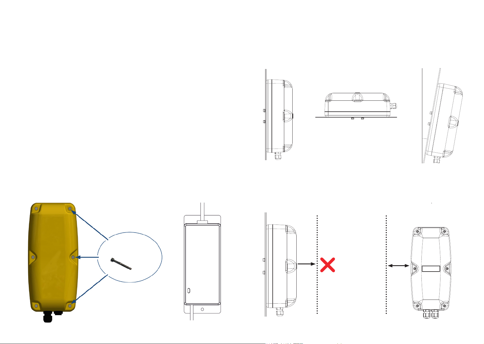
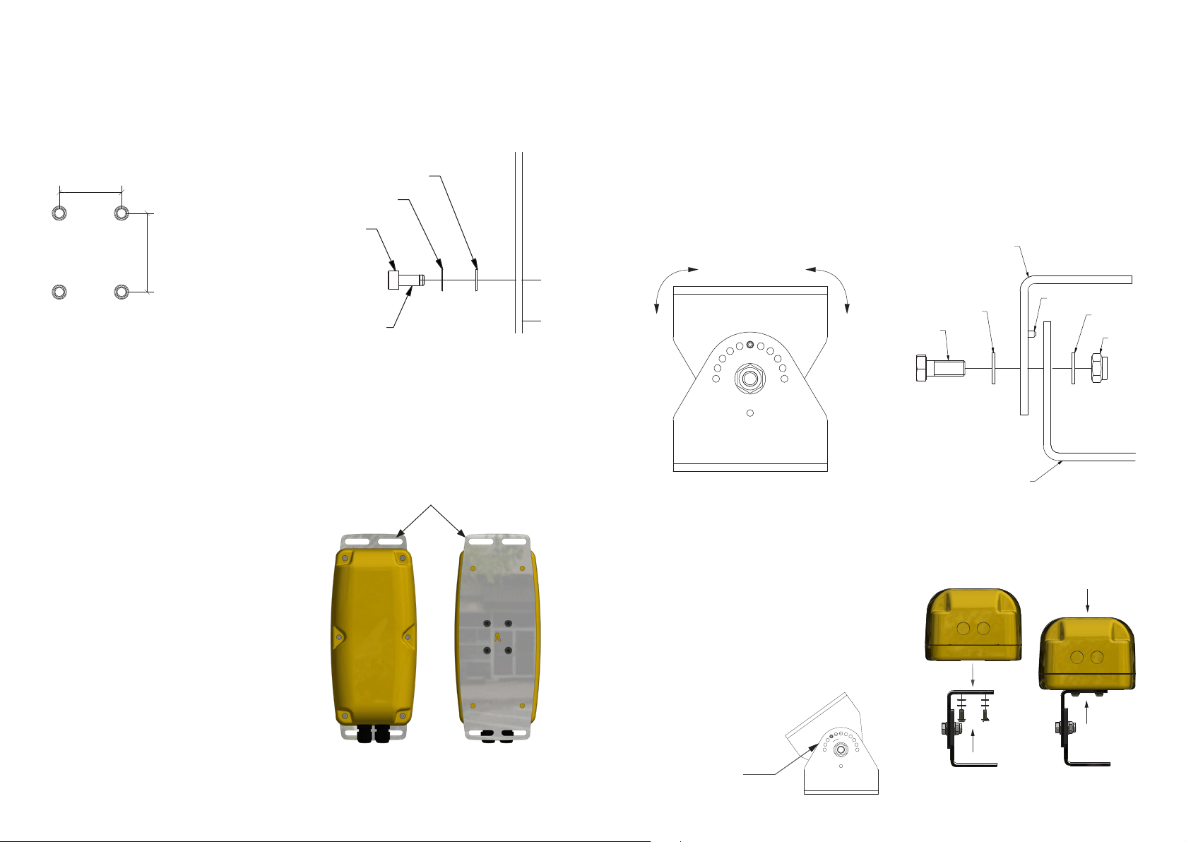
Fixing
4 x M5 screw inserts are located on the rear of the Masking Zone Antenna.
Centres at 30mm by 38mm conform to the industry standard AMPS hole pattern.
Maximum thread engagement into enclosure 8mm.
DETAIL A
SCALE 1 : 1
SECTION B-B
SCALE 2:1
SECTION C-C
SCALE 2:1
VIEW D-D
SCALE 1 :3
A
B B
C C
D
1
123456
A
B
C
D
E
F
REV: DATE: CHANGE:
STATUS:
CUSTOMER:
SCALE @
DRAWN BY:
REV:
DRAWING NO:
TITLE:
UNCONTROLLED
SHEET
A1
THIS DRAW ING IS THE PRO PERTY OF AND M AY EMBODY PRO PRIETARY INFO RMATION
OWNED BY AVONWOOD D EVELOPMENTS LT D. IT IS PROVIDED UNDE R A CONFIDENTIAL
RELATIONSHIP F OR A SPECIFIC PURPOSE . THE RECIPIENT AGRE ES TO USE IT ON LY FOR
SUCH PURPOSE.
AS INDICATED IN ISO 2768-1
TOLERANCE CLASS
LINEAR = f
ANGULAR = f
BROKEN EDGES = f
1 / 1
UNLESS OTHERWISE STATED
3.00
7.40
12.00
1.60
5.40
3.00
1.60
10.00
0.00 200mm
200.00
38mm/
1.5" (11/2")
30mm
/1.18" (13/16")
DETAIL A
SCALE 1 : 1
SECTION B-B
SCALE 2:1
SECTION C-C
SCALE 2:1
VIEW D-D
SCALE 1 :3
A
B B
C C
D
1
123456
A
B
C
D
E
F
REV: DATE: CHANGE:
STATUS:
CUSTOMER:
SCALE @
DRAWN BY:
REV:
DRAWING NO:
TITLE:
UNCONTROLLED
SHEET
A1
THIS DRAWING IS THE PROPERTY OF AND MAY EMBODY PROPRIETARY INFORMATION
OWNED BY AVONWOOD DEVELOPMENTS LTD. IT IS PROVIDED UNDER A CONFIDENTIAL
RELATIONSHIP FOR A SPECIFIC PURPOSE. THE RECIPIENT AGREES TO USE IT ONLY FOR
SUCH PURPOSE.
AS INDICATED IN ISO 2768-1
TOLERANCE CLASS
LINEAR = f
ANGULAR = f
BROKEN EDGES = f
1 / 1
UNLESS OTHERWISE STATED
3.00
7.40
12.00
1.60
5.40
3.00
1.60
10.00
M5 Plain Washer
M5 Int. Tooth Shakeproof Washer
M5 x 0.8mm Pitch
Thread Lock
(optional)
You can use the hole conguration above to attach a 1.5" Ball RAM Mount
base and any conguration of RAM mount xtures. Holes can be made directly
on the vehicle and xing can be done from the back through the vehicle body
and into the xings.Thread lock and shake-proof washers are recommended -
always fasten securely but do not over-tighten.
1.6 Nm Torque MAX
Mounting Plate
Front Back
Adjustable Angle Bracket (supplied seperately)
The Adjustable Angle Bracket is also available for the Masking Zone Antenna
enabling the unit to be installed vertically even when attached to a sloping
frame.
Ensuring the Masking Zone Antenna is installed vertically (see page 3) means
the unit will perform at it’s optimum level.
Mount /
Plate
1
123456
A
B
C
D
E
F
REV: DATE: CHANGE:
STATUS:
CUSTOMER:
SCALE @
DRAWN BY:
REV:
DRAWING NO:
TITLE:
UNCONTROLLED
AVONWOOD INTERNAL
PIVOTLOC
BRACKET SHARED
IMAGES
AS SHOWN
SHEET
N/A
A
A0
THIS DRAW ING IS THE PR OPERTY OF AND M AY EMBODY P ROPRIETARY IN FORMA T
OWNED B Y AVONWOOD DEV ELOPMEN TS LTD. I T IS PROV IDED UND ER A CONFIDEN
RELATION SHIP FOR A SPE CIFIC PUR POSE. THE REC IPIENT AGR EES TO U SE IT ONL Y
SUCH PUR POSE.
MH
AS INDICATED IN ISO 2768-1
TOLERANCE CLASS
LINEAR = f
ANGULAR = f
BROKEN EDGES = f
1 / 1
UNLESS OTHERWISE STATED
EXPLODED VIEW
UNLOCK
ROTATE TO NEW POSITION
LOCK POSITION
BUTTON HEAD M5X12
M5 SHAKEPROOF
M5 PLAIN WASHER
MAX TORQUE 1.6Nm
15.0015.0020.0015.0015.00
10.00
30.00
38.00
5.80
80.00
58.00
HOLE POSITIONS
AND DIMENSIONS
OVERALL DIMENSIONS
80.00
96.00
68.90
02 7125 - Pin Bracket
Bolt
Washer
Lock Pin
Nut
Washer
02 7124 - Plain Bracket
Side View of Adjustable
Angle Bracket
Bracket pivots to keep
Masking Zone Antenna
upright
Exploded View of Adjustable
Angle Bracket
How to Rotate
Adjustable Angle Bracket
The Adjustable Angle Bracket should
be unscrewed rst. Then it can be
adjusted using one of the preset holes
and locked into position by screwing
the bracket together again.
1
123456
A
B
C
D
E
F
REV: DATE: CHANGE:
STATUS:
CUSTOMER:
SCALE @
DRAWN BY:
REV:
DRAWING NO:
TITLE:
UNCONTROLLED
AVONWOOD INTERNAL
PIVOTLOC
BRACKET SHARED
IMAGES
AS SHOWN
SHEET
N/A
A
A0
THIS DRAWING IS THE PR OPERTY OF AND MAY EMBO DY PROPRIETARY INFORM AT
OWNED BY AVO NWOOD DEVELOPMEN TS LTD. IT IS PR OVIDED UNDER A CONF IDEN
RELATIONSHIP FOR A SPECIFICPUR POSE. THE RECIPIE NT AGREES TO USE ITONLY
SUCH PURPOSE.
MH
AS INDICATED IN ISO 2768-1
TOLERANCE CLASS
LINEAR = f
ANGULAR = f
BROKEN EDGES = f
1 / 1
UNLESS OTHERWISE STATED
EXPLODED VIEW
UNLOCK
ROTATE TO NEW POSITION
LOCK POSITION
BUTTON HEAD M5X12
M5 SHAKEPROOF
M5 PLAIN WASHER
MAX TORQUE 1.6Nm
15.0015.0020.0015.0015.00
10.00
30.00
38.00
5.80
80.00
58.00
HOLE POSITIONS
AND DIMENSIONS
OVERALL DIMENSIONS
80.00
96.00
68.90
Adjust angle of
Adjustable Angle
Bracket using one
of the 11 preset
holes and lock
into position
Attaching Adjustable
Angle Bracket To
Masking Zone Antenna
1
123456
A
B
C
D
E
F
REV: DATE: CHANGE:
STATUS:
CUSTOMER:
SCALE @
DRAWN BY:
REV:
DRAWING NO:
TITLE:
UNCONTROLLED
AVONWOOD INTERNAL
PIVOTLOC
BRACKET SHARED
IMAGES
AS SHOWN
SHEET
N/A
A
A0
THIS DRAWING IS THE PROPE RTY OF AND MAY EMBODY PROPR IETARY INFORMAT
OWNED BY AVONW OOD DEVELOPMENT S LTD. IT IS PROVI DED UNDER A CONF IDEN
RELATIONSHIP FOR A SPECI FIC PURPOSE. THE REC IPIENT AGREES TO U SE IT ONLY
SUCH PURPOSE.
MH
AS INDICATED IN ISO 2768-1
TOLERANCE CLASS
LINEAR = f
ANGULAR = f
BROKEN EDGES = f
1 / 1
UNLESS OTHERWISE STATED
EXPLODED VIEW
UNLOCK
ROTATE TO NEW POSITION
LOCK POSITION
BUTTON HEAD M5X12
M5 SHAKEPROOF
M5 PLAIN WASHER
MAX TORQUE 1.6Nm
15.0015.0020.0015.0015.00
10.00
30.00
38.00
5.80
80.00
58.00
HOLE POSITIONS
AND DIMENSIONS
OVERALL DIMENSIONS
80.00
96.00
68.90
1
123456
A
B
C
D
E
F
REV: DATE: CHANGE:
STATUS:
CUSTOMER:
SCALE @
DRAWN BY:
REV:
DRAWING NO:
TITLE:
UNCONTROLLED
AVONWOOD INTERNAL
PIVOTLOC
BRACKET SHARED
IMAGES
AS SHOWN
SHEET
N/A
A
A0
THIS DRAWING IS THE PROPE RTY OF AND MAY EMBODY PROPR IETARY INFORMAT
OWNED BY AVONW OOD DEVELOPMENT S LTD. IT IS PROVI DED UNDER A CONF IDEN
RELATIONSHIP FOR A SPECI FIC PURPOSE. THE REC IPIENT AGREES TO U SE IT ONLY
SUCH PURPOSE.
MH
AS INDICATED IN ISO 2768-1
TOLERANCE CLASS
LINEAR = f
ANGULAR = f
BROKEN EDGES = f
1 / 1
UNLESS OTHERWISE STATED
EXPLODED VIEW
UNLOCK
ROTATE TO NEW POSITION
LOCK POSITION
BUTTON HEA
M5 SHAKEPR
M5 PLAIN W
MAX TORQU
E 1.6Nm
15.0015.0020.0015.0015.00
10.00
30.00
38.00
5.80
80.00
58.00
HOLE POSITIONS
AND DIMENSIONS
OVERALL DIMENSIONS
80.00
96.00
68.90