Brigade MDR-504GW-500 Operating instructions

2
Table of Contents
1Introduction to MDR 500 Series Technology 3
1.1 Product Features 3
1.1.1 Differences between MDR-504xx-500 and
MDR-508xx-1000 3
1.1.2 Common to MDR-504xx-500 and MDR-
508xx-1000 3
2Kit Contents 4
2.1 MDR-504xx-500 and MDR-508xx-1000 Kits 4
2.1.1 MDR-504xx-500 4
2.1.2 MDR-508xx-1000 4
2.1.3 Common for MDR-504xx-500 and MDR-
508xx-1000 4
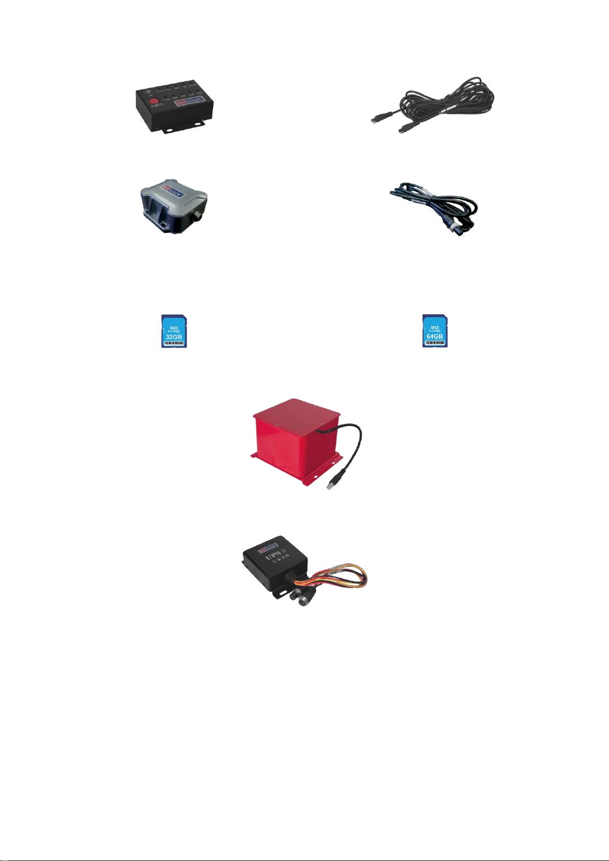
2.2Optional Accessories 5
2.2.1 Remote Status & Interface Panel 5
2.2.2 External G-Sensor 5
2.2.3 SD Cards 5
2.2.4 Fireproof Box with 32GB SD Card 5
2.2.5 Uninterruptable Power Supply 5
3Hardware Installation 6
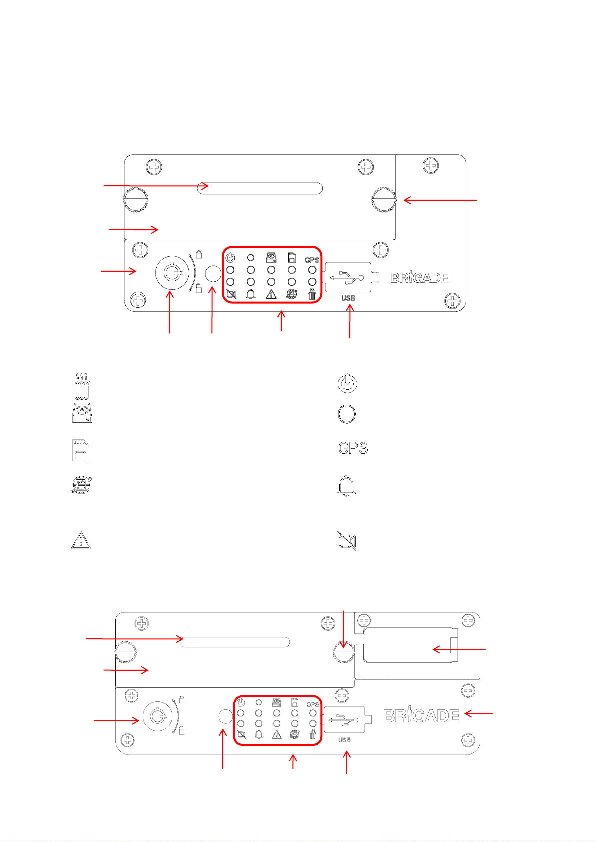
3.1 Front View 6
3.1.1 MDR-504xx-500 Front View 6
3.1.2 MDR-508xx-1000 Front View 6
3.2 Rear View 7
3.2.1 MDR-504xx-500 Rear View 7
3.2.2 MDR-508xx-1000 Rear View 7
3.3 Mobile Caddy Unit (MCU Contains HDD) 7
3.3.1 MDR-500-XXXX MCU 7
3.4 USB Mouse / Remote Control (Optional) 8
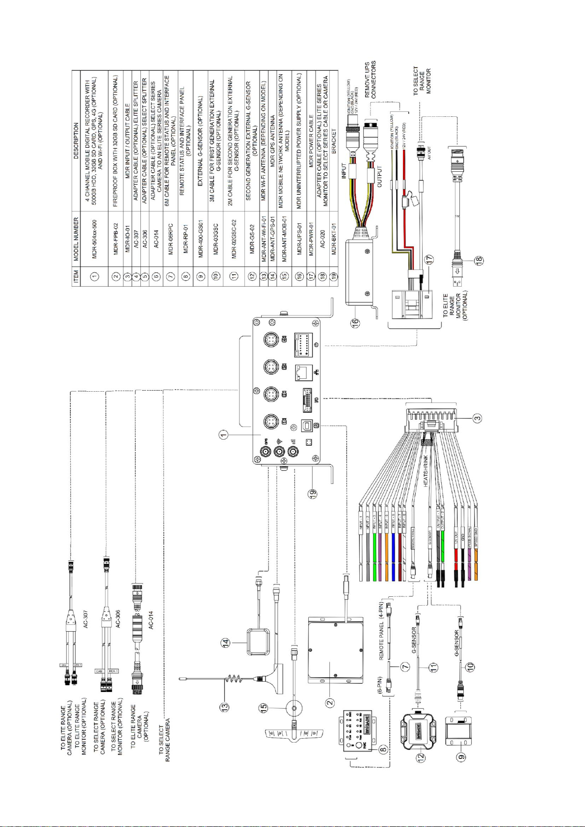
3.5 MDR-504xx-500 Connection Diagram 9
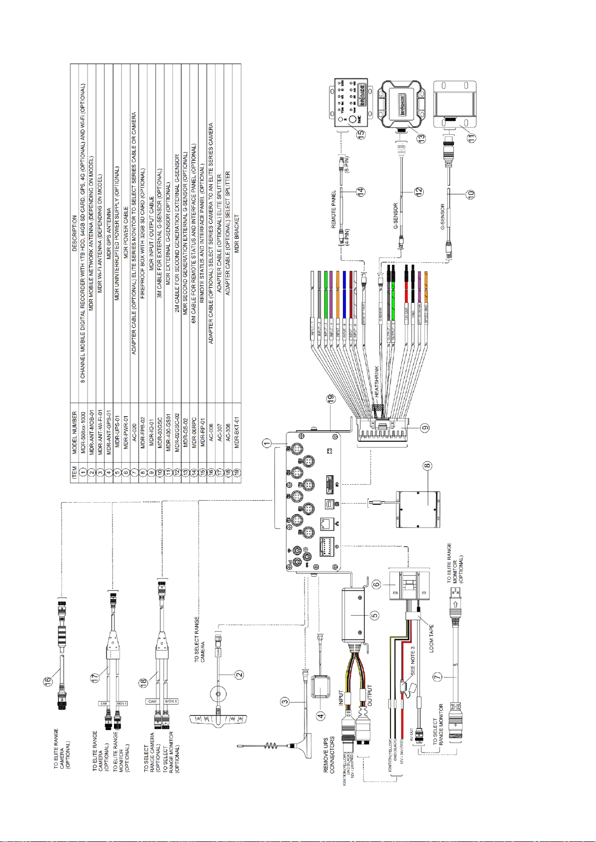
3.6 MDR-508xx-1000 Connection Diagram 10
3.7 Mobile Caddy Unit Removal 11
3.7.1 MDR-504xx-500 MCU Removal 11
3.7.2 MDR-508xx-1000 MCU Removal 11
3.8 SD Card Removal 12
3.8.1 MDR-504xx-500 SD Card Removal 12
3.8.2 MDR-508xx-1000 SD Card Removal 12
3.9 SIM Card Installation 12
3.9.1 MDR-504xx-500 SIM card Installation 12
3.9.2 MDR-508xx-1000 SIM card
Installation/Expansion Module Upgrade 13
3.10 Antennae Installation 13
3.10.1 GPS antenna Installation (Included) 13
3.10.2 Wi-Fi antenna (Depending on Model) 13
3.10.3 Mobile Network antenna (Depending on
Model) 13
4MDR On-Screen Display (OSD) 14
4.1 Quick Menu 14
4.2 Login 15
4.3 Logout 15
5Record Search 16
6Log Search 17
7Setup 18
7.1 Basic Setup 18
7.1.1 Register Information 18
7.1.2 Time Setup 18
7.1.3 Power 19
7.1.4 User Setup 20
7.1.5 Network 20
7.2 Surveillance 22
7.2.1 Live View 22
7.2.2 Record 23
7.2.3 IP Camera Setup 25
7.3 Events 26
7.3.1 General 26
7.3.2 Snapshots 27
7.4 Alarms 28
7.4.1 General 28
7.4.2 Video 29
7.4.3 Advanced 30
7.5 Maintenance 31
7.5.1 Configuration 31
7.5.2 Metadata 32
7.5.3 Upgrade 32
7.5.4 Storage 33
7.5.5 Reset 33
7.5.6 Hardware 34
8System Information 35
8.1 Version Information 35
8.2 Modules 35
8.2.1 Mobile Network 35
8.2.2 Wi-Fi 35
8.2.3 GPS 36
8.3 Server Status 36
8.4 Environment 36
8.5 Storage 36
8.6 History 37
9MDR-Dashboard 5.0 37
9.1 PC System Requirements 37
9.2 Retrieving HDD Data (Quick Guide) 37
9.3 Installing MDR-Dashboard 5.0 38
9.4 Connecting the MCU to the PC 38
9.4.1 Pre-Connection Procedure (Preferred) 38
9.4.2 MCU Connection Procedure (Required)39
9.4.3 Connection Confirmation 39
9.5 Loading from HDD/SD 39
9.6 MDR-Dashboard 5.0 Local Mode 40
9.6.1 Channel Info 41
9.6.2 Events and Graphs 41
9.6.3 Frame Information 42
9.6.4 Sensor Status 43
9.6.5 Map Tracking 43
9.7 Loading from a USB flash drive or Folder 43
9.8 Reading Data 44
9.9 Exporting Videos 45
9.10 Saving Snapshots 46
9.11 User and System settings 46
10 MDR-Player 5.0 48
10.1 Exported MDR-Player 5.0 48
10.2 Setting up MDR-Player 5.0 48
10.3 Basic Operations 48
11 Advanced Ethernet Configurations 51
11.1 Ethernet Setup 51
11.2 Ethernet Operation 52
11.3 Ethernet Maintenance 53
11.4 Ethernet Log 53
11.5 Ethernet Configuration 54
12 On-screen Display Map 54
12.1 Rec Search 54
12.1.1 Rec Search 54
12.2 SYSTEM INFO 55
12.2.1 Version Info 55
12.2.2 Modules 56
12.2.3 Server Status 57
12.2.4 Environment 57
12.2.5 Storage 57
12.2.6 History 57
12.3 LOG SEARCH 58
12.4 SETUP 58
12.4.1 Basic Setup 58
12.4.2 Surveillance 62
12.4.3 Events 66
12.4.4 Alarms 69
12.4.5 Maintenance 76
12.5 LOGOUT ` 78
12.5.1 Logout Prompt 78
13 Mounting Dimensions 78
13.1 MDR-504xx-500 78
13.2 MDR-508xx-1000 79
14 Appendices 79
14.1 Video Quality Table 79
14.2 Normal / Alarm Recording Parameters 79
14.3 Sub-Stream Recording Parameters 80
14.4 User Log Description 80
14.5 Events Table 81
15 Testing and Maintenance 81
15.1 Operator Instructions 81
15.2 Maintenance and Testing 81
16 General Antennae Guidelines 81
17 Troubleshooting 82
17.1 MDR Unit 82
17.2 MDR Fireproof Box 82
18 Specifications 83
19 EU Declaration of Conformity 86
20 Glossary 87
21 Disclaimer 88

3
1 Introduction to MDR 500 Series Technology
Brigade’s MDR-508xx-1000 and MDR-504xx-500 are advanced Mobile Digital Recorders (MDRs) designed to record and playback 8 or 4
channels. The system uses Analog High Definition (AHD), Phase Alternating Line (PAL) or National Television System Committee (NTSC)
television systems. The resolution can be CIF, WCIF, HD1, WHD1, D1, WD1 or AHD. Information related to recording parameters, alarms and
trigger status can be recorded along with speed, location and G-Force data. In addition, data related to the unit itself such as voltage and
temperature are recorded and plotted graphically in MDR Software (MDR-Dashboard 5.0 and MDR-Player 5.0). This information is called
metadata.
Recordings can be searched, viewed and exported (clipped and saved locally) using MDR-Dashboard 5.0 software. This allows users to access
all the vehicle’s travel information, including route tracking. Recordings can be easily exported in three different ways: as a simple audio/video
AVI file playable by consumer media players; as native proprietary format clips or as a password protected .exe file with an embedded MDR-
Player 5.0.
The main storage unit is a large capacity Hard Disk Drive (HDD). The secondary storage is an internal SD (Secure Digital) card for sub-stream,
HDD mirror (simultaneous) or alarm recording. The SD card stores video data and frame information only in chosen image resolution and frame
rate. This is useful in extreme scenarios where the primary storage media reaches its limitations (e.g. a HDD write error during a collision).
Mobile network and Wi-Fi settings found in this manual relate to wireless products as described below. These features can be attained by
upgrading the MDR 500 Series units. 8 channel models allow users to modularly upgrade. These units can be upgraded by various expansion
modules. 4 channel units do not have a modular design to allow for mobile network/Wi-Fi upgrades.
To complete firmware upgrades, configuration imports/exports and video exports a bus-powered hub (minimum 2 ports) is required.
It is imperative that Brigade MDRs are fitted and commissioned by competent and trained technicians. The installers are responsible for the
correct setup of the overall system and must adhere to relevant regulations and legislation.
A brief description of each model is shown below:
•MDR-504GW-500 - MDR 500 Series 4 Channel Mobile Digital Recorder with 500GB HDD, GPS, 4G, Wi-Fi and 32GB SD Card
•MDR-508GW-1000 - MDR 500 Series 8 Channel Mobile Digital Recorder with 1000GB HDD, GPS, 4G, Wi-Fi and 64GB SD Card
•MDR-504-500 - MDR 500 Series 4 Channel Mobile Digital Recorder with 500GB HDD, GPS and 32GB SD Card
•MDR-508-1000 - MDR 500 Series 8 Channel Mobile Digital Recorder with 1000GB HDD, GPS and 64GB SD Card
Warning:Prior to attempting the system setup, please ensure the MDR 500 Series Installation & Operation Guide is thoroughly read
and understood. Brigade will not be responsible for any failures due to incorrect installation or operation.
Ensure your anti-virus software has exclusions in place to allow the MDR software package to function properly.
1.1 Product Features
1.1.1 Differences between MDR-504xx-500 and MDR-508xx-1000
MDR-504xx-500
MDR-508xx-1000
500GB (2TB maximum) 2.5” HDD with anti-vibration mounting
1TB (2TB maximum) 2.5” HDD with anti-vibration mounting
Industrial grade 32GB (256GB maximum) internal SD card for
mirror, sub-stream and alarm recording
Industrial grade 64GB (256GB maximum) internal SD card for
mirror, sub-stream and alarm recording
Simultaneous 4 channel recording up to FULL HD @25fps (PAL) /
@30fps (NTSC) each
Simultaneous 8 channel recording up to HD @25fps (PAL) /
@30fps (NTSC) each or 8 channels at FULL HD @12fps (PAL) /
@15fps (NTSC)
4x Select video connectors typical to camera inputs with audio
8x Select video connectors typical to camera inputs with audio
Weight: 2.2Kg
Weight: 2.75Kg
1.1.2 Common to MDR-504xx-500 and MDR-508xx-1000
•Internal anti-vibration mount for the HDD
•Embedded super-capacitor for finalisation of recording after unexpected power interruption (up to 10 seconds)
•Individual channel configurations for recording resolution, frame rate and quality
•Anti-tampering feature –using digital code
•Display split 1/4/9 channels
•2x EIA/TIA 485 (RS485) for optional External G-Sensor and Remote Status & Interface Panel
•Operation log files for troubleshooting
•Built-in G-Sensor
•Built-in Audible Buzzer
•GPS for location monitoring and tracking with external antenna
•I/O: 8x trigger input (trigger voltage 9V which can be set to trigger at low/high); 2x trigger output (12V max. 200mA)
•USB-B (3.0) interface on the Mobile Caddy Unit (MCU) for displaying video recordings on a Windows™ operating system using MDR-
Dashboard 5.0
•USB-A (2.0) interface on the Docking Station (DS) for downloads, upgrades and configurations onto a USB flash drive (flash memory
only, maximum 16GB)
•Pre-alarm recording 1-60 minutes and Post-alarm recording 0-1800 seconds. (0 to 30 minutes)
•Video quality selectable at 8 different levels for recording
•Video/Audio compression H.264/ADPCM
•Normal, Alarm or Timer recording modes
•Alarm recordings configurable for trigger, speed, G-Force, video loss, motion detection, blind detection, panic button, geo-fencing and
HDD errors
•Low voltage protection with configurable shut-down delay and minimum restart voltage
•Ethernet 10/100 RJ45 port for configuration, live view, playback and video download
•Mouse for configuration and recording/event search
•Shut-down delay configurable from 0 seconds to 24 hours
•12V Output max 1A load
•8.5-36V Power Input
•Operating temperature and humidity: -40˚C to +70˚C and 10% to 90%

4
2 Kit Contents
2.1 MDR-504xx-500 and MDR-508xx-1000 Kits
2.1.1 MDR-504xx-500
MDR 500 Series 4 Channel Control Unit with 500 GB HDD, GPS, 4G, Wi-Fi & 32GB SD Card (Depending on model)
MDR-504xx-500-CU
2.1.2 MDR-508xx-1000
MDR 500 Series 8 Channel Control Unit with 1 TB HDD, GPS, 4G, Wi-Fi & 64GB SD Card (Depending on model)
MDR-508xx-1000-CU
2.1.3 Common for MDR-504xx-500 and MDR-508xx-1000
MDR GPS Antenna
MDR-ANT-GPS-01
MDR Mobile Network Antenna
MDR-ANT-MOB-01
(Depending on model)
MDR Wi-Fi Antenna
MDR-ANT-Wi-Fi-01
(Depending on model)
MDR Input / Output Cable
MDR-IO-01
MDR Power Cable
MDR-PWR-01
MDR USB A to B Cable (USB 3.0)
MDR-USB-B-02
MDR Mouse
MDR-MOUSE-01
MDR Brackets
MDR-BKT-01
MDR Security Key
MDR-KEY-01
MDR Installation CD
MDR-500-CD
MDR 500 Series Installation and
Operation Guide
MDR-500-IG
7x MDR Bracket Fixing Screws
MDR-BKT-FIX-01

5
2.2 Optional Accessories
2.2.1 Remote Status & Interface Panel
MDR Remote Status & Interface Panel
MDR-RP-01-P
MDR 6m Cable for Remote Status & Interface Panel
MDR-06RPC
2.2.2 External G-Sensor
MDR External G-Sensor (Non-IP rated)
MDR-GS-02-G
MDR 2m External G-Sensor Cable
MDR-02GSC-02
Note:
•The internal or external G-sensor needs to be calibrated before use.
2.2.3 SD Cards
32GB Industrial Grade SD Card Class 10
SD-32GB-IND
64GB Industrial Grade SD Card Class 10
SD-64GB-IND
2.2.4 Fireproof Box with 32GB SD Card
MDR Fireproof Box with 32GB SD Card
MDR-FPB-02
2.2.5 Uninterruptable Power Supply
MDR Uninterruptable Power Supply
MDR-UPS-01

6
3 Hardware Installation
Warning
•Connecting any input or output wires to high voltages may damage the product. Brigade will not be responsible for any
damage caused due to negligence.
3.1 Front View
3.1.1 MDR-504xx-500 Front View
MDR-504xx-500 Front View Figure 1
Heater - Yellow LED
ON: HDD Heater is on
OFF: HDD Heater is off
Power –Blue LED
ON: Power on or sleep mode
OFF: Power off
HDD - Blue LED
ON: HDD detected
Flashing: HDD is reading or writing
OFF: HDD is not detected
Recording –Green LED
Flashing: HDD recording
OFF: HDD not recording
SD - Green LED
ON: SD card detected
Flashing: SD card is reading or writing
OFF: SD card is not detected
GPS –Green LED
ON: GPS module is detected
Flashing: GPS module transmitting data
OFF: GPS module is not detected
Network - Green LED
(MDRs with mobile network and/or Wi-Fi functions)
ON: Mobile network / Wi-Fi module detected
Flashing: Centre Server is connected (Data transmission to
the Server)
OFF: Mobile network / Wi-Fi module is not detected
Alarm –Red LED
ON: When an alarm is triggered, lasts for
entire alarm duration
OFF: Alarms not triggered or only events
have been triggered
Error - Yellow LED
ON: HDD/INTERNAL SD not formatted; HDD/INT SD not
installed; HDD/INTERNAL SD been damaged
OFF: MDR working normally
Video Loss –Red LED
ON: When a video loss occurs on an
enabled channel
OFF: All enabled channels have a video
signal
3.1.2 MDR-508xx-1000 Front View
MDR-508xx-1000 Front View Figure 2
Docking
Station
Mobile Caddy
Unit
Infrared
Receiver
Mobile Caddy Unit
Lock and Power Switch
LEDs
USB Port Type A
Thumb screws
to release MCU
Mobile Caddy
Unit Handle
Infrared Receiver
USB Port Type A
Mobile Caddy
Unit
Thumb screws to
release MCU
Mobile
Caddy Unit
Lock and
Power
Switch
SD Card and
SIM Card Slot
Docking
Station
LEDs
Mobile Caddy
Unit Handle

7
3.2 Rear View
3.2.1 MDR-504xx-500 Rear View
MDR-504xx-500 Rear View Figure 3
Rear Panel:
Mobile Network Antenna Connector
Fireproof Box Connector
Wi-Fi Antenna Connector
Ethernet Connector
GPS Antenna Connector
Input / Output Cable Connector
Power Cable Connector
Camera 1 Connector
3.2.2 MDR-508xx-1000 Rear View
MDR-508xx-1000 Rear View Figure 4
3.3 Mobile Caddy Unit (MCU Contains HDD)
3.3.1 MDR-500-XXXX MCU
MDR-500-XXXX-MCU Figure 5
Not Used
4 Channel SELECT
Type Camera
Connectors
Power Cable
Connector
GPS Connector
(Mobile network
and Wi-Fi
depending on
model)
Ethernet Cable
Connector
Input / Output
Cable Connector
Fireproof Box
Connector
Fireproof Box
Connector
Ethernet Port
GPS
Connector
(Mobile
network
and Wi-Fi
depending
on model)
Input / Output
Cable Connector
Power Cable
Connector
8 Channel
SELECT
Type
Camera
Connectors
Not Used
USB-B 3.0 PC Connection
Connector to Docking Station

8
3.4 USB Mouse / Remote Control (Optional)
MDR-MOUSE-01 Figure 6
MDR-RC-01 Figure 7
Note: Remote control buttons that are not described in MDR-RC-01 Figure 7 have no function with the MDR-504xx-500 and MDR-508xx-1000.
Right Mouse Button
Scroll Wheel / Third Mouse Button
Number Keypad
Used for either entering numerical
values or to trigger individual camera
views.
Power –No Function
Button 0is used to either enter
numerical value or to trigger split
views in the following order: CH.1-4;
CH. 5-8 and CH. 1-8
Setup is used for accessing the OSD.
If security is enabled it requires
password.
Navigation buttons are used browsing
the OSD.Left Mouse Button
Record/STOP –No Function

9
3.5 MDR-504xx-500 Connection Diagram
MDR-504xx-500 Connection Diagram Figure 8

10
3.6 MDR-508xx-1000 Connection Diagram
MDR-508xx-1000 Connection Diagram Figure 9

11
3.7 Mobile Caddy Unit Removal
Warning:Follow the removal steps shown below. Failure to do so over a prolonged period may damage the HDD. Ensure that the PWR
LED indicates the MDR is OFF prior to removal.
3.7.1 MDR-504xx-500 MCU Removal
MCU Removal for MDR-504xx-500 Figure 10
3.7.2 MDR-508xx-1000 MCU Removal
MCU Removal for MDR-508xx-1000 Figure 11
Step 3
Completely undo the two
thumb screws (anti-clockwise)
Step 1
Unlock the MCU using the
key
Step 2
Confirm that
the PWR LED
is OFF
Step 3
Completely undo the two thumb
screws (anti-clockwise)
Step 1
Unlock the MCU using the key
Step 2
Confirm that the
PWR LED is OFF
Step 4
Gently pull the MDR-500-1000-MCU by
holding the front handle
Note: If space is limited, the MCU can be
removed in an upright direction
Step 4
Gently pull the MCU by holding the front
handle
Note: If space is limited, the MCU can be
removed in an upright direction

12
3.8 SD Card Removal
Note: To remove an SD card from an MDR, the MCU needs to be removed first (see SD Card removal for MDR-504xx-500 Figure 12 and SD
Card removal for MDR-508xx-1000 Figure 13).
3.8.1 MDR-504xx-500 SD Card Removal
SD Card removal for MDR-504xx-500 Figure 12
3.8.2 MDR-508xx-1000 SD Card Removal
SD Card removal for MDR-508xx-1000 Figure 13
3.9 SIM Card Installation
3.9.1 MDR-504xx-500 SIM card Installation
MDR-504xx-500 SIM card Installation Figure 14
Step 2
Push and depress the SD card to remove the
card from its slot. SD card are inserted with
contacts facing upwards.
Step 1
Gently open the door marked (as indicated
by the arrow on front of MDR-508-EXP) to
reveal the SD card slot.
Step 2
The SD Card is placed in a SD card slot. Remove and
discard the plastic tape covering the SD card.
Push and depress the SD card to remove the card from
its slot.
Step 1
Push the clip away from you while
lifting the lid.
Step 1
Remove the MCU unit. This will allow you to
access the SIM card slot.
Step 2
Use the clip to flip the door open. Ensure an
earthing strap is worn to prevent any damage
to the PCB. Remove the film that is placed
over the SIM card slot. Insert the SIM card
with the contact pins face down. Push the SIM
to lock the SIM securely in place.

13
3.9.2 MDR-508xx-1000 SIM card Installation/Expansion Module Upgrade
MDR-508xx-1000 SIM card Installation Figure 15
3.10 Antennae Installation
The information found in this sub-chapter may be found in the FCS1362:2016 UK CODE OF PRACTICE for the installation of mobile radio
and related ancillary equipment in land based vehicles. Please use this document for further details. Please see Appendix Chapter 16 General
Antennae Guidelines for more information.
3.10.1 GPS antenna Installation (Included)
The GPS antenna needs to have an unimpeded view to the sky. The antenna positioning and orientation is critical to ensure effective
operation. Horizontally mounted on a metal plate is optimum.
3.10.2 Wi-Fi antenna (Depending on Model)
Before a magnetic mount antenna is fitted both the underside of the base and the selected body panel surface should always be cleaned
to avoid damage to the paint work.
➢They must be directly placed on a flat area of steel
➢They should not have any other material inserted between the magnetic base and vehicle body other than a protective pad or boot
supplied by the antenna base manufacturer. This is to avoid reduction in the magnetic retention strength and any effect on the
coupling to the ground plane.
3.10.3 Mobile Network antenna (Depending on Model)
On-glass antennas must be:
➢securely fitted and fixed away from any metal which could deflect the signal
➢located such that driver visibility is not impaired
➢avoid heated screen elements
➢mounted outside of the swept area of the windscreen
Step 1
Remove the MCU and open the expansion
module door to access the SIM card slot.
Insert the SIM card and push the SIM to lock
the SIM securely in place.
Step 2
Ensure an earthing strap is worn to prevent any
damage to the PCB. Undo the screw on the
rear panel (shown above left). Undo the two
screws on the front panel of the expansion
module (shown above right).
Step 3
Open expansion module door. Pull
gently towards you to remove the
expansion module. Insert the new
expansion module by ensuring the
base plate is sliding into the base
grooves of the MDR.
This modular design allows for easy
upgrading or downgrading of 8 channel
MDR units. To upgrade to a mobile
network/Wi-Fi solution, users need to
swop the MDR-508xx-EXP to a model
with these features.

14
4 MDR On-Screen Display (OSD)
This chapter describes the configuration of the MDR.
Brigade’s 500 Series MDR displays a start-up screen. See MDR
Initialisation Screen Figure 16. During this period, the MDR
completes a disk check which helps in identifying any file errors or
bad sectors. In doing so, the MDR will avoid writing to these sectors
to maintain data integrity.
If required, the MDR will attempt to repair any bad sectors prior to
entering its recording state. The MDR 500 Series takes approximately
50 seconds to enter a recording state once ignition has been applied.
Warning:The start-up time to recording for the MDR 500 series is
approximately 50 seconds. Please wait at least 3
minutes after ignition is applied. Brigade will not be
responsible for any events not recorded during this
start-up period. There are three ways in which a user
can tell if the MDR is recording: a visible blue HDD and
a green SD card on each channel; MDR REC LED will
be on; Remote Panel REC LED will be on (optional
accessory).
MDR Initialisation Screen Figure 16
4.1 Quick Menu
Use SAVE which is located at the bottom of each page after
making any changes. Leaving a page prior to saving will cause any
changes to be lost.
To access the quick menu, use the right button on the mouse .
See Quick Menu Figure 17. Clicking this button again will make
any currently displayed OSD disappear. The right button can also
be used as a quick exit button.
By default, the quick menu appears on the bottom of the display
area. Although, if this is blocking any key information, you may
click, hold and drag the quick menu up or down to change its
position. See Quick Menu Position Changed Figure 18.
Quick Menu Figure 17
Three different view options are available in the quick menu:
Single, Quad and 9-Split. See Quick Menu Figure 17, Single View
Figure 19 and 9-Split View Figure 20.
Playback requires login details to access; this will be covered in
Chapter 5 Record Search.
Sys Info
will be covered in Chapter 8 System Information.
Quick Menu Position Changed Figure 18
Single View Figure 19
9-Split View Figure 20

15
4.2 Login
By default, there are two user accounts: admin and user. The
password for the admin account is admin. The password for
the user account is user.
Monitors should scale the MDR video output automatically, but some
monitors do not do this. If your screen is being partially cut-off, the
MDR output margins can be manually adjusted by navigating to
Setup -> Surveillance -> Live View -> Preview -> Margins Setup.
Ensure all white borders are visible. See 7.2.1.1 Preview for further
details.
Note: When accessing the menu, recording continues without any
interruptions.
Once the login is successful, the OSD menu is displayed. See Menu
Structure Figure 23. The menu is navigated using mouse movement
and the left button. See MDR-MOUSE-01 Figure 6 for further
information.
Language will be supported in future MDR firmware versions.
MDR Login Screen Figure 21
Prior to using the MDR please set the MDR to default settings and
clear all history information.
Default settings are achieved by: Setup MaintenanceReset
Factory Settings Restore.
Clear history information by: System Info HistoryClean.
A complete OSD map is found in Chapter 12 On-screen Display
Map.
MDR Default Users Figure 22
Once you have logged in, the menu structure will be displayed as
shown in Menu Structure Figure 23.
This menu consists of: Recordings Search, System Information, Log
Search, Setup and Logout.
There are help buttons found throughout the MDR OSD menu.
These buttons contain additional information to help explain
features, settings and functions.
Menu Structure Figure 23
4.3 Logout
Logout is used to log off a user account that is used to access
the MDR menu. Ensure that you log off once you have finished
your configurations.
Logout Figure 24

16
5 Record Search
Rec Search allows you to search based on source, type, channel, date,
month, year and time.
Source can be selected to retrieve the data. This can be HDD, Sub-
stream SD or Main Stream SD. By default, HDD is selected. HDD
recording represents higher quality recordings found on the HDD. This is
usually set to a better resolution than Sub-stream SD data. Sub-stream
represents a lower resolution recording that is found on the SD card. SD
data types will contain frame information only.
Once you have chosen the date, click Next.
Rec Search Figure 25
Now the search results are shown, see Search Results Figure 26. Video
type options are All, Normal or Alarm. If you are not certain of the type,
choose All.
Channel lets you choose which channel video you would like to view.
Each channel will be displayed in full screen.
Once you click Search the Video results are displayed. See Video
Results Figure 27.
Search Results Figure 26
In this window, you will be able to choose a channel and time. Ticked
channel boxes will load this data during playback.
If you click Playback it will automatically start playing Channel 1 when
the video data starts for that day.
Note: If playback of a video recording is in a different video format from
the current settings (example NTSC or PAL), it cannot be played. Please,
switch the video format. You do this by navigating to Setup -> Surveillance
-> Record -> General -> Video Format.
You can click on the timeline to a desired time or choose the time using
the number pad . You can move the button to your chosen
time, by clicking and dragging while left clicking.
is used to navigate earlier or later in that day.
is used to zoom in and out on the timeline.
Video Results Figure 27
During Playback, the following
functions are available:
Show/Hide Volume menu
Choose time using
number pad
Volume Increase
Volume Decrease
Mute Volume
Next Channel
Previous Channel
Rewind x2 x4 x8 x16
Play / Pause
Fast Forward x2 x4 x8 x16
Slow Forward 1/2 1/4 1/8 1/16
Step
Back
Playback Figure 28
Once you click Export in
Video Results Figure 27, then
Start Time Export Figure 29 is
displayed.
By default, the timeline for one
whole day (24 hours) is
displayed. Enter the start time of
your export, once you are happy
with the time, then click Start
time. See Start Time Export
Figure 29.
Enter the end time of your export
and click End time. See End
Start Time Export Figure 29
End Time Export Figure 30

17
Time Export Figure 30.
The duration and estimated
capacity will be displayed. See
Export Estimate Figure 31.
Once the start and end times
are correct, insert a bus-
powered USB hub into the
MDR front USB. Then connect
your mouse and USB Flash
drive to this hub and click
Export.
An export detail window will be
shown, see Export Details
Figure 33. Choose
Proprietary or AVI.
Proprietary is secure and
contains metadata, it is played
using MDR-Dashboard 5. AVI
is playable on industry media
players such as WMP.
Errors can occur such as no
external storage detected or a
lack of memory space. If this
does, unplug and replug the
USB flash drive or insert a
larger capacity flash drive.
Click Ok. Exporting progress
will be shown in Exporting
Progress Figure 32.
Export Estimate Figure 31
Exporting Progress Figure 32
Export Details Figure 33
6 Log Search
Log Search allows you to search based on type, date, month,
year and time.
Click Next once you have chosen your required date.
In the next window, enter your Start Time and End Time of the
period.
Log Type can be Alarm, Operation and Locked. Alarm logs
contain logs related to Input/output triggers, Panic Button, Speed, G-
Force, Video Loss, Motion Detection, Blind Detection and Geo-
Fence. Alarm logs can be filtered. Operation logs show all logs
related to MDR functions, see Operation Log Figure 36. Locked logs
show logs related to files that are locked by the user. This is
configured by the user.
Log Search Figure 34
Log Details Figure 35
Operation Log Figure 36

18
7 Setup
This chapter describes the setup of the MDR. Settings related to basic setup, surveillance, events, alarms and maintenance. All settings are
contained in the MDR Docking Station (DS). This means that Mobile Caddy Unit (MCU) swapping is easily supported if vehicle registrations are
completed.
7.1 Basic Setup
Use SAVE which is located at the bottom of each page after making any changes.
Warning: Leaving a page prior to saving will cause changes to settings to be lost.
7.1.1 Register Information
7.1.1.1 Vehicle Information
Vehicle Registration is an important field which
should always be populated. The vehicle registration is
stored on the docking station and is then copied onto the
current MCU recordings. This helps in identifying which
vehicle the MCU was in at the time of recording. This is
vital information if a fleet of vehicles swap MCUs.
Vehicle Number is typically used in fleet/bus
applications where a vehicle has an associated fleet
number. This can be captured in this field to assist in
identifying the vehicle.
Vehicle Info Figure 37
7.1.1.2 Driver Information
Driver Number is typically used in fleet/bus
applications where a driver has an associated number.
This can be captured in this field to assist in identifying
the driver in the event of an incident.
Driver Name may be populated which would make it
easier in linking a driver’s name with their number.
Driver Info Figure 38
7.1.2 Time Setup
7.1.2.1 General
Date Format can be set to either
DAY/MONTH/YEAR, YEAR-MONTH-DAY or
MONTH/DAY/YEAR. By default, it is set to
DAY/MONTH/YEAR.
Time Format can be either 24 Hours or 12 Hours.
By default, it is set to 24 Hours.
Time Zone includes worldwide time zone options. By
default, this is set to (GMT) DUBLIN, EDINBURGH,
LONDON.
Default is found on most settings pages. This allows
you to easily restore the factory settings for those
settings
Time Setup Figure 39

19
7.1.2.2 Time Sync
Date/Time can be entered manually here.
GPS should be ticked and the GPS antenna should be
mounted in a vehicle location where signal can be
achieved easily. This is the simplest and more reliable
option.
NTP sync refers to network time protocol that is used
to synchronize time with NTP Server PC time. This
should only be used for mobile network or Wi-Fi MDR
units.
Note: When GPS and NTP sync are enabled
simultaneously, GPS takes highest priority. Only if
GPS fails, NTP sync will be used by the MDR.
Time Sync Figure 40
7.1.2.3 Daylight Saving Time (DST)
Allows users to enter the date and time in which the Daylight-
Saving Time will be activated. In the U.K, it starts on the last
Sunday of March at 1:00 AM and ends on the last Sunday of
October at 2:00 AM. Enter the correct time and date of the country
in which the vehicle will be utilised. Whenever DST is not in use,
turn this option to off.
DST Enable is enabled by default. This setting determines
whether daylight savings time is active.
Start represents the month, date, day and time at which DST
begins. By default, this is set to UK DST. If the time zone has been
changed to another country, other than the UK, then the DST
settings will need to be amended to reflect the selected country.
End represents the month, date, day and time at which DST
finishes.
Daylight Saving Time Figure 41
7.1.3 Power
7.1.3.1 On/Off
On/Off Mode has three different modes: IGNITION, TIMER and IGNITION
OR TIMER.
This option determines the conditions for which the MDR will power up. By
default, it is set to IGNITION, which means that the MDR only turns on when an
ignition signal is applied (yellow wire).
Note: Timer mode must not be used for extended periods of time –this will
damage your vehicle’s battery.
Non-stop allows the MDR to record infinitely. Enabling this will disable
Shutdown Delay.
Warning:Using the MDR for prolonged periods of time without ignition
(vehicle running) can drain the vehicle’s battery. Recommend that the Low
Voltage Protection feature is enabled. See 7.1.3.2 Voltage for details.
Shutdown Delay refers to the period the MDR will remain on and recording
once the ignition has been turned off. The range is 0 to 86399 seconds (24
hours). By default, this is 600 seconds (5 minutes). The shutdown delay period
may show up on the OSD for a period longer than your setting, please see the
note below for an explanation.
Note: MDRs are required to be continuously on for approximately 6 minutes. If
an MDR has not been continuously on for 6 minutes, MDR shutdown
delay will be equal to 6 minutes minus MDR on time plus your current
shutdown delay period.
Timer From becomes active once an On/Off Mode that includes timer is
chosen.
On/Off Figure 42
MDR on for 2 mins
MDR on for 6 mins
MDR Shutdown delay = 4 mins + 5 mins
MDR Shutdown Delay
set to 5 mins
10:00
10:03 Ignition removed
MDR Shuts down
10:12
10:00
10:06 Ignition removed
10:11
MDR Shutdown delay = 0 min + 5 mins
MDR Shuts down

20
7.1.3.2 Voltage
Low Voltage Protection Enable is off by default. This feature is
important to use to protect your vehicle’s battery from damage. Ensure this
feature is activated when using the non-stop shutdown delay feature.
Low Voltage is the voltage level which is a dangerously low value. For
a 24V vehicle, the limits are from 21V to 23.5V. For a 12V vehicle, the
limits are from 8V to11.5V.
Start-up Voltage refers to the minimum voltage the MDR must
receive before powering on. For a 24V vehicle, the limits are 24V to 26V.
For a 12V vehicle, the limits are 12V to 14V.
Observe Time is the amount of time the low voltage value must be
observed for. This is to ignore any sudden dips in voltage that recover.
Shutdown Delay is a countdown which begins once the observe time
has been completed. This countdown is displayed on the MDR OSD. LV
represents low voltage. See Low Voltage Shutdown Delay Figure 44.
Low Volt Upload (scroll down on OSD using ) can only be used if a
wireless or mobile network MDR is used. MDR Server software is a
requirement for this feature. Once the MDR detects a low voltage level, it
will send this data back to the MDR Server where it gets stored. This can
then be reviewed later. Depending on MDR model.
Proposed Low Voltage Protection Settings for lead-acid batteries (Note:
Please check if these are suitable for your vehicle):
12V Vehicles
24V Vehicles
Low Voltage:11.7V
Low Voltage:23.7V
Voltage of Start:12.5V
Voltage of Start:24.5V
Observe Time:15 minutes
Observe Time: 15 minutes
Shut Down Delay:5 minutes
Voltage Figure 43
Low Voltage Shutdown Delay Figure 44
7.1.4 User Setup
Menu Idle Time refers to the period for which the menu
will remain active and logged in. Once this period finishes, the
MDR will automatically log off the user.
Username is the name you use to log onto the MDR. By
default, there are two usernames; admin and user.
User Group represents the level of access to the MDR
OSD. There are only two types; Admin and Normal User.
Admin has access to all settings and features. Normal User
has restricted access: sys info, playback and export logs and
videos.
Add is used to create additional user accounts. A maximum
of three user accounts can exist.
Edit is used to change existing user account details.
To remove any password requirements, save the user account
with a blank password.
User Setup Figure 45
7.1.5 Network
7.1.5.1 Ethernet
There are two modes available for Ethernet adaptor
addressing, DHCP and Static.
DHCP Mode refers to the Ethernet adaptor of the
MDR obtaining an IP address automatically from the
network.
Static IP is used to specify the exact network details
you would like the MDR Ethernet adaptor to use.
IP Address refers to the internet protocol address of
the Ethernet adaptor. This address is used to access the
MDR Ethernet menu via LAN cable. Recommended to
ask your internal IT for information and assistance.
Subnet Mask is used to identify network address of
an IP address. By default, this is 255.255.255.000.
Gateway helps route the network traffic. By default,
this is 192.168.001.254.
Ethernet 1 Figure 46
This manual suits for next models
7
Table of contents
Other Brigade Recording Equipment manuals