Bright33 B33CF17W30BN User manual

INSTALLATION INSTRUCTIONS
Brushed Nickel Finish
Toll Free: 1-800-316-2532
Please follow the following steps for installation.
Please read carefully before installing ceiling fan.
Save these instructions, as you
may need them at a later date.
B33CF17W30BN
BRIGHT33™
CONTEMPORARY 50"
3 BLADE CEILING FAN
www.bright33.com
Thank you for purchasing this
Integrated LED Ceiling Fan!
LED
LED LIGHTING

SAFETY INSTRUCTIONS:
ELECTRICAL REQUIREMENTS:
1
Turn power off before installation, inspection, or removal. Use all necessary precautions while performing
this procedure.
Consult a qualified electrician to ensure correct branch circuit conductor. Min 90ºC supply conductors.
Properly ground electrical enclosure. IT IS IMPERATIVE THAT THE OUTLET BOX BE PROPERLY GROUNDED.
This Integrated LED Ceiling Fan has no lamp/bulb to replace.
DO NOT REVERSE THE HOT AND NEUTRAL CONNECTIONS, OTHERWISE SAFETY WILL BE COMPROMISED.
To reduce the risk of fire or electric shock, do NOT use this fan with any solid-state speed control device.
To reduce the risk of person injury, do NOT insert foreign objects in between rotating fan blades.
After completing installation, check all set screws and make sure they are firmly secured.
The outlet box and ceiling support joist must be securely mounted and capable of safely supporting a
minimum of 50 lbs (23K). Use only UL-listed outlet boxes marked “Acceptable For Fan Support.”
To reduce the risk of personal injury, use only set screws provided with the fan for mounting to the outlet box.
NOTE: Outlet boxes commonly used for supporting lighting fixtures may not be acceptable for fan support,
and may need to be replaced. Consult a qualified electrician if in doubt.
To reduce the risk of personal injury, use only approved hanging brackets and screws supplied with this
ceiling fan when mounting to the outlet box.
GENERAL: All electrical connections must be in
accordance with local and National Electrical Code
(N.E.C.) standards. If you are unfamiliar with proper
electrical wiring connections, contact and obtain
the services of a qualified electrician. Use UL or IEC
approved wire only for input/output connections.
Remove ceiling fan and mounting components from
the box, and make sure that no parts are missing,
by referencing the illustration in the installation
instructions.
Fan must be mounted with a minimum of 7 ft. (2.1M) clearance from the trailing edge of the blades to the floor.
• PHILIPS SCREWDRIVER
• STRAIGHT SLOT SCREWDRIVER
• WIRE CUTTER
• ADJUSTABLE WRENCH
• ELECTRICAL TAPE
• STEP LADDER
TOOLS REQUIRED FOR INSTALLATION:
NOT DIMMING COMPATIBLE: This product is NOT
compatible with dimmers. Ceiling fan performance
could be compromised by wiring ceiling fan with
dimmer. DO NOT USE WITH DIMMER(S)!
Your ceiling fan will require a grounded electrical
supply line of 120 volts AC, 60 Hz, 15 amp circuit.

UNPACKING INSTRUCTIONS:
1. (2X) MOUNTING BRACKET
2. (1X) DOWNROD/BALL ASSEMBLY
3. (1X) CEILING CANOPY
4. (1X) FAN MOTOR ASSEMBLY
5. (1X) LED LIGHT KIT FITTER (LIGHT PLATE)
6. (1X) PLASTIC SHADE
7. (1X SET) BLADE
8. HARDWARE BAG INCLUDING THE FOLLOWING:
a. (2X) WOOD SCREW
a. (2X) FLAT WASHER
a. (2X) HANGING BRACKET SCREW
a. (2X) WOOD TASSEL
a. (1X) HOOK
a. BLADE SCREW (VARIES FROM MODEL TO MODEL)
b. FIBER WASHER (VARIES FROM MODEL TO MODEL)
b. (2X) SPRING WASHER
b. (1X SET) BALANCE KIT
9. (1X) SPARK PLATE
2
Remove contents from box. Ensure that no parts are missing. Reference the illustrations included with this
instruction manual.

1SHUT OFF MAIN ELECTRICAL SUPPLY FROM THE MAIN FUSE BOX/CIRCUIT BREAKER!
2INSTALLING THE MOUNTING BRACKET & HOOK (FIGURES 1 & 2)
THE CEILING FAN MUST BE INSTALLED IN A LOCATION WITH A MINIMUM OF 300MM (11.8 IN)
SPACING FROM THE TIP OF THE BLADE TO THE NEAREST OBJECT OR WALL
Insert the SECURITY HOOK through a hole in the OUTLET BOX that allows access to the ceiling joist,
and screw securely into joist.
3INSTALLING THE MOUNTING BRACKET & HOOK (FIGURES 1 & 2) CONT.
Secure the SPARK PLATE & MOUNTING BRACKET to the METAL OUTLET BOX using the OUTLET
BOX SCREWS and SPRING WASHERS.
4INSTALLING THE MOUNTING BRACKET & HOOK (FIGURES 1 & 2) CONT.
Secure by placing 2 WOOD SCREWS and 2 FLAT WASHERS through the outer slots of the
MOUNTING BRACKET and SPARK PLATE, and then onto the WOOD JOIST.
Leave one of the WOOD SCREWS loose enough to allow the safety cable to be looped around before
final tightening.
PLEASE NOTE: For ease of wiring, feed HOUSE WIRES through SPARK PLATE and MOUNTING
BRACKET
Figure 1
Figure 2
HANGING YOUR FAN:
3
5
INSTALLING THE MOUNTING BRACKET & HOOK (FIGURES 1 & 2) CONT.
USING the 2 LONG SCREWS provided, secure the HANGING BRACKET to the ceiling joist, or
other structure capable of supporting at least 40kgs (88.2lbs). Make sure that at least 30mm
(1-3/16in) of the screw is threaded into the support.
PLEASE NOTE: The BRACKET SCREWS provided are for use with wooden structures only.
For structures other than wood, the appropriate screw type MUST be used.

Figure 3
Figure 4
Figure 5
6DOWNROD/BALL ASSEMBLY (FIGURE 3)
Take the DOWNROD BALL off from the DOWNROD by loosening the GROUND WIRE SCREW, and then
remove the bolt (DOWNROD PIN).
7DOWNROD/BALL ASSEMBLY (FIGURE 3) CONT.
Route the SAFETY CABLE, through the same location as where the WHITE & BLACK WIRES exit the
DOWNROD, and then screw the DOWNROD into the COLLAR COVER located above the motor housing.
8DOWNROD/BALL ASSEMBLY (FIGURE 3) CONT.
Align the holes at the bottom of the DOWNROD with the holes in the top of the COLLAR COVER.
Carefully insert the DOWNROD PIN through the hole to lock, and tighten the SECURITY SCREW.
9DOWNROD/BALL ASSEMBLY (FIGURE 3) CONT.
Thread the CANOPY through the top of the DOWNROD, and replace the DOWNROD BALL back onto the
DOWNROD. Secure the DOWNROD BALL with the GROUND WIRE SCREW.
10 ATTACHING THE FAN BLADES (FIGURES 4 & 5)
PLEASE NOTE: The hole in the foam packaging is designed to assist in holding the pre-assembled fan
into position. Insert the top end of the CANOPY COVER into the hole of the foam packaging so that the
motor faces up during assembly (Figure 5).
ATTACHING THE FAN BLADES (FIGURES 4 & 5) CONT.
Insert the BLADES through the side slot on the motor, and align with the 3 holes.
11
Downrod Ball
4

ATTACHING THE FAN BLADES (FIGURES 4 & 5) CONT.
Secure the BLADES with the 3 BLADE SCREWS, and ensure that the 3 BLADE SCREWS are evenly
tightened. Do not over tighten the screws as this can damage the blades.
Repeat this process for all blades.
12
16 HANGING THE FAN (FIGURE 8)
Lift the fan assembly onto the MOUNTING BRACKET. Ensure that the NOTCH OF BALL JOINT is
positioned on the STOPPER OF MOUNTING BRACKET to prevent fan from rotating when in
operation.
17 HANGING THE FAN (FIGURE 8) CONT.
Loop the SAFETY CABLE over the HOOK.
15 INSTALLING THE LIGHT KIT (FIGURES 6 & 7) CONT.
Align the keyholes of the LIGHT PLATE to the screws of the SWITCH HOUSING. Attach the
LIGHT PLATE to the SWITCH HOUSING by securing with the 2 screws loosened in (STEP 13).
Replace the other 2 screws removed from (STEP 13), and secure the LIGHT PLATE by firmly
tightening each screw.
INSTALLING THE LIGHT KIT (FIGURES 6 & 7) CONT.
Connect the light kit lead wires to the fan motor wires: BLACK to BLACK and WHITE to
WHITE. (Fig. 6)
Insert the pull chains through the side holes of the LIGHT PLATE.
14
INSTALLING THE LIGHT KIT (FIGURES 6 & 7)
There are 4 screws on the SWITCH HOUSING as shown (Fig. 7). 2 screws are for the keyholes
of the LIGHT KIT PLATE. Loosen, but do not remove, these 2 screws. Then remove the other
2 screws.
13
Figure 6
Figure 7
Figure 8
5
Slot
Switch housing
White Wire
White Wire
Black Wire
Black Wire
Hole
LED Light plate

Figure 9
18 Make the following wire connections (Fig. 9), using the provided WIRE NUTS:
WHITE (-) SUPPLY WIRE TO WHITE FIXTURE WIRE
BLACK (+) SUPPLY WIRE TO BLACK FIXTURE WIRE & BLUE FIXTURE WIRE
SUPPLY GROUND WIRE TO GREEN GROUND WIRE
If necessary, wrap all wire connections in electrical tape to ensure a secure connection.
20 Carefully tuck all wiring back into the OUTLET BOX. Make sure wires are clear of the hemisphere and
downrod when positioned on the MOUNTING BRACKET.
WIRING:
WALL CONTROL INSTALLATION:
6
Follow this wiring diagram. Wall control sold separately, choose ON/OFF light control only.
ELECTRICAL CONNECTIONS (FOR OPTIONAL WALL CONTROL)

Figure 10
Figure 11
20 After completing the electrical connection, cover the MOUNTING BRACKET with the CANOPY. Ensure that
all electrical wiring is carefully tucked inside the canopy.
21 Secure the CANOPY to the HANGER BRACKET using the SCREWS provided. (Fig. 10)
Remote control sold separately, choose ON/OFF light control only.
GENERAL INFORMATION (FOR OPTIONAL REMOTE CONTROL)
22 Carefully install the PLASTIC SHADE into the light fitter and twist clockwise to lock in place. (Fig. 11)
DO NOT over tighten when installing the PLASTIC SHADE into the LIGHT KIT.
23 Restore power at fuse box/circuit breaker. Check operation of Integrated LED Ceiling Fan.
24 Installation complete.
7

TROUBLE SHOOTING:
• Check that line voltage at fixture is correct.
• Ensure that there is voltage at lamp fixture wires. If there is no voltage, then check all connections.
• Check that fixture is grounded properly.
If fixture does not light/start:
• Check switch to ensure that there are no defects.
• Check fuse/circuit breaker for trips, then check wiring connections.
If fixture sounds noisy:
• Ensure all motor housing screws are fully tightened.
• Ensure that the screws on the fan blade bracket are fully tightened.
• Check that the wire nut connections are not rubbing against each
other, or inside the switch housing wall.
• Allow a 24 hour break period to eliminate most noises.
A slide REVERSE SWITCH is located on the COLLAR COVER, which controls the direction of blade rotation.
The UP position sets the blades in REVERSE rotation. The DOWN position sets the blades in FORWARD rotation.
SUMMER Mode: The REVERSE SWITCH should be in the DOWN (SUMMER) position to make the fan rotate
counter-clockwise. The airflow will be directed downwards for cooling in the summer.
WINTER Mode: The REVERSE SWITCH should be in the UP (WINTER) position to make the fan rotate clockwise.
The airflow will be directed upwards to assist in circulating warm air, in order to conserve energy in the winter.
CAUTION: Wait for the fan to stop before changing the setting of the REVERSE SLIDE SWITCH
OPERATION INSTRUCTIONS:
Connect the WOOD TASSELS to the two pull chains located in the LIGHT KIT. One is for the FAN, and the other is for the LIGHT.
Turn on power and check the operation of your fan.
3-SPEED PULL CHAIN: 1st Pull = High Speed, 2nd pull = Medium Speed, 3rd pull = Low Speed, 4th pull = OFF
To turn the LIGHT KIT “ON” or “OFF”, pull the chain attached to the LIGHT KIT.
CAUTION: Even if the fan is mounted with a minimum of 7 ft. clearance from the trailing edge of the blades to the floor, use
caution and avoid raising your arms or any other object in the paths of the blade.
REVERSE SWITCH OPERATING INSTRUCTIONS (FIGURE 12):
Figure 12
8
If fixture wobbles:
• Check that all blade screws are secure.
• Fan wobble usually occurs when blade
levels are unequal. To check levels, select a
point on the ceiling above the tip of one of
the blades, and check that the downrod
hemisphere notch is engaged in canopy.
• Moisture during transportation may cause
slight weight variations. Use balance kits to
eliminate this problem.

5-YEAR LIMITED WARRANTY:
CAUTION: Ensure fixture temperature is cool enough to touch. DO NOT clean or perform maintenance while fixture
is energized.
• Clean lens and fixture housing with non-abrasive cleaning solution.
• Do not open fixture to clean LED. Do not touch the LED.
• Do not spray liquid directly on to LED, LED driver or wiring.
• Clean fan blades with DRY cloth/duster; moisture may cause blades to warp.
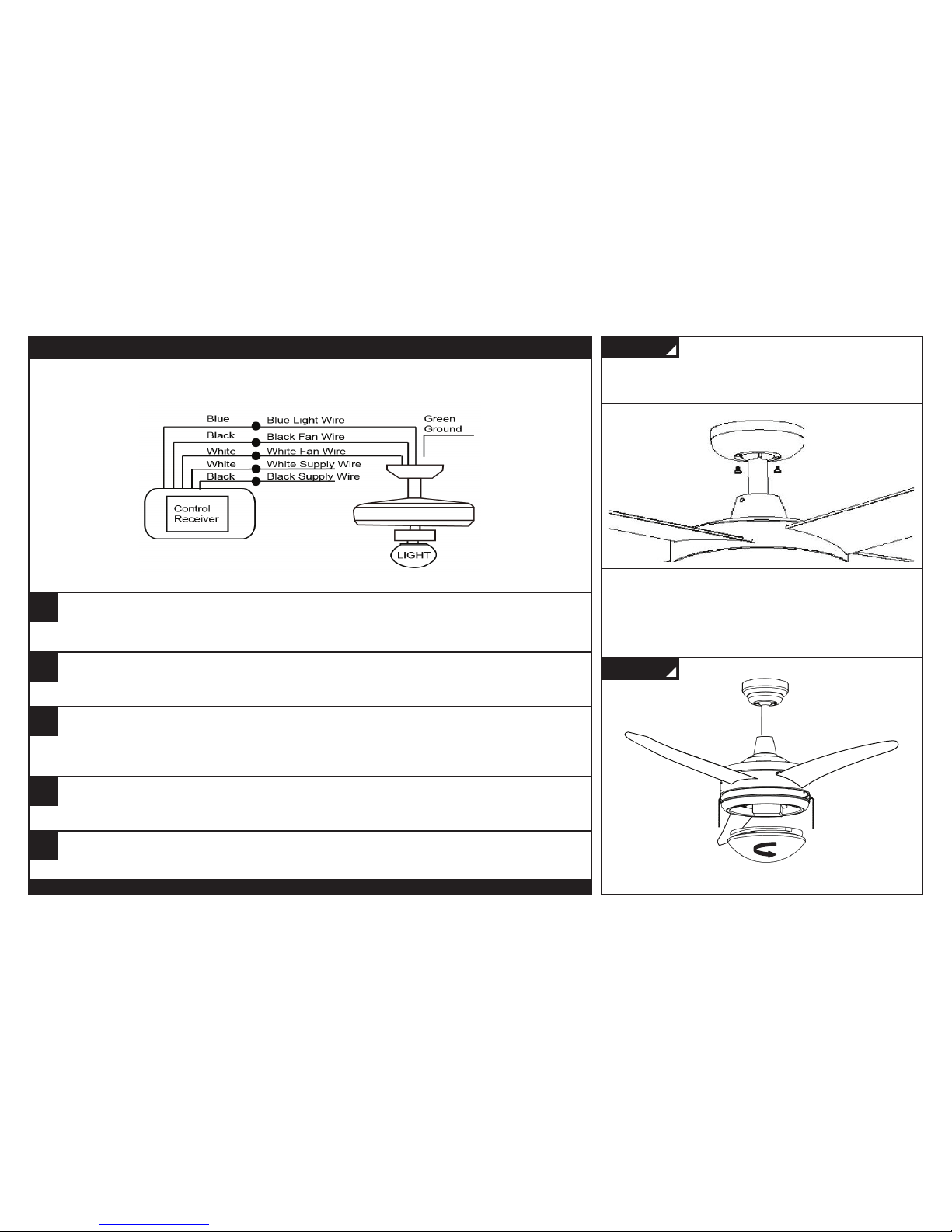
• If fan starts to wobble, make sure blades and fan are tight and rebalance blades if needed. It is normal to rebalance
fan blades—after several years of use, fan may begin to wobble.
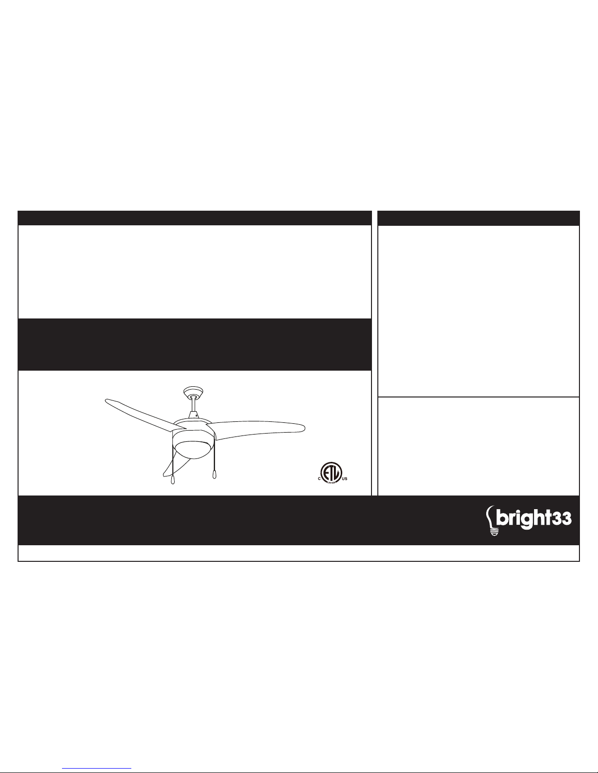
B33CF17W30BN
Thank you for purchasing this
Integrated LED Ceiling Fan!
This device complies with Part 15 of the FCC Rules and has been
tested and found to comply with the limits for Class B digital
device. Operation is subject to the following two conditions: (1) this
device may cause harmful interference, and (2) this device must
accept any interference received, including interference that may
cause undesired operation. Any changes or modifications not
expressly approved by manufacturer could void user’s authority to
operate the equipment.
Please save these instructions, as you
may need them at a later date.
LIMITED WARRANTY: Bright33™ Ceiling Fans are warranted to
be free and clear of defects in materials and workmanship for a
period of five years from the date of purchase based on three
hours of average usage per day for seven days a week. This
warranty covers defects in manufacturing discovered while using
the product as recommended by the manufacturer and does not
apply to failures caused by acts of God or as a result of any
abuse, misuse, abnormal use, or use in violation of any applicable
standard, code, or instructions for use in installations.
If a Ceiling Fan fails due to a defect covered by this warranty,
Stream33 Products LLC will replace the product. To make a
warranty claim, retain the failed products and send with proof of
purchase, register receipt, your name and address to the address
below within thirty (30) days of the failure.
© 2016 Stream33 Products LLC. All rights reserved.
Bright33 is a subsidiary of
Stream33 Products LLC
350 Courtney Road
Sebring, Ohio 44672 USA
LED LIGHTING
CLEANING & MAINTENANCE:
Table of contents
Popular Fan manuals by other brands

iLiving
iLiving ILG8F20 owner's manual

Helios
Helios easyControls 3.0 KWL 200 W Installation and operating instructions

Kichler Lighting
Kichler Lighting Meredith instruction manual

Champion
Champion CHGF115 user manual

Home Decorators Collection
Home Decorators Collection KITTERIDGE 35442-HBUM Use and care guide

Bard
Bard CRVS-3A installation instructions

Breeze
Breeze CPD 160 user manual

Revel AIR
Revel AIR ALBANY Series instruction manual

NuAire
NuAire IAQ-PURGE Installation and Maintenance

NuTone
NuTone Heat-A-Ventlite QT-9093 Series installation instructions

Panasonic
Panasonic FV-08VS1 installation instructions

Progress Lighting
Progress Lighting AirPro P250026 installation manual