Brilix ALBIXON SAL 16 User manual

VERZE 15/09/2022 / REVIZE: 05/01/2023
EN
INSTALLATION
AND USER GUIDE
Control and dosage
equipment
STATION
Portable color
display (TFT)
Upgrade
possible
Worldwide
remote
control
Controls
filtration,
lighting
WIFI and
MODBUS

2/ Hydrolysis - electrolysis low intensity OXILIFE
3
1
2
4
6
5
7
8
10
11
12
13
9
1.
Description
2.
System installation
Item Product description
1. RCA flow detector
2. Fuse for device 3,15 A
3. Fuse for device 250 mA
Electronic box
Item Product description
1. Filtration pump timer *
2. Silex / glass / diatom filter
3. Recirculation pump
4. Electronic box
5. Conductivity probe (optional - for models with conductivity control)
6. pH probe (for models with pH control)
7. redoX probe (for models with redoX control)
8. Free chlorine control
9. Dosing pumps for pool chemicals
10. Acid injector (optional - for models with pH control)
11. Container with pool chemicals
12. Other pool equipment - not supplied with unit
13. Module RF or RF/WIFI or WIFI - not supplied with unit
14. Container with pH minus
15. Dosing pump for pH regulation
Station is a complete pool controller which doses pool-chemicals
in order to maintain the pool water in perfect conditions. The base
product controls the temperature, filtration periods, pool lighting
and 4 additional relays. The base product is upgraded by adding the
measurement and control of up to 4 water parameters.
Electrical consumption
It’s recommended to use a time delay circuit
breaker of 25 A for domestic devices and a time
delay circuit breaker of 40 A for industrial devices.
In case of sharing the power supply with other
devices please consult a technician in order to
dimension a correct installation.
* Filtration control by external timer
* Filtration control by internal timer
Relay FILTER PUMP 110-230 V
Filtration mode:
See section 5 -
Filtration of the
General Installation
Guide
Filtration mode:
“Manual/ON”
1
2
3
Product
Max. consumption
UV 16 230W
15
14

Hydrolysis - electrolysis low intensity OXILIFE / 3
Maintenance 3.
First days of maintenance
During the first 10-15 days your pool system will require more attention and the following care:
1 Make sure the pH remains on the ideal level (6,8–7,2). If the pH is unusually unstable and uses a lot of acid check the alkalinity (recommended levels
between 80 y 125 ppm).
2 The pool must be vacuumed and the skimmers cleaned whenever necessary to ensure perfect water conditions.
General maintenance
1 DOSING PUMPS: Check regularly to ensure that the container contains liquid to prevent the dosing pump of running dry.
2 pH PROBES / redoX / CONDUCTIVITY: Probes must be cleaned whenever necessary (check every 5-6 months). To clean the probe insert in
distilled water (clear liquid). After each cleaning the probes must be calibrated. Also: the probes must be kept wet (if stored). During storage, it is
necessary to keep the probes in proper KCl solution for their regeneration.
Fortnightly checks Monthly checks
Free chlorine: 0,3–1,5 ppm
pH: 6,8–7,2
Total alkalinity (tac) pH: 80–120 ppm
Cyanuric acid: 30–50 ppm
Troubleshooting 4.
WARNING
Keep chemical levels in pool as instructed in this manual.
Work with chemicals very carefully. CHEMICALS MUST NOT BE MIXED UNDER ANY CIRCUMSTANCE!!
EARTHING
All metallic components in the pool such as lamps, ladders, heat exchangers, drains or similar elements within 3 m from the pool (10 feet) must be connected to
an earth below 37 Ohms. If using heat exchangers, we recommend them to be made of titanium.
SECURITY
To avoid accidents, children should not handle this product unless supervised by an adult.
Children should be supervised at all times when in or near a spa, pool or jacuzzi.
Blank display
•
Check if ON/OFF switch is illuminated.
•
Check the connection wire between
display and motherboard.
•
Check fuse of the device 3.15 A – it could
have tripped due to overload.
•
Check the power supply
110V/60Hz – 230V/50Hz.
•
If problem persists contact TECHNICAL
SERVICE
Alarm AL3 and pH dosing pump stopped
•
The maximum dosing time (standard 200 min.) is accomplished and the acid
dosing pump stops in order to avoid the acidification of the water.
•
To delete the message and to restart the metering press
ESC (
). Do the following verifications in order to preclude errors
on the device: Verify if the pH probe reading is correct (if not,
calibrate the probe or substitute it with a new one); Verify if the acid/
base deposit is full and if the dosing pump is working correctly; Verify
the variable speed of the dosing pump.
White flakes in the
water
•
The water is excessively hard
and it is unbalanced.
•
Balance the water and check
the cell, proceeding to clean it
if necessary.
•
Put 1 small bag of flocculant
in the skimmer and recirculate
24 hours.

4/ Hydrolysis - electrolysis low intensity OXILIFE
5.
Electronic box
TOTAL
POOL
CONTROL
TOTAL
POOL
CONTROL
TOTAL
POOL
CONTROL °C pH rH CI2
+4
Filtration
pump control
Complete
pool control
Light control Control of 4
additional
machines
Temperature
control
PH-
management
REDOX-
management
Free chlorine
management
6.
Automatic controls
Description pH Redox Free chlorine Conductivity Temperature
Measuring range 0-12 pH 0-1000 mV 0-10 ppm 0-20,000 MS 0-100°C
Measuring precision 0,1 pH 1-3 mV 0,10 ppm 10 MS / 100 MS 1°C
Material Ag/Cl gel Gold disc Copper / gold Stainless steel
Probe holder ABS 50/63 mm Transparent
methacrylate ABS 50/63 mm
Supplementary equipment Includes 2 m of
flexible tube/valve
Cable 2 m coax 2 m
Plug BNC with protection BNC with protection Inductive sensor
connectors / BNC Connectors Connectors
Description SAL 16
Max. production Cl2/h -
Salt concentration -
Display 2,8’’ TFT mobile (20 m) color display (5 languages)
Power supply 110–230 V 50/60 Hz
Outlet -
Maximum consumption 40 W
Dimensions 270 x 220 x 115 mm
Electronic box Fireproof plastic ABS black
Front cover Plastic ABS orange
Electronic Microprocessor 32 bit
Ventilation -
Working hours recording Yes – accessible by client
Alarms
pH dosing / pH max. dosing time / memory error
Communication MODBUS / WIFI
110–230 V output control (3 outputs) Acid pump / Relay AUX 1 / Relay AUX 2
Potential-free output control (4 outputs) Filtration / Lighting / Heating (AUX 4) / Relay AUX 3
Inlets 2 analogue and configurable inlet signals

Hydrolysis - electrolysis low intensity OXILIFE / 5
Dimensions 7.

6/ Hydrolysis - electrolysis low intensity OXILIFE
8.
Control unit wiring diagram
Water treatment system for swimming pools.
This installation and user manual is a general guide for all Salt water treatment models supplied by spol.
Albixon a.s. Some of the features and settings listed in this guide are valid only for applicable models that
support these features or for optional equipment that is not included in the basic package.
12:30 25º
man
off
man
off
CoverPol 1
LOW
00 gr/h
%
hydrolysis /electrolysis
Pr onPol 1
Pol 2
250 mA
pH7.5 OFF
AL37.0
7.2
Rx
mV
700 OFF
AL3FL1
700
Cl
ppm
1.00 FL2
FL1
1.00
Cu/Agionization
measures
1 2 3 4
TANK
*In case of connecting
2display´s on the device,
remember not to connect
the remote display in this
communication channel. Use
the “EXTERN” channel instead.
DRY CONTACT
110-230 V
max. 3.15 A
pHredoX
pH
pH Control
1& 2
AUX 4
Heating control
15 & 16
AUX 3
13 & 14
LIGHT
Lighting control
11 & 12
AUX 2
redoX / free chlorine
ppm’s (pump) 5& 6
AUX 1
Base (pump) or
Ultraviolet 3& 4
(according to model)
Variable speed pump
1slow 2medium
3fast 4common
Connection WIFI module
1red 2yellow
3green 4black
Free Chlorine
3red 4black
Device control SLAVE
1brown 2blue
FILTER PUMP
Filtration control
9& 10
Chlorine probe
detector FL2
(rotameter)
Cover 1& 5
Conductivity probe
Flow switch
FL1
2& 5
Acid deposit
level
TANK
4& 5
Temperature probe
3black
5brown
6blue
1red
2yellow
3black
1yellow
2transparent
Ionization
7& 8
(according to model)
CONNECTALL THE SENSORS CAREFULLY, A
BAD CONNECTION MAY CAUSE IRREPARABLE
DAMAGE TO THE DEVICE
Ground
Ground
Connection remote display*
1red 2yellow
3green 4black

Hydrolysis - electrolysis low intensity OXILIFE / 7
Main screen 9.
Button display
Touch display
Time
Relay status
To reset the AL3
alarm keep pressed
the pH circle for 3
seconds
FIltration status
Water temperature
Chlorine
production, press
the circle to enter
in the electrolysis
menu
Water readings,
press the circle
to enter in the set
points menu
Lighting status
Main menu access
12:30 25º
man
off
man
off
CoverPol 1
LOW
00 gr/h
%
hydrolysis /electrolysis
Pr onPol 1
Pol 2
250 mA
pH7.5 OFF
AL37.0
7.2
Rx
mV
700 OFF
AL3FL1
700
Cl
ppm
1.00 FL2
FL1
1.00
Cu/Agionization
measures
1 2 3 4
TANK
Current time
Hydrolysis / Electrolysis
Production intensity in % (hydrolysis)
and gr/h (electrolysis)
Cu/Ag Ionization (according to model)
Intensity en mA
Heating ON/OFF
man Manual
aut Automatic
hea Heating
smt Smart
int Intelligent
bst Boost
State filtration relay
(see section 5- Filtration)
Automatic measurements: pH/redoX/
free chlorine/conductivity
(according to options)
Status of the auxiliar relays
Water temperature
Polarity 1 / Pol 2 Polarity 2
Filtration stopped due to lack of water fl w
Waiting time
Cover
Pol 1
Flow
Low
---
Production automatically reduced to
the % selected (see display 3.6)
Lack of conductivity or salt / low water temperature /
scale on cell / exhausted cell (check working hours)
Pr on
Polarity 1 / Pol 2 Polarity 2
Pol 1
Ionizer timer
7.5
7.0
ON/OFF/WT
Setpoint pH maximum (acid control)
ON/OFF: Function of acid pump or base pump
WAIT: Waiting time of acid pump or base pump
AL3
Maximum dosing time exceeded ( to reset the alarm)
Setpoint pH minimum (base control
700
FL 1
ON/OFF
Function of chlorine pump
Flow alarm
Setpoint redoX minimum
Maximum dosing time exceeded ( to reset the alarm)
AL3
AL3
FL 1
1.00
Setpoint Free Chlorine minimum
Flow alarm /
Fl 2
Error rotameter Cl2
Maximum dosing time exceeded ( to reset the alarm)
TANK Low level chemical tank
Ultraviolet ON/OFF (according to model)
Communication display – mother board
red indicates communication error
State relay lighting
man Manual / aut Automatic
PLUS key
Modify value/selection
MINUS key
Modify value/selection
OK key
Select/confir
UP key
Navigation up
DOWN key
Navigation down
RETURN/ESCAPE key

8/ Hydrolysis - electrolysis low intensity OXILIFE
3.1 Hydrolysis/Electrolysis:
Programming of hydrolysis
or electrolysis functions
(according to model).
3.2 Level: Electrolysis -
Desired production of
chlorine (gr/h). Hydrolysis
- Desired disinfection
production (%).
3.6 Cover: connection
of automatic cover. See
section 10-Cover.
3.4 Boost: Filtration during
24h at max intensity.
Automatic return to
programmed filtration
mode. During the boost
period the redoX control
can be deactivated.
3.5 Mode: If the device
has Free Chlorine and
redoX probes, choose the
parameter that controls the
cell’s chlorine generation.
3.3 Salinity:
Measuring gr/l of salt
in water. See section
9-Salinity.
3.1 3.2
3.4
3.3
3.5
3.6
4.1 Measures: Adjustment of setpoints and measuring probes.
4.2 Setpoints for each measurement.
4.3 Setpoints settings: Ideal setpoints for each of the parameters.
The default values are:
pH: 7.3-7.5; redoX: 600-800; Free Chlorine: 0.5-2 ppm;
Conductivity: 1500-2500 for Hydrolysis and 7000-10000 for
Electrolysis.
4.2
4.3
4.1
Setpoints
4.6
pH Calibration
4.5
4.4
4.8
4.7
4.4
Calibration of pH probe: Recommended every
month during usage season.
4.5
Calibration with buers (buer solutions pH7 /
pH10 / neutral): Follow the instructions in 7 steps
that appear in the display (screen
4.6
corresponds
to step 1).
The option Reset Cal clears the calibrations made
previously.
4.7
Manual calibration: Allows to adjust the
probes at 1 point (without buers) – only
recommended to adjust small deviation in the
readings.
4.8
Without removing the probe from the
water, use the plus/minus keys to adjust the
reading so it matches with your reference value
(photometer or other measurement).
Optional pH control
Metering and control of
the pH of the water
redoX Calibration
The redoX value advises us of the oxidation/reduction potential and is used to determine the level of water sterilization. The parameters or setpoints are
the minimum/maximum accepted redoX levels before the titanium cell is connected/disconnected. Adjusting the ideal redoX level (setpoint) is the last
step in the system start up sequence. To find the optimum redoX levels for your pool foll w these steps:
1. Connect the pool filtration system (the salt in the pool must be adequately dissolved).
2. Add chlorine to the pool till a level of 1-1,5 ppm is achieved (approx. 1-1,5 gr/m3of water). pH levels should be between 7,2–7,5.
3. After 30 min. test the free chlorine levels in the pool (manual test kit DPD1) if the free chlorine level is between 0,8–1,0 ppm. Look at the redoX
screen and memorize this level as the setpoint to CONNECT/DISCONNECT the electrolysis/hydrolysis cell.
4. The next day check free chlorine levels (manual test kit DPD1) and redoX. Raise/lower setpoint if necessary.
5. Remember to check the redoX set-point every 2-3 month and/or if the water parameters change (pH/temperature/conductivity).
pH
Hydrolysis / electrolysis
(according to model)
10.
Measures
11.

Hydrolysis - electrolysis low intensity OXILIFE / 9
4.11
4.10
4.9
4.13
4.12
4.9
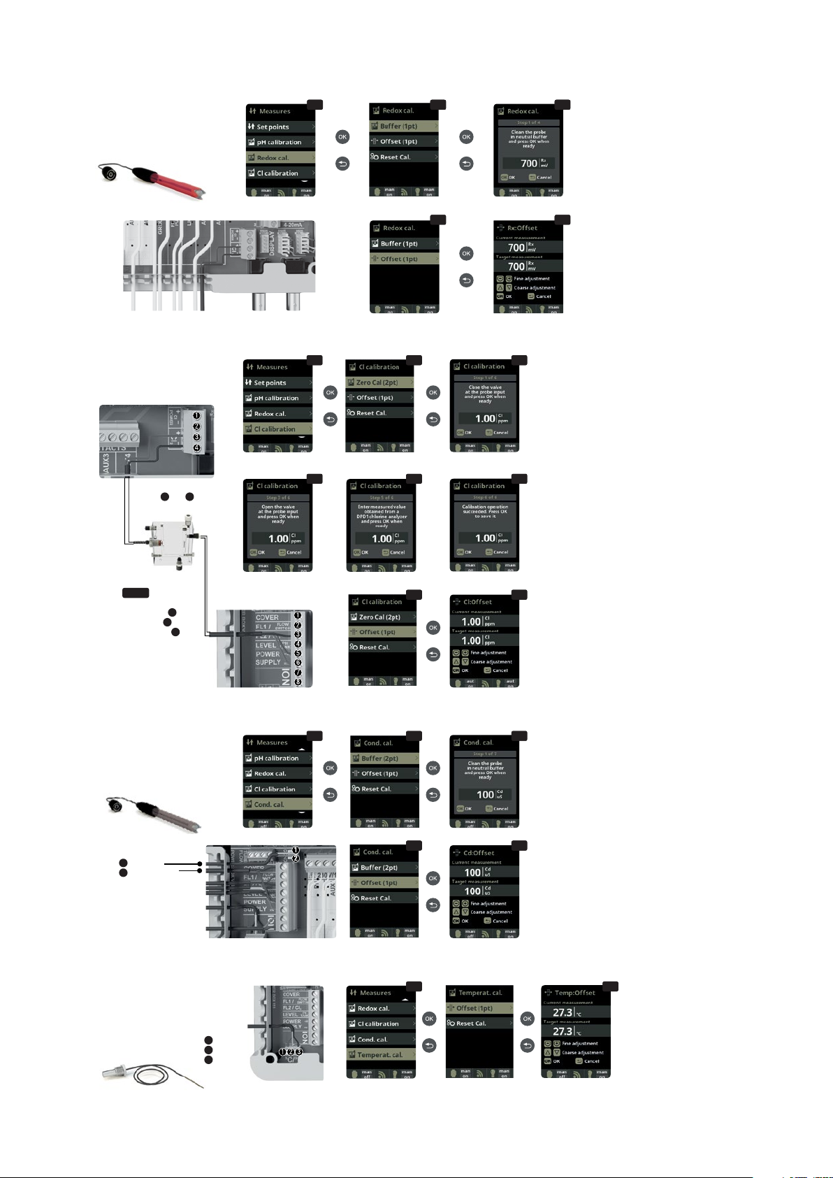
Calibration of the redoX probe: Recommended
every 2 months during usage season.
4.10
Calibration with buer (buer solution
465mV): Follow the instructions in 4 steps that
appear in the display (screen
4.11
corresponds
to step 1).
The option Reset Cal clears the calibrations made
previously.
4.12
Manual calibration: Allows to adjust
the probes at 1 point (without buers) – only
recommended to adjust small deviation in the
readings.
4.13
Without removing the probe from the
water, use the plus/minus keys to adjust the
reading so it matches with your reference value
(photometer or other measurement).
Optional redoX control
Metering and control of the
redoX as check value of the free
chlorine.
redoX
4.14
4.15
Free Chlorine calibration
4.16
4.17
4.18
4.19
4.20
4.21
4.14
Calibration of the Free Chlorine probe:
Recommended every month during usage season.
4.15
Calibration with buer (photometer DPD1): Follow the
instructions in 6 steps that appear in the display.
4.16
Step 1 of 6 - Calibrate Cl at 0 ppm (oset): Close the
water flow through the probe and wait until the reading is
less than 0,10 ppm. Wait between 5 to 60 min. Press OK
when the reading is close to 0.
The option Reset Cal clears the calibrations made previously.
4.17
Step 3 of 6 - Calibrate Cl: Open the water flow until
achieving 80-100 liters/hour. Wait until obtaining a stable
reading of ppm. Wait between 5 to 20 min. Press OK when
the reading is stable.
4.18
Step 5 of 6 - Establish the real ppm values with the
plus/minus keys according to your analysis result of DPD1
(free chlorine).
4.19
Step 6 of 6 - If this screen is not shown repeat the
calibration process.
4.20
and
4.21
Manual calibration: Open de water fl w
and set the fl wmeter (rotameter) at the right level of fl w
(80-100l/h). Wait some minutes until the current level is
stable. With the plus/minus keys, insert manually the water
chlorine level (use a manual DPD1 test kit). Press OK when
the DPD1 value is correct on display (target measurement).
Optional Free Chlorine control
Metering and control in ppm of
the free chlorine of the water.
In case of using a Variable
Speed Pump, calibrate
the probe using the most
common filtration speed.
Chlorine probe detector
Fl 2 (rotameter)
3black
5brown
6blue
Free Chlorine probe
3red 4black
4.22
4.23
Conductivity calibration
4.24
4.25
4.26
4.22
Calibration of the Conductivity probe: Recommended
every month during usage season.
4.23
Calibration with buer (buer solution 1413 µS/ 12880
µS/ neutral): Follow the instructions in 7 steps that appear in
the display (screen 4.24 corresponds to step 1).
The option Reset Cal clears the calibrations made previously.
4.25
Manual calibration: Allows to adjust the probes
at 1 point (without buers) – only recommended to adjust
small deviation in the readings.
4.26
Without removing the probe from the water, use the
plus/minus keys to adjust the reading so it matches with your
reference value (photometer or other measurement).
Optional Conductivity probe
Metering and control of the
conductivity of the water in
Msiemens.
Conductivity probe
1yellow
2transparent
4.27
Temperature calibration
4.28
4.27
and
4.28
Temperature calibration:
To set dierence between the measured
value of the probe and the actual
temperature, use the plus/minus and up/
down keys. Set to the actual temperature
of the probe and press OK.
The option Reset Cal clears the
calibrations made previously.
Optional Temperature
Temperature probe
necessary to activate
the filtration modes:
heating, intelligent,
smart.
Temperature
probe
1red
2yellow
3black

10 / Hydrolysis - electrolysis low intensity OXILIFE
5.1
Manual mode
5.2
5.1
Filtration:
Configuration control of the filter pump To set, select
Filtration and confirm by pressing OK The mode
selection is done in Mode line with the plus/minus keys.
5.2
Manual:
Manually turns ON/OFF the filtration process. No timing
or additional functions. The State line indicates whether
the filtration pump is ON.
See section Filter Cleaning below.
Setup and connection of a Variable Speed
Pump, see section 13 - Variable Speed Pump FILTER PUMP
Filtration control 9& 10
5.3
Automatic mode
5.3
Automátic (or with timer):
In this mode the filtration is switched in accordance with a timer that allow to adjust the start and end of the filtration. Timers always operate daily, in cycles of 24
hours.
To set the ON/OFF times (up to 3 possible time programmable), select with the up/down keys in the timer line you want to change (1-3 ).
The plus/minus keys opens the selected start time field Set the time with plus/minus keys. Scroll with the up key to the minute field and set it up with plus/minus
keys. To confirm press OK and to cancel press return/sc pe. To set the OFF timer, proceed accordingly.
See section Filter Cleaning below.
5.4
Smart mode
5.4
Smart*: This mode uses, as a basis, the automatic or timer mode, with its 3 intervals of filtration, but adjusting the filtration time in function of the water
temperature. For that reason 2 parameters of temperature are provided: The maximum temperature, from which on the filtration times will be the ones from the
timer setting. The minimum temperature: below this value the filtration time will be reduced to 5 minutes, which is the minimum working time. Between these
2temperatures the filtration times will climb linearly.
Use the plus/minus keys to set the desired minimum and maximum temperatures.
There is an option to activate the antifreeze mode in which the filtration will start if the water temperature is below 2° C.
To set the ON/OFF times (up to 3 possible time programmable), follow the instructions of the Automatic Mode.
See section Filter Cleaning below.
* Note: Mode only visible if the option to use temperature probe and/or heating is activated in the “Installer Menu”.
5.5
Heating mode
5.5
Timed heating with option of climatization*: This mode acts equally to the automatic mode, but besides it includes the option to work on a relay to control the
temperature. The desired temperature is set in this menu, and the system works with a hysteresis of 1 degree (example: the setting temperature is 23° C, the system
will activate itself when the temperature goes below 22° C and will not stop before it passes 23° C). Use the plus/minus keys to set the desired temperatures and
ON/OFF of the Heating.
Clima OFF: The heating only works within the set filtration periods.
Clima ON: Keeps the filtration working when the filtration period is finished if the w ter temperature is below the setting temperature. When the setting temperature
is reached the filtration and the heating will stop and will not switch on till the next programmed filtration period.
To set the ON/OFF times (up to 3 possible time programmable), follow the instructions of the Automatic Mode.
See section Filter Cleaning below.
* Note: Mode only visible if the option to use temperature probe and/or heating is activated in the “Installer Menu”.
5.6
Intelligent mode
5.6
Intelligent*: In this mode the user has 2 working parameters to guaranty the desired water temperature with a minimum of filtration hours: You select the
desired water temperature and the minimum filtration time (minimum of 2 hours and maximum of 24 hours). The device divides the selected “minimum filtration
time” in 12fragments which start up every 2 hours. If one of these fragments finishes without the temperature reaching the desired level, the filtration/heating
continues until the desired temperature is accomplished. In order to keep the filtration-electricity-cost to a minimum, this additional filtration time is subtracted from
the following fragments of the “minimum filtration time”. The first 10 minutes of each fragment will not be subtracted.
Example (see diagram): Minimum temperature = 28°C and minimum filtration time = 12 hours.
The desired water temperature and the minimum filtration time is set with the plus/minus keys .
See section Filter Cleaning below.
* Note: Mode only visible if the option to use temperature probe and/or heating is activated in the “Installer Menu”.
DRY CONTACT
110-230 V
max. 3.15 A
Ground
Filtration
12.

Hydrolysis - electrolysis low intensity OXILIFE / 11
5.7
Filter cleaning
5.7
Filter cleaning mode (and pool cleanig by sucction): From this menu (accessible from any Filtration mode) It can be easily performed a backwashing cleaning of
the sand filter. Activating this menu from any filtration mode (Manual, Automatic, Heating, Smart, Intelligent), will disconnect electrolysis/hydrolysis cell. Then proceed
as follows:
• Put the filter pump OFF with plus/minus keys.
• Place the filtration pump valve in backwashing cleaning position.
• Put back ON in the filtration pump. Control the time that lasted the backwash cleaning on the clock display. Make sure it has made adequate and complete
backwash of your filter.
• When finished the backwashing leaning, again turn OFF the filtration pump and put back the valve in the filtering position If you wish, now you can perform a
rinse cycle.
• Proceed as backwashing cleaning, this time placing the filtration pump valve in the rinsing position.
• When leaving the Filter Cleaning menu, the system will be back to the previous programmed mode.
6.1
Lighting
6.2
Manual Mode (ON/OFF).
6.3
Automatic Mode: Shuts lights ON/OFF
according to a timer. The timers can be
configured with a frequen y: Daily; Every
2 days; Every 3 days; Every 4 days; Every 5
days; Weekly; Every 2 weeks; Every 3 weeks;
Every 4 weeks.
6.1
6.2
6.3
6.5
6.6
6.4
6.4
LED spotlight: In case of having installed led lights in your pool, use
this menu to set the lighting.
6.5
From this menu you can change the color of the lights in your pool.
Select the length of the sign in seconds in Pulse length and press Next
Program option to apply the pulse. Refer to your LED spotlight manual to
set its dierent colors.
6.6
Shortcut: From main screen press “minus” to activate lighting during
selected time.
LIGHT
Lighting control
11 & 12
DRY CONTACT
110-230 V
max. 3.15 A
Ground
7.1
Auxiliary relays
7.2
It is possible to control up to 4 extra
auxiliary relays (water features, fountains,
automatic irrigation systems, built-in
cleaning systems, air pumps for spas,
garden lighting, etc.). This menu displays the
relays which are still available on your device
and allow configuration.
7.3
Manual mode (ON/OFF).
7.1
7.2
7.3
7.4
7.5
7.6
Rename relays: It is posible to rename each auxiliary relay to suit
the use you want to assign. By pressing the plus/minus keys, a pop-up
keyboard will appear. Scroll up and down with the up/down keys and left
to right with the plus/minus keys. To select a letter press the OK.
AUX 3
13 & 14
DRY CONTACT
110-230 V
max. 3.15 A
Ground
7.3
7.6
7.4
Automatic mode: ON/OFF according to a timer that adjust the start
and end of the program. The timers can be configured with a frequen
y: Daily; Every 2 days; Every 3 days; Every 4 days; Every 5 days; Weekly;
Every 2 weeks; Every 3 weeks; Every 4 weeks.
7.5
Timer mode: Working time is programmed in minutes. Each time the
key on the front panel in relation to the relay is pressed, it will start up for
the time programmed. This function is recommended for the timing of
air pumps for spas.
AUX 1 3& 4
Base (pump)
or Ultraviolet
(according to model)
AUX
Heating control
13 & 14
AUX
13 & 14
redoX / Free Chlorine
ppm’s (pump)
The auxiliary relays are configured by default.
If you want to reassign the relays for other
accessories, you must access the “Service Menu”.
Contact your authorized installer.
Lighting 13.
Auxiliary relays 14.

12 / Hydrolysis - electrolysis low intensity OXILIFE
8.3
Setting of preferred language.
8.5
Setting of day and current time.
8.7
Setting of the intensity of
the display lighting (0-100%) and
programming its ON/OFF time.
8.1
8.2
8.3
8.9
Sound: Programming of the system to emit sound for the
functions: Keyboard (keys); Notices (pop-up message); Alarms
(working alarm); Filtration (start of the filtration).
8.11
Password: Allows to protect the access to the user´s
menu by activating a password. To enter your password press
a combination of 5 keys and the system will memorize. If you
forget the password, there is a “master password”. Ask your
installer/provider.
8.6
8.7
8.8
8.10
8.11
8.12
8.4
8.5
8.9
8.13
8.14
8.12
and 8.13 Cell hours: The system
memorizes the operation times of
the dierent modules. Includes (in
parentheses) the number of performed
resets of the electrolysis / hydrolysis
hours counter.
8.14
System info: Information about
the available software version of the
TFT display and the power module.
It also shows the ID node which is
necessary for the configuration of the
WIFI connection of the system.
Wifi settings
8.15
Internet: Once the WIFI module is connected, restart
your unit. In the Settings menu will appear the Internet option.
8.16
WIFI: Select WIFI to scan the available networks accessible
to the module. The search will be done automatically. Select the
desired network accessible to the WIFI module.
8.17
Enter the password in the pop-up keyboard. Scroll up and
down with the up/down keys and left to right with the plus/minus
keys. To select a letter press the OK.
8.18
Select AP: Write manually the name and the pasword of
the network selected.
8.19
Configuration: For a more detailed configuration enter this
menu or contact your installer.
8.20
Status: Check the status of your connection.
8.21
Test connection: Check that your connection has been
successfully established.
8.15
8.18
8.16
8.17
8.19
8.20
8.21
Once the WIFI module is connected to the network with both lights ON, enter in www.vistapool.es.
Access the Register option and enter all the data requested. The unit ID node can be found on your
device (see section 8. System Settings - screens 8.13 & 8.14). Upon completion of the process, you
will have total control of your pool, will be able change parameters such as setpoints, filtration hours
and turn ON/OFF any auxiliary relays.
Connection
WIFI module
1red 2yellow
3green 4black
Green LEDs
(ON)
System settings
15.

Hydrolysis - electrolysis low intensity OXILIFE / 13
9.1
Salinity: The device shows a measurement of salt in water in g/l, as well as
the date and water temperature of the last reading.
9.2 To acknowledge this measure, press OK in Salinity in the Electrolysis/
Hydrolysis menu (the process takes between 2 and 5 minutes–display 9.4). You
can adjust the system measure using a external salt measurer (display 9.5).
9.3 If you do not have a temperature probe, enter the value manually for greater
accuracy. The lecture is influenced by ma y factors, like the water temperature or
the pH. Remenber to do the adjustment every 2-3 months.
* Atenttion: Option only available for some models.
9.1
9.2
9.3
9.4
9.5
10.1
Cover: Connection of automatic cover.
10.2 Reduction of chlorine production in percent, when the pool cover is
closed. With the cover closed is not necessary for the system to run at 100%.
With this parameter the system regulates the optimum amount of chlorine
generation.
10.1
10.2
COVER 13 & 14
Connect as shown in the image and contact your installer for activation.
Flow switch
FL1 2& 5
Flow switch
Mechanic security
flow switch. Stops the
hydrolysis/electrolysis and
the dosing pumps if there is
no water flow.
Salinity* 16.
Cover 17.
Flow switch 18.

14 / Hydrolysis - electrolysis low intensity OXILIFE
Connect a level sensor to your device so you can control at all times the volume available in the tanks of
chemicals that your system commonly uses. Contact your installer/provider to activate the sensor. This
way you can ensure that the dosing pumps never run out of product and doses in vacuo, avoiding possible
damages.
Variable Speed Pump
1slow 2medium 3fast 4common
13.1
Variable Speed Pump: To install a Variable
Speed Pump contact your installer.
13.2
to
13.6
After connecting the pump, you
can individually assign each filtration period a
dierent speed
F: fast, M: medium and S: slow.
DRY CONTACT
110-230 V
max. 3.15 A
Ground
FILTER PUMP
Filtration control
9& 10
Acid deposit
level
TANK
4& 5
13.7
Filter cleaning:
To clean the filter
with a Variable
Speed Pump, you
should use the
fastest speed.
13.1
13.2
13.3
13.4
13.5
13.6
13.7
Level sensor (tank)
19.
Variable speed pump
20.

Hydrolysis - electrolysis low intensity OXILIFE / 15
Notes

Thank you
for using ALBIXON
products
ALBIXON
export@albixon.com
www.ALBIXON.com
Note that the photos used in the manual are illustrative only. Printing and typesetting errors reserved.
Table of contents
Other Brilix Lighting Equipment manuals
Popular Lighting Equipment manuals by other brands

COLBOR
COLBOR CL220M user manual

Daintree
Daintree GE Tetra Atom installation guide

Francis Searchlights
Francis Searchlights VX500RC User & installation manual

Zetlight
Zetlight BlueMarine UFO instruction manual

Life
Life 39.9PL0362C user manual

Douglas Lighting Controls
Douglas Lighting Controls Dialog WIR-3110 user manual