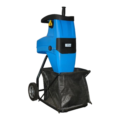
Brill 2000 ESK User manual

Leise-Häcksler
Silent shredder
Broyeur silencieux
Fluister hakselaar
Tichá drtička
Rozdrabniacz cichobieżny
Tystgående kompostkvarn
Biotrituratore silenzioso
Picadora de paja silenciosa
Triturador silencioso
2000 ESK
2300 ESK
y

Bedeutung der Symbole
Meaning of symbols
Signification des symboles
Betekenis van de symbolen
Význam symbolů
Znaczenie symboli
Symboler
Significato dei simboli
Significado de los símbolos
Significado dos símbolos
Achtung! Vor Inbetriebnahme Gebrauchsanweisung lesen!
Warning! Read instruction handbook!
Attention ! Merci de lire attentivement le mode d’emploi
avant d’utiliser cet appareil !
Let op! Voor ingebruikname gebruiksaanwijzing doorlezen!
Pozor! Před uvedením do provozu přečtěte návod k obsluze!
Uwaga! Przed uruchomieniem przeczytać instrukcję obsługi!
Observera ! Läs bruksanvisningen före användning!
Attenzione! Prima di mettere in funzione l'apparecchio, leggete le
istruzioni per l'uso!
Atención: ¡Lea las instrucciones de uso antes de la puesta en
marcha!
Atenção! Antes da colocação em funcionamento, leia o manual do
utilizador!
Vor Arbeiten am Schneidwerkzeug Netzstecker ziehen!
Before maintenance, disconnect the plug from the mains!
Débranchez l’appareil avant toute intervention sur le système
de coupe !
Voor werkzaamheden aan de snijinrichting, stekker uit het
stopcontact halen!
Před prací na řezném nástroji vytáhněte zástrčku!
Przed rozpoczęciem prac przy elementach tnących wyciągnąć
wtyczkę z sieci!
Dra ur eluttaget innan Du rengör eller justerar klingan!
Staccate la spina prima di effettuare lavori sul cilindro a coltelli!
¡Desconecte el enchufe antes de trabajar con el mecanismo
de corte!
Antes de trabalhar numa ferramenta de corte, desligue a ficha da
tomada!
Augen- und Gehörschutz tragen!
Wear eye and hearing protectors!
Portez des lunettes de protection ainsi qu’un casque anti-bruit.
Draag oog- en gehoorbescherming!
Noste chrániče zraku a sluchu!
Używać sprzętu ochrony oczu i słuchu!
Använd skydd för ögon- och öronskydd!
Indossate occhiali protettivi e cuffie salvatimpani!
¡Lleve protegidos los ojos y los oídos!
Use óculos de protecção e protecção auditiva!

3
Achtung, Gefahr! Umlaufende Schneidwerkzeuge!
Warning! Rotating tools!
Attention ! Danger ! Système de coupe à rotation.
Let op! Gevaar! Roterende snij-inrichting!
Pozor, nebezpečí! Rotační řezné nástroje!
Uwaga, niebezpieczeństwo! Wirujące narzędzia tnące!
Observera ! Roterade vass klinga!
Attenzione, pericolo! Cilindro a coltelli rotante!
¡Atención, peligro! ¡Mecanismos de corte en movimiento!
Atenção! Perigo! Ferramentas de corte de gume em toda a volta!
Dritte aus dem Gefahrenbereich fernhalten!
Keep bystanders away!
Maintenez tout tiers hors de la zone de travail !
Zorg ervoor dat derden buiten de gevarenzone blijven!
Udržujte nepovolané mimo nebezpečnou oblast!
Nie dopuszczać osób trzecich do strefy zagrożenia!
Se till att inga barn eller obehörig befinner sig i riskområdet!
Tenete lontane terze persone dalla zona di pericolo!
¡No debe haber terceras personas dentro de la zona de peligro!
Mantenha terceiros afastados da zona perigosa!
Achtung, Gefahr! Hände und Füße von Öffnungen
fernhalten, während die Maschine in Betrieb ist.
Danger! Keep hands and feet out of openings while machine
is running.
Attention – danger ! Tenez mains et pieds éloignés des ouvertures
pendant le fonctionnement de l’appareil.
Let op! Gevaar! Houdt handen en voeten weg bij de openingen
als de machine loopt.
Pozor, nebezpečí! Pokud je stroj v provozu, udržujte ruce
a nohy mimo otvory.
Uwaga, niebezpieczeństwo! Nie zbliżać rąk i nóg do otworów
podczas pracy maszyny.
Observera! Håll inga kroppsdelar (händer, fötter) vid öppningarna
under användning.
Attenzione, pericolo! Tenete mani e piedi lontani dalle aperture
durante il funzionamento della macchina.
¡Atención, peligro! Mantenga las manos y los pies retirados
de los orificios mientras la máquina esté en movimiento.
Atenção! Perigo! Mantenha mãos e pés afastados enquanto
a máquina estiver em funcionamento.

4
1
2
1
4
3
5
6
7
2
3
1
2
3
4
2
1
9 8 7 6 5 4 3 2 1 10

5
2000 ESK 2300 ESK 5
44
3
5
51
1
2
2
8
3
2
1
6 7

6
D
Bitte lesen Sie diese Gebrauchsanweisung vor
Montage und Inbetriebnahme Ihres Gerätes.
Beim Lesen der Gebrauchsanweisung
Umschlagseite herausklappen.
1. Ordnungsgemäßer Gebrauch 9
2. Hinweise zur Gebrauchsanweisung 9
3. Technische Daten
(siehe Ergänzung zur Gebrauchsanweisung)
4. Zusammenbauanleitung 9
5. Sicherheits- und Warnhinweise 10
6. Inbetriebnahme 10
7. Hinweise zum richtigen Häckseln 11
8. Wartung am Messerwerk 12
9. Wartung, Pflege, Aufbewahrung 12
10. Behebung von Störungen 13
Garantie 13
EU-Konformitätserklärung
(siehe Ergänzung zur Gebrauchsanweisung)
GB
Please read these operating instructions
before assembling and using your machine.
Fold out the cover when reading these
instructions.
1. Proper use 14
2. Information on the instructions for use 14
3. Technical data
(see Supplement to Operating Instructions)
4. Assembly instructions 15
5. Information on safety and hazards 15
6. Starting up 16
7. Information on the correct
cutting procedure 17
8. Maintenance of the blade assembly 17
9. Maintaining, caring for, and
treating the shredder 17
10. Remedying malfunctions 18
Guarantee 19
EU Certificate of Conformity
(see Supplement to Operating Instructions)
F
Nous vous remercions de bien vouloir lire
attentivement ce mode d’emploi avant
le montage et l’utilisation de votre broyeur.
Dépliez le 2° volet de la couverture pour avoir
les illustrations sous les yeux pendant la lecture
du mode d’emploi.
1. Utilisation dans les règles de l’art 19
2. Remarques concernant les instructions
de service 20
3. Données techniques
(voir Complément au mode d´emploi)
4. Instructions de montage 20
5. Instructions de sécurité et de prévention 21
6. Mise en service 21
7. Instructions pour un hachage correct 22
8. Entretien du bloc de coupe 23
9. Entretien, maintenance et entreposage 23
10. Réparation des pannes 23
Garantie 24
Certificat de conformité aux
directives européennes
(voir Complément au mode d´emploi)
NL
Lees deze gebruiksaanwijzing voor de
montage en ingebruikname von het apparaat
zorgvuldig door.
Klap de omslagzijde uit bij het lezen van de
gebruiksaanwijzing.
1. Regelmatig gebruik 25
2. Aanwijzingen bij de gebruiks-
handleiding 25
3. Technische gegevens
(zie Aanvulling op de gebruiksaanwijzing)
4. Montagehandleiding 25
5. Veiligheids- en waarschuwings-
voorschriften 26
6. Inbedrijfstelling 27
7. Aanwijzing voor een correcte
manier van hakselen 27
8. Onderhoud aan het messenwerk 28
9. Onderhoud, service, opslag 28
10. Verhelpen van storingen 29
Garantie 30
EU-overeenstemmingsverklaring
(zie Aanvulling op de gebruiksaanwijzing)
Inhaltsverzeichnis – Contents – Sommaire – Inhoudsopgave

7
CZ
Před montáží svého zařízení a jeho
uvedením do provozu přečtěte, prosím,
tento návod k obsluze.
Při čtení návodu k obsluze odklopte
stranu obalu.
1. Řádné používání 30
2. Pokyny k návodu k obsluze 31
3. Technická data
(viz – Dodatek k návodu k použití)
4. Návod k montáži 31
5. Bezpečnostní pokyny a upozornění 32
6. Uvedení do provozu 32
7. Pokyny ke správnému drcení 33
8. Údržba řezného ústrojí 33
9. Údržba, ošetřování, ukládání 34
10. Odstranění poruch 34
Prohlášení o záruce 35
Prohlášení o shodě EU
(viz – Dodatek k návodu k použití)
PL
Przed montażem i uruchomieniem
urządzenia należy przeczytać niniejszą
instrukcję obsługi.
Podczas czytania instrukcji obsługi rozłożyć
okładkę.
1. Prawidłowa eksploatacja 36
2. Wskazówki dotyczące instrukcji obsługi 36
3. Dane techniczne
(patrz Dodatek do instrukcji obsługi)
4. Instrukcja montażu 36
5. Zasady bezpieczeństwa i ostrzeżenia 37
6. Uruchomienie 38
7. Wskazówki dotyczące prawidłowego
rozdrabniania 39
8. Konserwacja mechanizmu tnącego 39
9. Konserwacja, pielęgnacja,
przechowywanie 39
10. Usuwanie usterek 40
Gwarancja 41
Deklaracja zgodności Unii Europejskiej
(patrz Dodatek do instrukcji obsługi)
S
Läs omsorgsfullt igenom bruksanvisningen
före montering och användning.
Vik ut omslagssidan när Du läser
bruksanvisningen.
1. Avsedd användning 42
2. Anmärkningar för bruksanvisning 42
3. Tekniska data
(se Tillägg till bruksanvisning)
4. Monteringsanvisning 42
5. Säkerhets- och varningsanvisningar 43
6. Idrifttagning 43
7. Anvisningar för korrekt hantering 44
8. Underhåll av knivarna 45
9. Underhåll, skötsel, förvaring 45
10. Felsökning 45
Garanti 46
EU Tillverkardeklaration
(se Tillägg till bruksanvisning)
I
Prima di montare e mettere in funzione il vostro
nuovo biotrituratore, siete pregati di leggere
attentamente le presenti istruzioni per l'uso.
Non dimenticate di consultare anche la pagina
pieghevole.
1. Impiego secondo destinazione 47
2. Note sulle istruzioni per l'uso 47
3. Dati tecnici
(vedi il Aggiunta alle istruzioni per l´uso)
4. Istruzioni di montaggio 47
5. Avvertenze di sicurezza e pericolo 48
6. Messa in esercizio 48
7. Avvertenze per una corretta
triturazione 49
8. Manutenzione del cilindro a coltelli 50
9. Manutenzione, pulizia,
conservazione 50
10. Eliminazione dei guasti 51
Garanzia 52
Dichiarazione di conformità
alle norme UE
(vedi il Aggiunta alle istruzioni per l´uso)
Obsah – Spis treści – Innehållsförteckning – Indice

8
E
Antes de montar la herramienta y de ponerla en
marcha lea estas instrucciones de uso.
Cuando lea las instrucciones de uso, despliegue
la página plegable.
1. Uso previsto 52
2. Advertencias sobre las
instrucciones de uso 53
3. Datos técnicos
(véase el Indicación adicional al manual de instrucciones)
4. Instrucciones de montaje 53
5. Instrucciones de seguridad
y advertencias 54
6. Puesta en servicio 54
7. Instrucciones para picar
correctamente 55
8. Mantenimiento del mecanismo
de corte 56
9. Mantenimiento, conservación
y almacenamiento 56
10. Solución de averías 56
Garantía 57
Declaración de conformidad de la UE
(véase el Indicación adicional al manual de instrucciones)
P
Leia este manual do utilizador antes de montar
e pôr a funcionar o seu aparelho.
Ao ler o manual do utilizador desdobre
a capa.
1. Utilização para os fins previstos 58
2. Notas relativas ao manual
do utilizador 58
3. Dados técnicos
(ver Supplemento às Instruções de utilização)
4. Instruções de montagem 59
5. Instruções de segurança
e indicações de aviso 59
6. Colocação em funcionamento 60
7. Indicações sobre como triturar
correctamente 61
8. Manutenção do mecanismo
de corte 61
9. Manutenção, cuidados,
armazenamento 61
10. Eliminação de falhas 62
Garantia 63
Certificado de Conformidade da UE
(ver Supplemento às Instruções de utilização)
Indice de materias – Índice

9
D
9
Die BRILL Häcksler sind für die
private Nutzung im Haus- und
Hobbygarten geeignet.
Als Häcksler für den privaten
Haus- und Hobbygarten werden
solche Geräte angesehen, die
nicht in öffentlichen Anlagen,
Parks, Sportstätten sowie in der
Land- und Forstwirtschaft ein-
gesetzt werden.
Die Einhaltung der vom Hersteller
beigefügten Gebrauchsanwei-
sung ist Voraussetzung für den
ordnungsgemäßen Gebrauch
der Häcksler.
Die Gebrauchsanweisung
enthält auch die Betriebs-,
Wartungs- und Instandhaltungs-
bedingungen.
Die Häcksler sind zum Zerklei-
nern von organischen Stoffen,
z.B. Pflanzenresten, die im
Haus- und Hobbygarten anfallen,
geeignet.
AAchtung! Die Garten-
geräte sind nicht geeignet,
um Gartenerde aufzubereiten
und dürfen niemals verwendet
werden, um Metallteile zu
zerkleinern.
Verletzungsgefahr!
Lesen Sie die Gebrauchsanwei-
sung sorgfältig. Beachten Sie die
Hinweise in dieser Gebrauchs-
anweisung. Machen Sie sich
anhand dieser Gebrauchsanwei-
sung mit den Betätigungsteilen
und dem richtigen Gebrauch
des Häckslers vertraut.
AAus Sicherheitsgründen
dürfen Jugendliche unter
16 Jahren sowie Personen, die
mit der Gebrauchsanweisung
nicht vertraut sind, diesen
Häcksler nicht benutzen.
Bewahren Sie diese Gebrauchs-
anweisung sorgfältig auf.
2. Hinweise zur Gebrauchsanweisung
(siehe Ergänzung zur Gebrauchs-
anweisung)
3. Technische Daten
Leise-Häcksler 2000 ESK / 2300 ESK
1. Ordnungsgemäßer Gebrauch
Kontrolle auf Vollständigkeit
Der Verpackungskarton enthält
folgende Teile:
.Fahrwerk
.Zwei Laufräder mit Radkappen
.Motor mit Getriebe
und Messerwerk
.Einfüllrohr
.Einfülltrichter
.Querträger
.Montagebeutel mit Schrauben
und Werkzeug, Gebrauchs-
anweisung mit Garantiekarte,
Servicestationen-Verzeichnis.
Montage des Häckslers
Die Montage der Laufräder
(Bild 1)
Auf Sechskantschraube (Pos. 1)
die Scheibe (Pos. 2) und das
Distanzrohr (Pos. 3) aufschieben
und in Radnabe (Pos. 4) ein-
führen. Anschließend Scheibe
(Pos. 5) auf Schraube (Pos. 1)
schieben und die Baugruppe
komplett in die Bohrung (Pos. 6)
des Fahrwerks einführen. Bau-
gruppe mit Scheibe (Pos. 7),
Federring (Pos. 8) und Sechs-
kantmutter (Pos. 9) verschrauben.
Nach erfolgter Radmontage die
Radkappe (Pos. 10) aufdrücken.
Montage des Motorblocks
(Bild 2)
Fahrwerk (Pos. 1) wie abgebildet
auf die Rückseite legen. Motor-
block (Pos. 2) wie abgebildet
aufstellen. Schaltstift (Pos. 3) wie
abgebildet in Pfeilrichtung in den
Kreuzschlitz des Motorblocks
(Pos. 2) einschieben. Motorblock
wie folgt mit Fahrwerk verschrau-
ben: Zwei Schrauben (Pos. 4)
wie abgebildet einsetzen und an-
ziehen. Lange Schraube (Pos. 5)
mit Scheibe (Pos. 6) versehen
und wie abgebildet montieren.
Lange Blechschraube (Pos. 7)
wie abgebildet montieren.
4. Zusammenbauanleitung

10
D
ADer Häcksler muss auf
ebenem und festem Unter-
grund standsicher aufgebaut
werden und darf während des
Betriebs nicht gekippt oder
schräggestellt werden.
ATragen Sie immer Hand-
schuhe und Schutzbrille,
wenn Sie mit dem Häcksler
arbeiten.
Keine Steine, Erde, Gläser, Texti-
lien, Kunststoffe oder Metallteile
in das Gerät einfüllen, denn die-
se Materialien führen zu starken
Beschädigungen des Schneid-
werkzeuges. Bei angeschlosse-
nem Gerät nicht in den Auswurf-
schacht greifen.
Bei Stillsetzen des Schneidwerkes
kein Häckselgut mehr einfüllen.
Die Netzanschlussdose muss
mit mindestens 16 Ampere abge-
sichert sein.
Bedienung des Gerätes
Anbringen der Anschlussleitung:
Anschlussleitung zuerst mit dem
Stecker am Häcksler verbinden.
6. Inbetriebnahme
ABenutzen Sie den Häcksler
nicht während Personen
(besonders Kinder) oder Tiere in
unmittelbarer Nähe sind. Der
Benutzer ist für Schäden verant-
wortlich.
Benutzen Sie den Häcksler
niemals mit beschädigten
Schutzeinrichtungen.
Arbeiten Sie nur bei ausreichen-
den Sichtverhältnissen.
Umlaufendes Werkzeug!
Werkzeug läuft nach!
Verletzungsgefahr für die
Finger!
Beim Arbeiten muss festes Schuh-
werk, Handschuhe und eine
Sicherheitsbrille getragen werden.
Das am Häcksler außen instal-
lierte Anschlusskabel muss
regelmäßig auf Anzeichen von
Beschädigungen und Alterungen
(Brüchigkeit) untersucht und darf
nur in einwandfreiem Zustand
benutzt werden.
Für den Anschluss des Häckslers
sind bei Verlängerungsleitungen
ab 2 m Länge mindestens Lei-
tungsarten zu verwenden, die
nicht leichter sind als H07 RNF
(3 x 1,5 mm2) nach DIN VDE
0620.
Die Kupplungen der Anschluss-
kabel müssen aus Gummi
oder gummiüberzogen sein
und der Norm DIN VDE 0620
entsprechen.
Benutzen Sie FI-Sicherheitsschal-
ter mit maximal 30 mA Auslöse-
fehlerstrom oder ähnliche Schutz-
einrichtungen.
Die vom Hersteller am Gerät
installierten Schalteinrichtungen
dürfen nicht entfernt oder über-
brückt werden.
Ortsveränderliche Geräte,
die im Freien verwendet
werden, müssen über Fehler-
stromschutzschalter ange-
schlossen werden (gilt nur für die
Schweiz).
Die Kupplungssteckdose einer
Verlängerungsleitung muss
spritzwassergeschützt sein
(gilt nur für Österreich).
5. Sicherheits- und Warnhinweise
Montage des Querträgers
(Bild 3)
Querträger (Pos. 1) über Bohrun-
gen im Fahrwerk positionieren
und mit 4 kurzen Blechschrauben
(Pos. 2) montieren. Kunststoff-
kappen (Pos. 3) in die Bohrun-
gen des Fahrwerks von unten
einsetzen.
Einschieben des Auffang-
behälters (Bild 4)
Auffangbehälter vorne auf die
Laufschiene (Pos. 1) aufsetzen
und vollständig einschieben.
Der Häcksler kann nur mit voll-
ständig eingeschobenem Auf-
fangbehälter in Betrieb genom-
men werden. Einfüllrohr (Bild 5,
Pos. 1) auf Messerwerköffnung
aufsetzen und mit Schrauben
(Bild 5, Pos. 2) am Gehäuse ver-
schrauben.
Montage des Einfülltrichters
2000 ESK (Bild 5)
Die drei Vierkantmuttern (Bild 5,
Pos. 3) in die Aufnahmen des
Einfüllrohres einsetzen. Einfüll-
trichter (Bild 5, Pos. 4) aufsetzen
und mit Schrauben (Bild 5,
Pos. 5) am Einfüllrohr befestigen.
Montage des Einfülltrichters
2300 ESK (Bild 5)
Einfülltrichter (Pos. 4) auf Ein-
füllrohr (Pos. 1) aufsetzen. Die
Schrauben (Pos. 5) von innen
einsetzen und von außen mit
Muttern (Pos. 5) verschrauben.
AVor der Benutzung ist stets
eine Sichtprüfung vorzu-
nehmen, um festzustellen, dass
Muttern, Bolzen und Arbeits-
werkzeug nicht abgenutzt oder
beschädigt sind. Abgenutzte oder
beschädigte Teile sind zu erset-
zen. Die Einbauhinweise des Her-
stellers sind zu beachten.


11
D
Danach die Anschlussleitung an
die Netzspannung anschließen.
ADas Kabel nicht über den
Einwurf oder unter den
Auswurf führen.
ABeim Auslegen der An-
schlussleitung darauf ach-
ten, dass sie nicht durch Tür-
oder Fensterspalten gequetscht
wird. Anschlussleitung nicht am
Kabel, sondern immer nur am
Stecker bzw. Kupplungsgehäuse
aus der Steckdose ziehen.
Betrieb
ADer Häcksler kann nur mit
vollständig eingeschobe-
nem Auffangbehälter in Betrieb
genommen werden.
Den Drehrichtungsschalter der
Messerwalze nach rechts (Bild 6,
Pos. 1) stellen. Danach über den
Druckschalter (Bild 6, Pos. 2) das
Gerät einschalten. Jetzt kann
Häckselgut bis zu einer Stärke
von 30 mm (2000 ESK) und
40 mm (2300 ESK) zugeführt
werden. Das Häckselgut wird
selbsttätig eingezogen.
Die Messerwalze kann durch
Fremdkörper, zu viel Häcksel-
gut oder durch zu dicke Äste
blockiert werden. Um die
Blockierung zu lösen, wird der
Drehrichtungsschalter (Bild 7,
Pos. 1) auf Rückwärtslauf der
Messerwalze gestellt und der
Druckschalter (Bild 7, Pos. 2)
wieder eingeschaltet. Jetzt wird
das Häckselgut nach oben frei-
gegeben. Wird bei einer Total-
blockade das Häckselgut nicht
freigegeben, so muss die innen-
liegende Aluminiumgegenplatte
vom Messerwerk mittels der
Einstellschraube (Bild 8, Pos. 1)
gelöst werden.
Hierzu wird die Kontermutter
(Bild 8, Pos. 2) gelöst und die
Einstellschraube soweit nach
links gedreht, bis sich die Total-
blockade über den Rückwärts-
lauf der Messerwalze löst. Nach
Lösung der Blockierung wird der
Häcksler über den Drehrichtungs-
schalter wieder auf den Normal-
betrieb (Bild 6, Pos. 1) einge-
stellt. Stillstand der Messerwalze
abwarten und den Häcksler
wieder über den Druckschalter
(Bild 6, Pos. 2) in Betrieb neh-
men. Wurde bei einer Total-
blockade die Aluminiumgegen-
platte gelöst, so muss diese
wieder, wie in Punkt 8 „Wartung
am Messerwerk“ beschrieben,
justiert werden.
Bei einer abrupten Blockierung
der Messerwalze besteht die
Möglichkeit, dass sich die Dreh-
richtung der Messerwalze selbst-
ständig ändert und das Häcksel-
gut nach oben freigegeben
wird. In diesem Fall wird der
Häcksler über den Druckschalter
(Bild 6, Pos. 2) ausgeschaltet,
der Stillstand der Messerwalze
abgewartet und danach über
den Druckschalter wieder ein-
geschaltet.
Überlastschutz
Der Häcksler ist mit einem Über-
lastschutzschalter ausgestattet,
der den Motor bei starker
Überlastung, insbesondere bei
Blockade der Messerwalze,
nach ca. 8 – 12 Sekunden
abschaltet. Nach dem selbst-
ständigen Abschalten des
Gerätes durch den Überlast-
schutzschalter ist eine
Abkühlzeit von mindestens
5 Minuten einzuhalten.
Abstellen
Zum Abstellen den Druckschalter
(Bild 6, Pos. 2) auf 0 (STOP)
stellen.
Achtung!
Messerwalze läuft nach.
ADas Kabel ist beim Arbei-
ten von der Einfüll- und
Auswurfeinrichtung fernzuhalten.
ABeim Einschalten des
Motors muss der Häcksler
vorschriftsmäßig geschlossen
sein. Der Einfülltrichter muss
montiert und der Auffangbehäl-
ter muss vollständig eingescho-
ben sein. Beim Verlassen des
Häckslers ist der Motor stillzu-
setzen und der Netzstecker zu
ziehen.
AWird der Häcksler an
einen anderen Standort
transportiert, ist der Motor vor-
her abzustellen, der Netzstecker
zu ziehen und der Stillstand des
Messerwerkes abzuwarten.
ATragen Sie immer Hand-
schuhe und Schutzbrille,
wenn Sie mit dem Häcksler
arbeiten.
Besondere Hinweise
zum Häckseln
Die BRILL Häcksler sind keine
Muser und dadurch nur bedingt
einsetzbar zum Zerkleinern von
weichen und sehr safthaltigen
Abfällen (z. B. Kernobst, nassen
Pflanzenabfällen). Diese Materia-
lien sollten direkt kompostiert
werden, denn sie verdichten
sehr rasch von selbst. Bei einem
Zerkleinern der oben genannten
Abfälle würde ansonsten eine
luftundurchlässige, zu Fäulnis
führende und übelriechende
Masse entstehen, die sich auf
eine gute Rotte nachteilig aus-
wirkt.
7. Hinweise zum richtigen Häckseln

12
D
Die Aluminium-Gegenplatte
der Messerwalze unterliegt
einem natürlichen Verschleiß,
der nachjustiert werden muss,
um Schäden am Messerwerk
vorzubeugen.
Dieses Nachjustieren ist dann
vorzunehmen, wenn das Häcksel-
gut nicht vollständig durchtrennt
wird. Bei laufendem Motor (Dreh-
richtungsschalter Bild 6, Pos. 1)
wird die Kontermutter (Bild 8,
Pos. 2) mit dem beiliegenden
Gabelschlüssel (13 mm) gelöst
und die Einstellschraube (Bild 8,
Pos. 1) von Hand um jeweils
1/6 Umdrehung nach rechts
gedreht, bis ein leichtes Schleif-
geräusch zu hören ist und kurz-
zeitig feine Aluminiumspäne
aus dem Auswurfkanal fallen.
Danach die Kontermutter wieder
anziehen. Das Häckselgut wird
wieder vollständig durchtrennt.
8. Wartung am Messerwerk
AWartungs- und Reinigungs-
arbeiten am Häcksler
sowie das Abnehmen der Schutz-
einrichtungen dürfen nur bei still-
gesetztem Motor und abgeschal-
tetem Messerwerk und nur wenn
der Netzstecker herausgezogen
ist, vorgenommen werden.
Der Häcksler darf nicht mit
fließendem Wasser, insbesondere
nicht unter Hochdruck, gereinigt
werden.
Abgenutztes oder beschäd-
igtes Messerwerk ist nur vom
autorisierten Fachmann zu
ersetzen.
Wartung
Allgemeines
Die Wartung umfasst Arbeiten,
die den Häcksler in einwand-
freiem Betriebszustand erhalten.
Durch regelmäßige Überprüfung
(fester Sitz von Schraubverbin-
dungen, Risse, Beschädigungen)
und Auswechseln schadhafter
und abgenutzter Teile wird
Unfällen und Geräteausfällen
vorgebeugt. Das Messerwerk
muss turnusmäßig durch die Boh-
rung (Bild 8, Pos. 3) mit Öl (z. B.
WD 40) geschmiert werden.
Der Motor und das Getriebe
des Häckslers sind wartungsfrei.
AVor Beginn jeder War-
tungstätigkeit Motor
abstellen und Netzstecker
ziehen. Zur Vermeidung von
Verletzungen Schutzhand-
schuhe anziehen.
Pflege
Direkt nach dem Häckseln
Schmutz und Häckselreste ent-
fernen. Hierzu eine weiche
Bürste oder einen Lappen ver-
wenden (Schutzhandschuhe
tragen).
Aufbewahrung
(Überwinterung)
Den Häcksler immer in einem
trockenen, geschlossenen Raum
abstellen. Zusätzlich zur oben
genannten Pflege den Trichter
(siehe Punkt 4, Montage –
Bild 5, Pos. 1) demontieren
und das so freigelegte Messer-
werk mit einem biologisch ab-
baubaren, ölhaltigen Pflege-
spray einsprühen (z. B. WD 40).
9. Wartung, Pflege, Aufbewahrung
Die BRILL Häcksler zerkleinern
bestens langstielige, harte oder
bereits getrocknete Stängel von
Blumen, Stauden, Sträuchern
und Baumschnitt.
Setzt sich der Einfülltrichter
oder die Messerwalze durch zu
viel nasses Material zu, so kann
durch das Verarbeiten
von Astmaterial die Verstopfung
meistens wieder behoben wer-
den. Weiches Material sollte
deshalb immer mit Ästen im
Wechsel verarbeitet werden.
Beachten Sie, dass der Auffang-
behälter regelmäßig entleert
werden muss (Füllstandskontrolle
durch Sichtöffnungen – Bild 4,
Pos. 2), da bei Überfüllung ein
Rückstau von Häckselgut im
Messerwerk erfolgen kann.
Auffangbehälter zum Entleeren
nach vorne aus dem Fahrwerk
herausziehen, entleeren und
vollständig in die Laufschiene
des Fahrwerks wieder einschie-
ben (Bild 4, Pos. 1).

13
D
Störungstabelle
Störung Mögliche Ursache Behebung
Motor läuft nicht an. Drehrichtungsschalter in Null- Drehrichtungsschalter in richtige
Position. Position stellen (siehe Bild 6,
Pos. 1).
Auffangbehälter fehlt, bzw. ist Auffangbehälter vollständig
nicht vollständig eingeschoben. einschieben.
Häcksler zieht Häckselgut Drehrichtung des Messerwerkes Drehrichtungsschalter in richtige
nicht ein. falsch. Position bringen (Bild 6, Pos. 1).
Auffangbehälter überfüllt Auffangbehälter entleeren.
(Rückstau im Messerwerk).
Häckselgut wird zu wenig Aluminiumgegenplatte im Nachjustierung der Aluminium-
durchtrennt. Messerwerk nicht richtig ein- gegenplatte (siehe Punkt 8,
gestellt. Wartung am Messerwerk).
Motor setzt aus. Überlastschutz hat wegen Nach etwa 5 Minuten Abkühl-
ständiger Überlastung oder zeit kann der Motor wieder
Blockierung des Messerwerkes eingeschaltet werden.
angesprochen.
Abnorme Geräusche. Schrauben am Motor, seiner Schrauben nachziehen.
Klappern am Gerät. Befestigung oder dem Fahrwerk
lose.
Allgemeines
Störungen treten meistens nur
auf, wenn das Gerät nicht richtig
behandelt, gepflegt und gewartet
wurde.
Die nachstehende Tabelle
enthält mögliche Störungen und
deren Beseitigung. Bei weiteren
Störungen ist die nächste
BRILL Servicestation einzu-
schalten.
AReparaturen, die Fach-
kenntnisse erfordern,
dürfen nur von einem autorisier-
ten Fachmann durchgeführt
werden (siehe BRILL Service-
stationen-Verzeichnis).
ABeschädigte Netzanschluss-
leitungen dürfen nur von
einer BRILL Servicestation aus-
getauscht werden.
AAus Sicherheitsgründen
sind nur Original BRILL
Ersatzteile oder vom Hersteller
freigegebene Teile zu verwenden.
10. Behebung von Störungen
Wir weisen ausdrücklich darauf
hin, dass wir nach dem Produkt-
haftungsgesetz nicht für durch
unsere Geräte hervorgerufene
Schäden einzustehen haben, so-
fern diese durch unsachgemäße
Reparatur verursacht oder bei
einem Teileaustausch nicht unsere
Original-BRILL-Teile oder von uns
freigegebene Teile verwendet
werden und die Reparatur nicht
vom BRILL Kundenservice oder
dem autorisierten Fachmann
durchgeführt wird. Entsprechen-
des gilt für Ergänzungsteile und
Zubehör.
Der Hersteller gewährt für seine
Produkte bei ausschließlich
privater Nutzung 24 Monate
Garantie (ab Kaufdatum). Die
gesetzlichen Gewährleistungs-
ansprüche bleiben davon un-
berührt. Die Garantieleistung
bezieht sich auf alle wesent-
lichen Mängel der Produkte,
die nachweislich auf Material-
oder Fabrikationsfehler zurück-
zuführen sind. Sie erfolgt nach
unserem Ermessen durch die
Ersatzlieferung eines einwand-
freien Produktes oder die kosten-
lose Nachbesserung des Produk-
tes, wenn folgende Voraussetzun-
gen gewährleistet sind:
Garantie

14
D
GB
Carefully read the instructions
for use and note the information.
Using these instructions get
to know fully the operating
components and the correct use
of the shredder.
AFor safety reasons persons
under the age of sixteen
and those who are unacquainted
with the instructions for use may
not use the shredder.
Please keep these operating
instructions in a safe place.
2. Information on the instructions for use
.Produkt ist bei Gefahrüber-
gang frei von Rechtsmängeln
übergeben worden.
.Ein Original-Kaufbeleg mit
Käuferadresse, Kaufdatum,
Typ und Produktbezeichnung
liegt als Kaufnachweis vor.
Der Kaufort liegt innerhalb
der EU.
.Das Produkt wurde sach-
gemäß und entsprechend
den Empfehlungen in der
Gebrauchsanweisung behan-
delt. Die Wartung und Reini-
gung des Produktes nach den
Angaben der Gebrauchs-
anweisung ist unabdingbar.
Es wurde weder vom Käufer
noch von einem nicht auto-
risierten Dritten versucht, das
Produkt zu zerlegen bzw. zu
reparieren.
.Es ist sicherzustellen, dass aus-
schließlich Original-Ersatzteile
und Original-Zubehör oder
vom Hersteller freigegebene
Teile verwendet werden.
Bei einem Einsatz von Nicht-
Original-Teilen oder Nicht-
Original-Zubehör sind Folge-
schäden und erhöhte Unfall-
gefahr nicht auszuschließen.
Diese Folgeschäden unterlie-
gen nicht der Garantie.
.Das Produkt muss direkt oder
ausreichend frankiert einer
autorisierten Servicestelle
übergeben bzw. zugeschickt
werden. Der Original-Kauf-
beleg ist dem Produkt beizu-
legen.
.Beschädigungen aufgrund von
Bedienerfehlern, nicht bestim-
mungsgemäßen Gebrauch,
Verwendung von ungeeigne-
ten, nicht originalen oder
freigegebenen Austausch-,
Ersatz- und Zubehörteilen
sowie nicht sachgemäß durch-
geführten Wartungs- und Rei-
nigungsarbeiten, können nicht
als Garantie anerkannt wer-
den.
Die Produkte enthalten ver-
schiedene Bauteile, die einem
gebrauchsbedingten Verschleiß
bzw. einer normalen Abnutzung
unterliegen. Diese Verschleiß-
teile sind nicht Bestandteil der
Garantie. Als Verschleißteile
werden produktabhängig im
Einzelnen folgende Bauteile
ausgeschlossen:
Messerwalze / Schneidplatte
Diese Hersteller-Garantie berührt
die gegenüber dem Händler /
Verkäufer bestehende Gewähr-
leistungsansprüche nicht.
BRILL shredders are suitable for
private use in gardens and
allotments.
Regarded, as shredders for
private gardens and allotments
are those units, which are not
employed in public grounds,
parks, sports grounds, and in
agriculture and forestry.
Adherence to the instructions
for use supplied by the manu-
facturer forms a requirement
for the proper use of the shred-
der.
The instructions for use also
contain the operating, mainte-
nance, and servicing require-
ments.
These shredders are suitable
for the cutting up of organic
substances, e.g. vegetable
waste, arising in the private
garden or allotment.
AAttention! The shredders
are not suitable, for ex-
ample, for preparing soil and
must never be used to chop
or cut metal parts. Danger of
injury!
Silent shredder 2000 ESK / 2300 ESK
1. Proper use

15
GB
15
(see Supplement to Operating
Instructions)
3. Technical data
ADo not use the shredder
when persons (especially
children) or animals are directly
nearby. The user shall be
liable for any damage or injury
incurred.
Never use the shredder when
the protecting devices are
damaged.
Only work in an area where you
have a good view of everything.
Rotating blade assembly!
Blade assembly lags!
Danger of injuries to the
fingers!
During the work, protective
shoes, gloves, and goggles are
to be worn.
The connecting cable installed on
the outside of the shredder must
be examined regularly for signs
of damage and aging (brittle-
ness) and may only be used in
a flawless condition.
When connecting the shredder
using extensions of 2 m in
length only those cables may
be used which are no lighter
than H07 RNF (3 x 1.5 mm2)
in accordance with DIN
VDE 0620.
Couplings to the connecting
cable must be of rubber or lined
with rubber and correspond to
the standard DIN VDE 0620.
Use residual current devices
with maximum 30 mA
actuating current or similar
safety devices.
5. Information on safety and hazards
Check contents for completeness
The box should contain the
following parts:
.Wheel frame
.Two wheels with hubcaps
.Motor with gearbox
and cutter unit
.Hopper tube
.Hopper top
.Crossbar
.Bag with nuts and bolts, tools,
instructions, guarantee card
and list of service centres.
Assembling the shredder
Assembling the wheels
(Fig. 1)
Push washer (item 2) and the
spacer tube (item 3) onto hex-
agonal bolt (item 1) and into
wheel hub (item 4). Then fit
washer (item 5) on bolt (item 1)
and insert the complete assembly
through hole in frame (item 6).
Fit washer (item 7), spring
washer (item 8) and nut (item 9)
onto axle assembly. Fit hubcap
(item 10) onto wheel.
Assembling the motor unit
(Fig. 2)
Place wheel frame (item 1) on
its back as shown. Stand motor
unit (item 2) on its end as shown.
Locate the control pin (item 3)
as shown in cross-shaped open-
ing in the motor unit housing
(item 2). Attach motor unit to
frame as follows: Fit two bolts
(item 4) and tighten as shown.
Place washer (item 6) on long
bolt (item 5) and fit as shown.
Fit bolt (item 7) as shown.
Assembling the crossbar
(Fig. 3)
Locate crossbar (item 1) over
holes in frame and fit with bolts
(item 2). Push plastic caps
(item 3) from bottom into holes
in frame.
Fitting the collector box
(Fig. 4)
Locate collector box on rails
(item 1) and push in fully. The
shredder will only run when
the collector box has been fully
pushed in. Locate the hopper
tube on cutter opening (Fig. 5,
item 1) and fit bolts to motor
unit (Fig. 5, item 2).
Assembling the hopper
2000 ESK (Fig. 5)
Fit the three square nuts (Fig. 5,
item 3) into the slots provided
in the hopper tube. Place hopper
top (Fig. 5, item 4) on hopper
tube and fit screws provided
(Fig. 5, item 5).
Assembling the hopper
2300 ESK (Fig. 5)
Place hopper top (item 4) on
hopper tube (item 1). Fit bolts
(item 5) from inside and nuts
(item 5) from outside.
AAlways conduct a visual
check before use to
establish whether any nuts,
bolts, and other parts are worn
or damaged. Worn or damaged
parts are to be replaced.
The manufacturer’s information
on installation is to be observed.
4. Assembly instructions

The switching devices installed
on the unit by the manufac-
turer may not be removed or
bridged.
Mobile units used outdoors
must be connected to a current-
operated earth-leakage circuit
breaker (applicable only in
Switzerland).
The coupling socket of the
extension cable must be pro-
tected against spraying water
(applicable only in Austria).
16
GB
AThe shredder must be
erected stably on even
and firm ground and may
not be tipped or otherwise tilted
during the cutting operation.
AAlways wear gloves and
protective goggles when
working with the shredder.
Do not introduce any stones,
earth, glass, textiles, plastic, or
metal into the unit for these
materials will cause serious
damage to the blades. Do
not reach into the eject tunnel
when the unit is connected.
Do not continue to feed the
unit when shutting down the
blade assembly. The mains
socket must be provided with
a min. 16 A fuse.
Operating the unit
Connecting the electrical supply;
first of all insert the plug of the
connecting cable into the shred-
der, then insert the connecting
cable into the mains socket.
ADo not lay the cable over
the feed or beneath the
eject.
APlease note when laying
the connecting cable that
it cannot be crushed in doors
or windows. Always disconnect
the connecting cable by
pulling the plug or connection
casing, and not the flex, from
the socket.
Operation
AThe shredder will only run
when the collector box has
been fully pushed in.
Set the rotary direction switch
for the blade cylinder to the right
(Fig. 6, item 1), then activate
the unit using the push button
(Fig. 6, item 2). Now the shred-
der can be fed with material
with a maximum thickness of
30 mm (2000 ESK) or 40 mm
(2300 ESK). The material will
be drawn in automatically.
Foreign matter, too much mate-
rial, or too thick branches can
block the knife blade assembly.
To remedy this problem the
rotary direction switch (Fig. 7,
item 1) is set to reverse rotation
of the blade cylinder and the
push button (Fig. 7, item 2)
again activated. The blade
assembly now frees itself by
pushing the material upwards.
If upon a total blockage the
mate-rial is not released, the
inside aluminium counter plate
has to be loosened from the
blade assembly by means of the
ad-justing screw (Fig. 8, item 1).
To do this, loosen the counter
nut (Fig. 8, item 2) and turn the
adjusting screw to the left until
the total blockage releases itself
by reverse rotation of the blade
assembly. Once the blockage
has been cleared the shredder
is again activated by the rotary
direction switch set to normal
operation (Fig. 6, item 1). Wait
until the blade assembly has
stopped rotating before restart-
ing the shredder with the push
button (Fig. 6, item 2). If the
aluminium counter plate was
unscrewed because of a total
blockage, it has to be re-
adjusted as mentioned in
“8. Maintenance of the blade
assembly”.
Upon an abrupt blockage of
the blade assembly it is possible
that the rotary direction of the
blade assembly will automatical-
ly reverse, thereby pushing the
material upwards. In this event
the shredder is switched off with
the push button (Fig. 6, item 2),
and then restarted with the push
button once the blade assembly
has stopped rotating.
Overload protection
The shredder is equipped with
an overload protection switch
which, with severe overloading
in particular when the blade
cylinder is blocked, deactivates
the motor after approx. eight
to twelve seconds. After the
independent deactivation of the
unit by the overload protection
switch, a cooling period of
at least five minutes is to be
observed.
Shutting down
To shut down the system, set the
push button (Fig. 6, item 2) to
0 (STOP).
Important! The blade cylinder is
still running!
6. Starting up

17
GB
AEnsure that the mains
cable is kept away from
feed and eject hoppers.
AIn accordance with the
regulations, before
switching on the motor the
shredder must be closed.
Feed hopper must be fitted.
The collector box must be fully
pushed in position. When
leaving the shredder the motor
is to be stopped and the mains
plug withdrawn.
ABefore the shredder is
transported to another
location, the motor is to be
stopped, the mains plug with-
drawn, and the blade assembly
still.
AAlways wear gloves
and protective goggles
when working with the
shredder.
Special information
on the cutting procedure
BRILL shredders are not general-
purpose grinders and hence are
only conditionally used for cut-
ting soft and succulent waste
(e.g. malaceous fruit, wet veg-
etable waste). These substances
should be directly composted
for they automatically become
very quickly compacted. Other-
wise, after the above wastes
have been cut, an air-tight,
odious mass leading to rotten-
ness would result which would
have a detrimental effect on
a good compost.
The BRILL shredder best cuts
long, hard, or dry stems of flow-
ers, shrubs, bushes, and tree
cuttings.
Should the feed funnel or the
blade cylinder seize owing to
too much wet material, this can
be remedied in most cases by
introducing branches. Soft
material and branches should
therefore always be processed
alternately.
The collector box must be emp-
tied regularly to avoid blocking
the cutter unit. (Level can be
inspected through opening –
Fig. 4, item 2). Overfilling will
cause the cutter unit to become
congested.
To empty collector box, pull
forward until box has cleared
the chassis. To re-insert, locate
collector on mounting rails
and push under cutter (Fig. 4,
item 1).
7. Information on the correct cutting procedure
The aluminium plate on the cutter
unit is subject to normal wear,
and must be adjusted to avoid
damage to the blade.
This re-adjustment is only then to
be performed when the material
for cutting is not completely cut
through. While the motor is
running (rotary direction Fig. 6,
item 1) the counter nut (Fig. 8,
item 2) is loosened with 13 mm
spanner supplied and adjusting
screw (Fig. 8, item 1) is turned
manually about 1/6 of a turn
clockwise, until a slight grinding
noise is heard and aluminium
swarf falls out of the eject chan-
nel for a short time. Finally
tighten the counter nut and the
shredder should now cut cor-
rectly.
8. Maintenance of the blade assembly
AMaintenance and cleaning
work on the shredder and
removal of the protective devices
may only be performed when
the motor has been shut down,
the blade assembly has stopped
rotating, and the mains plug has
been withdrawn.
The shredder may not be cleaned
with flowing water, especially
not under high pressure.
A worn or damaged blade
assembly is to be replaced only
by an authorised expert.
Maintenance
General
Maintenance includes all work
which keep the shredder in a
flawless state. Accidents and
equipment failure are prevented
by regular checks (firm seat of
screwed connections, cracks,
damage) and replacement of
faulty and worn parts. The cutter
unit should be lubricated regu-
larly, via the opening in the
casing (Fig. 8, item 3) using oil
like WD 40.
The motor and the transmission
of the shredder are maintenance
free.
AEach time before starting
maintenance work, switch
off the motor and withdraw
9. Maintaining, caring for, and treating the shredder

18
GB
General
Malfunctions mostly occur when
the unit has not been correctly
handled, treated, or mainte-
nanced. The following table
contains possible malfunctions
and their remedy. If the mal-
function persists, please contact
the next BRILL service station.
ARepair work requiring
specialist knowledge
may only be performed by an
authorised expert (see the list
of BRILL service stations).
ADamaged mains connec-
tion cables may only be
exchanged by a BRILL service
station.
AFor safety reasons original
BRILL spare parts or parts
approved of by the manufacturer
only may be used.
10. Remedying malfunctions
Table of malfunctions
Malfunction Possible cause Remedy
Motor does not start. Rotary direction switch set Set the rotary direction switch to
to zero. the correct position (see Fig. 6,
item 1).
Collector box missing or not Push collector box fully into
fully in position. position.
Shredder does not draw Rotary direction of the blade Set the rotary direction switch
through the material. assembly wrong. to the correct position (Fig. 6,
item 1).
Collector box too full Empty collector box.
(blade unit congested).
Material insufficiently cut Aluminium counter plate Re-adjust the aluminium counter
through. incorrectly set in the blade plate (see point 8, Maintenance
assembly. of the blade assembly).
Motor deactivates. Overload protection activated After a cooling time of approx.
owing to constant overloading 5 minutes, the motor can be
or blocking of the blade as- re-activated.
sembly.
Abnormal noises, Screws on the motor, its seat, Re-tighten screws.
unit knocks. or the frame is loose.
We explicitly state that, accord-
ing to the Product Liability Act,
we do not have to accept liability
for any damage caused by our
equipment if such damage was
caused by inadequate repairs or,
during the replacement of parts,
our original BRILL parts or parts
approved by us were not used
and the repairs were not carried
out by the BRILL technical service
department or the authorised
expert. The same also applies to
extras and accessories.
the mains plug. Wear protective
gloves to prevent injury.
Taking care of the shredder
Dirt and cut waste residue are
best removed directly after the
cutting operation. Use here a
soft brush or a cloth. (Always
wear protective gloves.)
Treatment (winterisation)
Always store the shredder in a
closed, dry room. In addition
to the above treatment, remove
the funnel (see point 4 of
Assembly – Fig. 5, item 1) and
apply a biologically degradable,
oil emulsive treatment spray to
the exposed blade assembly.
(For instance WD 40 oil.)

Le broyeur BRILL convient par-
faitement pour une utilisation
dans tous les jardins particuliers.
Comme broyeur pour le domaine
privé (jardins) sont considérés les
appareils qui ne peuvent pas
être utilisés dans des installations
publiques, parcs, terrains de
sport ainsi que dans l’agriculture
et la sylviculture.
Le respect des instructions de ser-
vice jointes par le fabricant est
la condition permettant une utili-
sation adéquate des broyeurs.
Les instructions de service
comprennent également les
conditions de fonctionnement,
d’entretien et de maintenance.
Les broyeurs sont conçus pour
couper des déchets organiques,
comme par exemple des résidus
de plantes, qui se produisent
dans les jardins.
AAttention ! Les broyeurs
ne sont pas appropriés au
traitement de la terre de jardin
par exemple, et ne doit jamais
être utilisé pour broyer entre
autres des éléments en métal.
Risque de blessures !
19
GB
F
The manufacturer warrants its
products for exclusively non-
commercial use for a period of
24 months from the date of
original purchase. This warranty
does not affect statutory warranty
claims. The warranty covers all
substantial faults of the product,
which are caused by defects in
material and workmanship. If a
product exhibits such a defect
we will, at our option, repair or
replace it without cost for parts
and labour provided the follow-
ing requirements are fulfilled:
.The product must have
been sold to the customer in
a legally correct way.
.The original receipt with the
customer’s address, date of
purchase, model and product
designation is presented as
proof of purchase. The product
must have been purchased
within the EC.
.The product was handled
properly and according to
the recommendations in the
operating instructions. It is
essential that the product has
been maintained and cleaned
according to the information in
the operating instructions.
No attempt to disassemble or
repair the product has been
made by either the buyer or an
unauthorized third party.
.It must be ensured that only
original replacement parts and
original accessories approved
by the manufacturer are used.
There may be an increased
risk of consequential damage
and accidents if non-original
parts or non-original acces-
sories are used. This warranty
does not cover consequential
damages.
.The product must be either
taken directly or sent with
postage paid to an authorised
service centre. The original
receipt must be sent with the
product.
.The warranty does not cover
damage from misuse, abuse,
use of unsuitable, non-original
or unauthorised interchange-
able parts, replacement parts
or accessories, as well as
improper maintenance and
cleaning.
The products contain various
components that are subject to
normal or use-related wear.
The warranty does not extend to
these wearing parts. In particular
the following components rela-
ting to this product are excluded:
blade cylinder / cutting plate.
The manufacturer warranty
does not affect existing warranty
claims between the customer
and the dealer / seller.
Warranty
Broyeur silencieux 2000 ESK / 2300 ESK
1. Utilisation dans les règles de l’art

20
F
Contrôle des pièces
L’emballage contient les pièces
suivantes :
.châssis de transport
.deux roues avec enjoliveurs
.moteur avec boîtier d’engre-
nage et ensemble de coupe
.tuyau de remplissage
.entonnoir de remplissage
.traverse
.sachet de montage avec
visserie et outils (kit), mode
d’emploi avec carte de garan-
tie, liste stations services.
Montage du broyeur
Montage des roues (fig.1)
Monter la rondelle (pos. 2) et le
cylindre d’écartement (pos. 3)
sur la vis à six pans (pos. 1)
et introduire l’ensemble dans
l’ouverture de la roue (pos. 4).
Ensuite, mettre la rondelle
(pos. 5) sur la vis de perçage
(pos. 1) et positionner l’en-
semble dans le trou de perçage
du châssis (pos. 6). Visser l’en-
semble avec la ron-delle (pos. 7),
rondelle ressort (pos. 8) et
l’écrou six pans (pos. 9). Après
l’assemblage, clipper l’enjoliveur
(pos. 10).
Montage du bloc moteur
(fig. 2)
Coucher le châssis sur le côté
(pos. 1), dresser le bloc moteur
(pos. 2) comme sur le schéma.
Monter le contact interrupteur
(pos. 3) selon schéma, dans
l’ouverture en croix du bloc
moteur (pos. 2). Assembler le
bloc moteur avec le châssis
comme suit, fixer et serrer les
2 vis (pos. 4). Monter et serrer
les vis longues (pos. 5) et ron-
delles (pos. 6) selon schéma.
Monter les vis (pos. 7) selon
schéma.
Montage de la traverse (fig. 3)
Positionner la traverse (pos. 1)
en regard des trous de perçage
du châssis et fixer avec des vis
(pos. 2). Mettre les capuchons
en plastique (pos. 3) par le bas,
dans les trous de perçage du
châssis.
Mise en place du bac de
récupération (fig. 4)
Introduire de bac de récupéra-
tion par l’avant sur les glissières
(pos. 1) et le pousser vers l’ar-
rière. Les broyeurs ne peuvent
être mis en route qu’avec le bac
de récupération engagé à fond.
Placer le tuyau de remplissage
sur l’ouverture de l’ensemble
de coupe (fig. 5, pos. 1) et
visser (fig. 5, pos. 2) sur le bloc
moteur.
Montage de l’entonnoir de rem-
plissage 2000 ESK (fig. 5)
Mettre les 3 écrous carrés
(fig. 5, pos. 3) dans les supports
du tuyau de remplissage.
Positionner l’entonnoir sur le
tuyau (fig. 5, pos. 4) et visser
(fig. 5, pos. 5) l’ensemble.
Montage de l’entonnoir de rem-
plissage 2300 ESK (fig. 5)
Mettre l’entonnoir (pos. 4) sur
le tuyau (pos. 1). Mettre les vis
(pos. 5) de l’intérieur et serrer
avec les écrous (pos. 5) de l’ex-
térieur.
AAvant l’utilisation, il faut
toujours procéder à un
contrôle visuel afin de constater
si les écrous, boulons et outils
de travail ne sont pas usés ou
endommagés. Des pièces usées
ou endommagées doivent être
remplacées. Tenir compte des
instructions de montage du fabri-
cant.
4. Instructions de montage
(voir Complément au mode
d´emploi)
3. Données techniques
Lisez attentivement les instruc-
tions de service. Tenez compte
des indications contenues dans
ces instructions.
Ces instructions de service vous
aideront à vous familiariser avec
les éléments de commande et
l’utilisation correcte des bro-
yeurs.
APour des raisons de sécu-
rité, des jeunes de moins
de 16 ans et des personnes qui
ne sont pas familiarisées avec les
instructions de service ne doivent
pas se servir de ces broyeurs.
Conservez ce mode d’emploi
précieusement.
2. Remarques concernant les instructions de service
This manual suits for next models
1
Table of contents
Languages:
Other Brill Paper Shredder manuals