Broadcast Devices SCA-200 Product manual

Broadcast Devices, Inc.
SCA-200 Dual 67 KHz SCA Generator
Technical Reference Manual
Broadcast Devices, Inc.
Tel. (914) 737-5032
Fax. (914) 736-6916
World Wide Web: www.Broadcast-Devices.com
Rev A. 11/19

2
Table of Contents
Introduction 3
I. Unpacking 3
II. Installation and Connections 3-4
III. Features and Operation 4
IV. Initial Operating Setup 4-5
SCA-200 Optional Programming Functions 5-6
Remote Control Connections 6
Analog Audio Input Connector Wiring 7
Serial RS232 Connector Wiring 7
V. Specifications 8
VI. Warranty 9

3
Introduction and Description
The SCA-200 Dual 67 KHz SCA Generator is a next generation approach to SCA generators
utilizing digital signal processing. The SCA-200 comprises of two totally independent 67 KHz SCA
generators in one chassis. Each generator has two XLR balanced inputs which are selectable via
the SCA-200 Windows application software. The unit features two independent outputs for each
generator. All setup adjustments are made via the APP as there are no physical controls or
switches on the front panel of the unit. Adjustment for input level, optional audio low pass filter,
pre emphasis and output level are all accomplished via the SCA-200 APP.
I. Unpacking
Carefully inspect the unit after unpacking and make certain that no damage has occurred during
shipping. If damage is noted, contact the shipper immediately and file a claim for damages. Each
unit is carefully packed and carries full insurance against damage. Inspect the packing list and
make sure that the contents of the package match those described on the packing list.
II. Installation and Connections
Select a space in suitable E.I.A. standard rack to locate the unit. Determine the local electrical
power supply voltage. As supplied from the factory, your SCA-200 is setup for 100 – 240 V.A.C.
50 - 60 Hz. No external adjustment for local power standards is necessary if power available
conforms to the above rating. The SCA-200 utilizes a switch mode power supply and
automatically adjusts for local power entry. Make connections to the unit following good
engineering practice. Supply power to the unit utilizing a three conductor grounded outlet. Do no
lift the electrical ground to the unit at the power receptacle as this will result in a safety hazard. In
the event of ground loops, lift the ground at the offending connection only. Make certain that the
unit is afforded proper ventilation in the area of the top cover vent.
III. Features and Operation
The SCA-200 can accept up to two balanced nominal 0 dBm signals to each generator. There is
provision to adjust audio level for each input by +/- 10 dB affording a wide range of input levels.
There is a third position of the switcher which provide a 400 Hertz tone for test purposes.
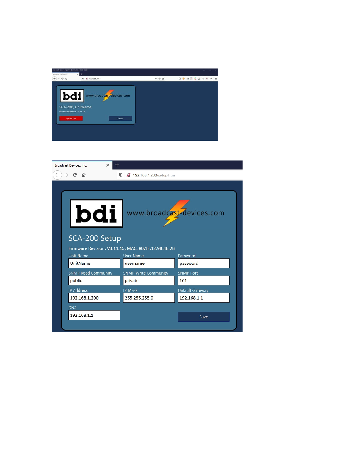
IV. Initial Operating Set up
After mounting the unit in the rack and applying power connect a CAT5 cable from a laptop
computer to the unit. The initial IP settings are as follows:
IP address: 192.168.1.200
Subnet mask: 255.255.255.0
Default Gateway: 192.168.1.1
Username: username Password: password

4
Once you enter the default IP address this screen should appear:
Press Setup and the IP setup page will appear:
Make changes and hit save but make sure you record the settings before exiting this screen. It is
a good idea to take as screen shot or record the username, password and IP address information
here:
Username: __________________________________________________
Password: ___________________________________________________
IP address: __________________________________________________
SNMP Port:__________________________________________________

5
In order for the setting to take effect the unit must be power cycled for at least 5 seconds.
Once the unit is confirmed on the desired IP address load the SCA APP supplied on the
accompanying CD ROM onto a computer. Once installed you can start the app by clicking on the
EXE file. Send it your desktop for convenience.
Once the APP starts you will see the following screen:
It is possible to have up to 5 SCA generators collocated or at other sites under management from
the same APP. You can give each unit a name by entering it in the space allowed.
Click OPEN on the desired generator presumably Unit 1 if you are only setting up one generator
chassis. The screen below will appear:

6
You will need to click on the Connect tab in order to set the IP address set up previously on the
browser interface screen.
Enter the IP address and port assignment if other than what is shown. Make certain that the port
is forwarded on the router that the unit is connected to or you will not be able to access the unit
from an outside connection. Make the changes and click on CONNECT.
You can go back to the Control screen and finish the setup. It is advisable to monitor the output of
the generator with a means of looking at the base band spectrum or a suitable SCA monitor while
performing these adjustments.
1. Select input
2. Set input gain. The unit is setup for 0 dBm with the adjustment at “0” default. A coarse
gain change in one dB increments and a fine adjust of 0.1 dB increments can be made by
using the UP/DOWN arrows. It is advisable to feed an audio signal in that is processed
with at least some form of peak limiter to limit modulation of the generator. The SCA-200
does no dynamic processing of the audio feeding it. This must be done ahead of the unit.
3. Set pre emphasis as desired. Off, 50, 75, 150 or 225uS
4. An optional audio low pass filter setting can be made to Off, 5 or 10 KHz
5. Mode select to On, Off or Auto. Auto places the unit in a mode whereby a lack of audio
signal at nominal level will mute the generator output after 10 seconds.
6. Set output gain which is the injection level for the exciter that the unit will feed. Again a
+/- 10 dB in 1 dB increments and fine adjust in 0.1 dB increments can be performed.

7
Remote Control – Parallel/GPIO DB25F Connection Table 2.
Command input pins require a momentary closure to common. Status connections open collector
outputs which require a 5 VDC pull up which is provided on pin 12.
SCA GEN 1 INPUT A SEL COMMAND
+5 VDC
CMD/STAT COM
SCA GEN 2 INPUT A SEL COMMAND
SCA GEN 2 OFF STATUS
CMD/STAT COM
SCA GEN 1 OFF STATUS
SCA GEN 2 ON STATUS
SCA GEN 1 B INPUT SELECTED STATUS
SCA GEN 1 ON COMMAND
CMD/STAT COM
SCA GEN 1 A INPUT SELECTED STATUS
SCA GEN 1 INPUT B SEL COMMAND
SCA GEN 2 B INPUT SELECTED STATUS
SCA GEN 1 ON STATUS
CMD/STAT COM
CMD/STAT COM
CMD/STAT COM
SCA GEN 2 A INPUT SELECTED STATUS
CMD/STAT COM
OPT SHIELD
SCA GEN 2 OFF COMMAND
SCA GEN 2 B INPUT SEL COMMAND
SCA GEN 1 OFF COMMAND
SCA GEN 2 ON COMMAND
CUST SUPPLIED
DB-25M
1
14
2
15
3
4
5
6
7
8
9
10
11
12
13
16
17
18
19
20
21
22
23
24
25

8
V. Specifications
Input: 2 – XLR balanced 600 Ohm – for each generator
Output: 2 – BNC 50 Ohm adjustable – for each generator
Sub Carrier Frequency: 67 KHz +/- 0.5% over environmental temperature range
Frequency Response: +/- 0.25 dB from 50 Hz to 10 KHz – 5 KHz low pass filter
switchable
Pre Emphasis: 50, 75, 150 or 225 uS switchable – each generator
Total Harmonic Distortion: Less than 0.5% over audio passband
Remote Control: Parallel GPIO, Ethernet SNMPv2, RS232/485 BDI Stack
Graphical User Interface supplied for setup and
operation
Power Requirements: 100-240VAC 50-60 Hertz @ 0.5 Ampere
Environmental: 0-50 degrees C. non condensing atmosphere
Mechanical: 19”W X 10”D X 1.75”H standard EIA rack enclosure
Shipping Weight/Dimensions 15 lbs, 22”W X 14”D X 7”H

9
FCC Certification Statement:
This device complies with Part 15 of the FCC Rules. Operation is subject to the
following two conditions: (1) this device may not cause harmful interference, and
(2) this device must accept any interference received, including interference that
may cause undesired operation.

1
VI. Warranty
Broadcast Devices, Inc. products are warranted against failure due to faultymaterials or workmanship
for a period of one year from the date of shi
pment from Broadcast Devices, Inc. dock. The warranty
covers repair or replacement of defective parts at the factory, provided the unit has been returned prepaid
by the user. All shipments to the factory shall have affixed to the outside of the container a
return
authorization number obtained from the factory. The above warranty is void if the unit has been modified
by the user outside of any recommendations from the factory or if the unit has been abused or operated
outside of its electrical or environment
al specifications. If customer conducted field tests suggest that the
unit may be faulty, whether or not the unit is in warranty, a full report of the difficulty should be sent to
Broadcast Devices, Inc. factory. The factory may suggest further tests or au
thorize return for factory
evaluation. Please email:
customer.service@broadcast-devices.com
Units sent to the factory should be well packed and shipped to Broadcast Devices, Inc. – Check
www.broadcast
-devices.com for current shipping address. Remember to affix the R.A. number to the
outside of the carton. Any packages received without such R.A. number will be refused. Note: freight
collect s
hipments will also be refused. When the unit has been received, inspected and tested, the
customer will receive a report of the findings along with a quotation for recommended repairs, which are
found falling outside of the standard warranty. Units returne
d for in-
warranty repairs, which are found not
to be defective will be subject to an evaluation and handling charge. In
-
warranty units will be repaired at
no charge and returned via prepaid freight.
Out-of-warranty units needing repair require a purc
hase order and will be invoiced for parts, labor, and
shipping charges.
When ordering replacement part, always specify A) Part Description, and Quantity; B) Date of
Purchase, Where Purchased; C) Any Special Shipping Instructions. Always specify a stre
et address, as
shipping companies cannot deliver to a postal box.
Broadcast Devices, Inc. is not responsible for any other manufacturer’s warranty on original
equipment. Nor are we responsible for any failure, damage, or loss of property that may occur
due to
the installation or operation of our equipment outside of recommended specifications.
Broadcast Devices, Inc. reserves the right to change materials, specifications, and features from
time to time.
www.broadcast-devices.com
Tel. (914) 737
-5032 Facsimile: (914) 736-6916
Email:
Customer.service@broadcast-devices.com
Table of contents
Other Broadcast Devices Portable Generator manuals
Popular Portable Generator manuals by other brands

PowerGrip
PowerGrip YG-2 Operation manual

Generac Power Systems
Generac Power Systems G1000M owner's manual

Togo POWER
Togo POWER GG3600 owner's manual

Champion Global Power Equipment
Champion Global Power Equipment 200962 quick start guide

Elektro-Automatik
Elektro-Automatik EL 3000A Series instruction manual

Claind
Claind NitroAir user manual

Tabor Electronics
Tabor Electronics WW2572A How to Simply Generate a PSK Modulation

Eberg
Eberg OMI user manual

Generac Power Systems
Generac Power Systems Mobile Power MMG205 Specifications

SIGLENT
SIGLENT SDG800 Series Service manual

Powermate
Powermate PC0495503 instruction manual

Westinghouse
Westinghouse iGen2200 instruction manual