Broadcast Devices AES-200 Product manual

Broadcast Devices, Inc.
Technical Reference Manual
AES-200 Digital Audio Switcher/DA
Broadcast Devices, Inc.
5 Crestview Avenue
Cortlandt Manor, NY 10567
Tel. (914) 737-5032
Fax. (914) 736-6916
Rev B. 10/97

Table of Contents
I. Unpacking and Inspection
Introduction
Basic Description and Operation
Installation ...................................................................................................................... 1
Remote Control Connection ........................................................................................... 2
II. Specifications ................................................................................................................3
III. Schematic Diagrams
AES-200 Simplified Block Diagram .............................................................................. 4
Digital Distribution Amplifier Board ......... ..................................................................... 5
CDR-200 Digital Switching Input Board ....................................................................... 6
BPS-300 Power Supply Board ..................................................................................... 7
IV. Warranty .................................................. ....................................................................8

I. UNPACKING AND INSPECTION
Carefully unpack the unit after receipt and inspect for any possible damage caused in shipping. If
damage is noted, contact shipper immediately and file a damage claim. The contents of the
package have been insured to cover total replacement cost. Make certain that the package
contents are the same as noted on the packing slip. If not, contact Broadcast Devices, Inc.
Check to see that all mechanical parts are secure.
INTRODUCTION
The AES-200 Digital Distribution Amplifier/Switcher is intended to be used in conjunction with
suitable AES/EBU signal sources in order to switch between two such sources and distribute
them two ways. The typical configuration would be to accept two digital sources main/alt STL, or
main/alt processing gear and distribute them to a main/alt. transmitter configuration. A third
output is available for test . A jack is provided at the front of the unit for use with an oscilloscope
or voltmeter. A fourth unbalanced, B.N.C. output is available at the rear panel for coaxial feeds.
BASIC DESCRIPTION OF OPERATION
Switching between the "1" and "2" inputs is accomplished at the front panel via push-button
switches or via a momentary ground applied to the appropriate remote control pins at the rear of
the unit. Front panel status is provided by LEDs and by dry relay contacts for remote indication.
The "1" and "2" inputs to the digital switcher/DA are balanced with a 110 ohm input
impedance. All DA outputs are factory configured to provide a 110 ohm output. All digital
connections to the unit are made via XLR connectors or B.NC. and the remote /status
connections are made via a "D" type connector at the rear of the unit.
INSTALLATION
Locate the AES -200 in a 19" EIA standard rack in close proximity to the equipment that will
be connected to it. Allow sufficient air space between equipment to allow for proper cooling. It is
important that the cables fed from digital sources such as processors and STLs to the AES-200
be kept short as most of this type of equipment is not designed to feed long capacitive lines. The
AES-200 itself can drive up to 25 foot cables with no degradation of the signal. It is advisable
however to keep output cable from the AES-200 as short as is practical.
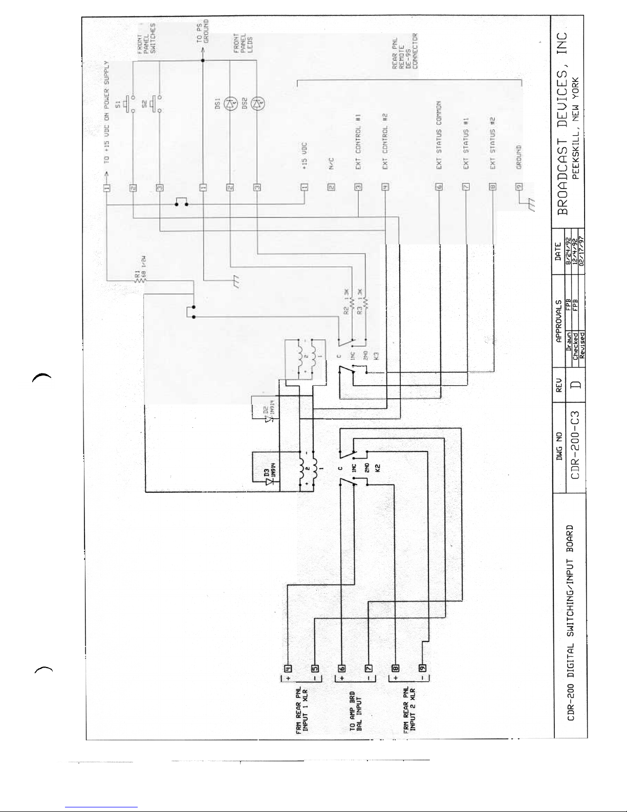
To connect a remote control to the AES-200, refer to the remote control connector diagram
included in this technical manual. Simple momentary closure to ground is all that is necessary to
command the AES-200 from one input to another. Status can be connected via the dry contacts
provided. The status contacts are rated at 24 VDC/2 amps. Do not attempt to use 110 VAC for
status indication. The contacts of the status relay are not sufficiently rated and the signals will be
subjected to a 60 hertz hum field.

REMOTE CONTROL
The AES-200 is fully remote controllable via a rear panel 9 pin DE connector. In addition to
remote control of the channel switching function, channel status is available. The control pins (3
and 4) are ground start and require only a momentary connection to ground for actuation. The
status pins (7 and 8) are dry isolated contacts that provide a closure to status common pin
number (6) that can be user configurable for either voltage or ground status. The status contacts
are rated at 24 VDC/2 amperes. Do not attempt to use 110 VAC for status indications without the
use of an external relay. Refer to table 1 below for complete pin out information for the rear
panel D connector.
TABLE 1 : Remote Control Pinout
PIN # FUNCTION
1 +15 VDC (200 mA MAX.)
2 NC
3 Control #1 Input
4 Control #2 Input
5 NC
6 Status Common
7 Status Channel #1 “ON”
8 Status Channel #2 “ON”
9 Ground

II. SPECIFICATIONS
Number of Inputs 2 - Balanced
Number of Outputs 2 - Balanced AES/EBU Standard, 2 - Unbalanced
B.N.C.
Input Connectors 2 - XLR - Female - AES/EBU Standard
Output Connectors 2 - XLR - Male - AES/EBU Standard 2 - Unbal. B.N.C.
Input/Output Impedance 110 Ohms Balanced 55 ohms for unbalanced
outputs
Remote Control Ground Start
Remote Connector 9 Pin D Type
Status Dry Contact NO/NC/COM Remote, Front Panel LED’s
Power Requirements 100/120/220/240VAC 50 - 60 Hz @ 0.5A. Maximum
Power Receptacle E.I.A. Standard 3 Wire Grounded
EMI Protected Power Entry
Physical Dimensions 19” W X 1.75” H X 11.5” D E.I.A. Standard Rack
Operating Environment 0 - 60 Degree Celsius

III. SCHEMATIC DIAGRAMS


IV. WARRANTY
Broadcast Devices, Inc. products are warranted against failure due to faulty workmanship or
materials for a period of one year from date of shipment to the customer. The warranty covers
repair or replacement of defective parts at the factory, provided the unit has been returned by the
customer , via prepaid freight under a return authorization obtained from the factory. The return
authorization number shall be affixed to the outside of the shipping container. Parcels not bearing
a return authorization number are subject to refusal.
The above warranty is void if the unit in question has been modified in any way or has been
abused or operated outside of its electrical and environmental specifications.
If customer conducted field tests suggest that the unit is defective and should be returned for
evaluation, a full written report of the difficulty should accompany the unit.
Units returned for evaluation should be packed carefully and shipped via prepaid freight. Make
sure that the return authorization number appears on the outside of the carton. Freight collect
shipments will be refused. When a unit has been received, inspected and tested the customer
will receive a report of the trouble along with a quotation on any recommended repairs falling
outside of the warranty.
Units returned for repair under warranty found not to be defective will be subject to a $25.00
inspection charge plus return freight charges. In warranty units found to be defective will be
repaired and returned at no cost to the customer. In addition, a credit will be issued for incoming
freight charges.
Out of warranty units needing repair require a purchase order and will be invoiced for parts,
labor, and return freight charges.
When ordering parts, always specify:
A) Part description and quantity
B) Method of shipment and any special shipping instructions
Parts and service inquires may be directed to:
Broadcast Devices, Inc.
5 Crestview Avenue
Cortlandt Manor, NY 10567
Tel: (914) 737-5032
Fax: (914) 736-6916
Email: [email protected]
Table of contents
Other Broadcast Devices Switch manuals