PTN MDV Series User manual

PTN Electronics
DVI Matrix Switchers System
User Manual
MD
V
Series --- DVI/Audio Matrix Switche
r

DVI/AudioMatrixSwitcher
PTN Electronics Limited www.PTN-electronics.com
ii
Please read this manual carefully before using this product.
Notes:
This DVI Matrix Switchers User Manual takes example of the Matrix model
MDV88A Pro. It can be used as user’s manual of other MDV matrix switcher
models.
This manual is only an instruction for operators, not for any maintenance usage.
The functions described in this version are updated till Sep 2010. Any changes of
functions and parameters since then will be informed separately. Please refer to
the dealers for the latest details.
This manual is copyright PTN Electronics Limited. All rights reserved. No part of
this publication may be copied or reproduced without the prior written consent of
PTN Electronics Limited.
All product function is valid till 2010-9-1

DVI/AudioMatrixSwitcher
PTN Electronics Limited www.PTN-electronics.com
iii
!
Safet
y
O
p
eration Guide
In order to guarantee the reliable operation of the equipments and safety of the staff,please
abide by the following proceeding in installation, using and maintenance:
⑴
The system must be earthed properly. Please do not use two blades plugs and ensure the alternating
power supply ranged from 100v to 240v and from 50Hz to 60Hz.
⑵
Do not put the switcher in a place where is too hot or too cold.
⑶
As the power generating heat when running, the working environment should be maintained
fine ventilation, in case of damage caused by overheat.
⑷
Please cut off the general power switch in humid weather or left unused for long time.
⑸
Before following operation, ensure that the alternating current wire is pull out of the power
supply:
A.Take off or reship any components of the equipment.
B.Take off or rejoin any pin or other link of the equipment.
⑹
As to non-professional or without permission, please DO NOT try to open the casing of the
equipment, DO NOT repair it on your own, in case of accident or increasing the damage of the
equipment.
⑺
DO NOT splash any chemistry substance or liquid in the equipment or around.

DVI/AudioMatrixSwitcher
PTN Electronics Limited www.PTN-electronics.com
iv
Contents
1.Introduction............................................................................................................................. 1
1.1About DVI Matrix Switcher System .............................................................................................1
1.2DVI Matrix Switcher Models.........................................................................................................1
2.MDV Packing of the Product............................................................................................... 2
3.MDV Installation...................................................................................................................... 3
4.Front View and Rear View of the Product........................................................................ 3
4.1Front view of MDV88A Pro ...........................................................................................................3
4.2Rear view of MDV88A Pro.............................................................................................................4
5.External Connection.............................................................................................................. 4
5.1Introduction of the Input and Output Connectors ......................................................................4
5.2Connection of RS-232 Communication Port................................................................................4
5.2.1Connection with Control System .........................................................................................................4
5.2.2Connection with Computer...................................................................................................................4
5.3How to Connect with the Input and Output Terminals...............................................................5
6.Operation of the EDID management................................................................................. 7
6.1 EDID automatically shake hand .........................................................................................................7
6.2 EDID management by RS232 commands .......................................................................................8
6.3 EDID management by buttons.........................................................................................................9
7. Operation of the Control Panel........................................................................................ 10
7.1 Front Panel Description.....................................................................................................................10
7.2 Command Format of the Switching Operation...............................................................................11
7.3 Examples of Operation.......................................................................................................................11
8. Usage of the Remote Controller......................................................................................... 12
9.Communication Protocol and Command Codes......................................................... 13
11.Troubleshooting & Maintenance ....................................................................................... 17

DVI/AudioMatrixSwitcher
PTN Electronics Limited www.PTN-electronics.com
1
1.Introduction
1.1 About DVI Matrix Switcher System
MDV series Matrix switcher is a high-performance professional computer and audio signal
switcher that can be used for cross switching of multi computer and audio signal. Independent
DVI component and balance/unbalance I/O terminals make each component signal transmit and
switch separately; this design can reduce attenuation of signal transmission to minimum and
output the image and audio signal in high-fidelity quality.
DVI series switcher mostly apply in broadcasting TV engineering, multi-media meeting room, big
screen display engineering, television education, command control center or other fields. A/V
timing or separating switching function. It also has an adaptable compensation to extend the input
distance to 36 meters. With RS232 interface, it can be worked with PC, remote control system
and any other far-end control system devices. The user manual takes MDV88Apro as example,
other models can take reference from it too.
1-1 DVI88A Pro switcher
1.2 DVI Matrix Switcher Models
According to different situation and users, the DVI series can be classified into the following models:
Specification
Model Video Inputs Video Outputs Audio Inputs Audio Outputs RS232
MDV44APro 4 4 4 4
√
MDV88APro 8 8 8 8
√
MDV1616APro 16 16 16 16
√
MDV3232APro 32 32 32 32
√
MDV6464APro 64 64 64 64
√
MDV9696APro 96 96 96 96
√
MDV128128APro 128 128 128 128 √
MDV144144APro 144 144 144 144 √

DVI/AudioMatrixSwitcher
PTN Electronics Limited www.PTN-electronics.com
2
Specification
Model Video Inputs Video Outputs Audio Inputs Audio Outputs RS232
MDV44Pro 4 4 x x √
MDV88Pro 8 8 x x √
MDV1616Pro 16 16 x x √
MDV3232Pro 32 32 x x √
MDV6464Pro 64 64 x x √
MDV9696Pro 96 96 x x √
MDV128128Pro 128 128 x x √
MDV144144Pro 144 144 x x √
2. MDV Packing of the Product
DVIMatrix Switcher
IRremote
RS-232 Communication Cord
Power Supply Cord
CD
User Manual and Quality Guarantee

DVI/AudioMatrixSwitcher
PTN Electronics Limited www.PTN-electronics.com
3
3. MDV Installation
DVI matrix switchers adopt metal shell and can be stacked with other device. Moreover, they are
rack-mountable enclosure and can be installed in the standard 19 inches case.
4. Front View and Rear View of the Product
4.1 Front view of MDV88A Pro

DVI/AudioMatrixSwitcher
PTN Electronics Limited www.PTN-electronics.com
4
4.2 Rear view of MDV88A Pro
5. External Connection
5.1 Introduction of the Input and Output Connectors
According to different type of matrix, computer signal I/O interface are made up of 8-channel
BNC ports and DVI-D female ports respectively. audio signal I/O terminals are make
up of 8-channel BNC ports and Captive screw connectors ports respectively. Please refer to
shell silk-screen figure about other types of interface.
5.2 Connection of RS-232 Communication Port
Besides the front control panel, the DVI matrix switcher can be controlled by far-end control
system or through the Ethernet control via the RS-232 communication port.
5.2.1 Connection with Control System
With the RS-232 port, the DVI matrix switchers can be controlled by several kinds of control
systems.
This RS-232 communication port is a female 9-pin D connector. The
definition of its pins is as the table below.
No. Pin Function
1 N/u Unused
2 Tx Transmit
3 Rx Receive
4 N/u Unused
5 Gnd Ground
6 N/u Unused
7 N/u Unused
8 N/u Unused
9 N/u Unused
F 5-1 9HDF
5.2.2 Connection with Computer
When the switcher connects to the COM1 or COM2 of the computer with control software, users

DVI/AudioMatrixSwitcher
PTN Electronics Limited www.PTN-electronics.com
5
can control it by that computer.
To control the switcher, users may use the public COM software. Please refer the details in
Communication Protocol and Command Codes
F 5-2 MDV connecting to computer
5.3 How to Connect with the Input and Output Terminals
The DVI matrix switchers may take DVD players, computers, graphic workstations and digital
showing platform as their input signal source, and projectors, video recorders, displayers and
amplifiers as their output signal destinations according to different situation.
DVI-I Dual Link:
F5—3 DVI-I Dual Link port
DVI-D pin function
PIN function PIN function
1 T.M.D.S.Data2- 13 T.M.D.S.Data3+
2 T.M.D.S.Data2+ 14 +5V Power
3 T.M.D.S. Data 2/4 Shield 15 Ground (for +5V)
4 T.M.D.S. Data 4- 16 Hot Plug Detect
5 T.M.D.S. Data 4+ 17 T.M.D.S. Data 0-
6 DDC Clock 18 T.M.D.S. Data 0+
7 DDC Data 19 T.M.D.S. Data 0/5 Shield

DVI/AudioMatrixSwitcher
PTN Electronics Limited www.PTN-electronics.com
6
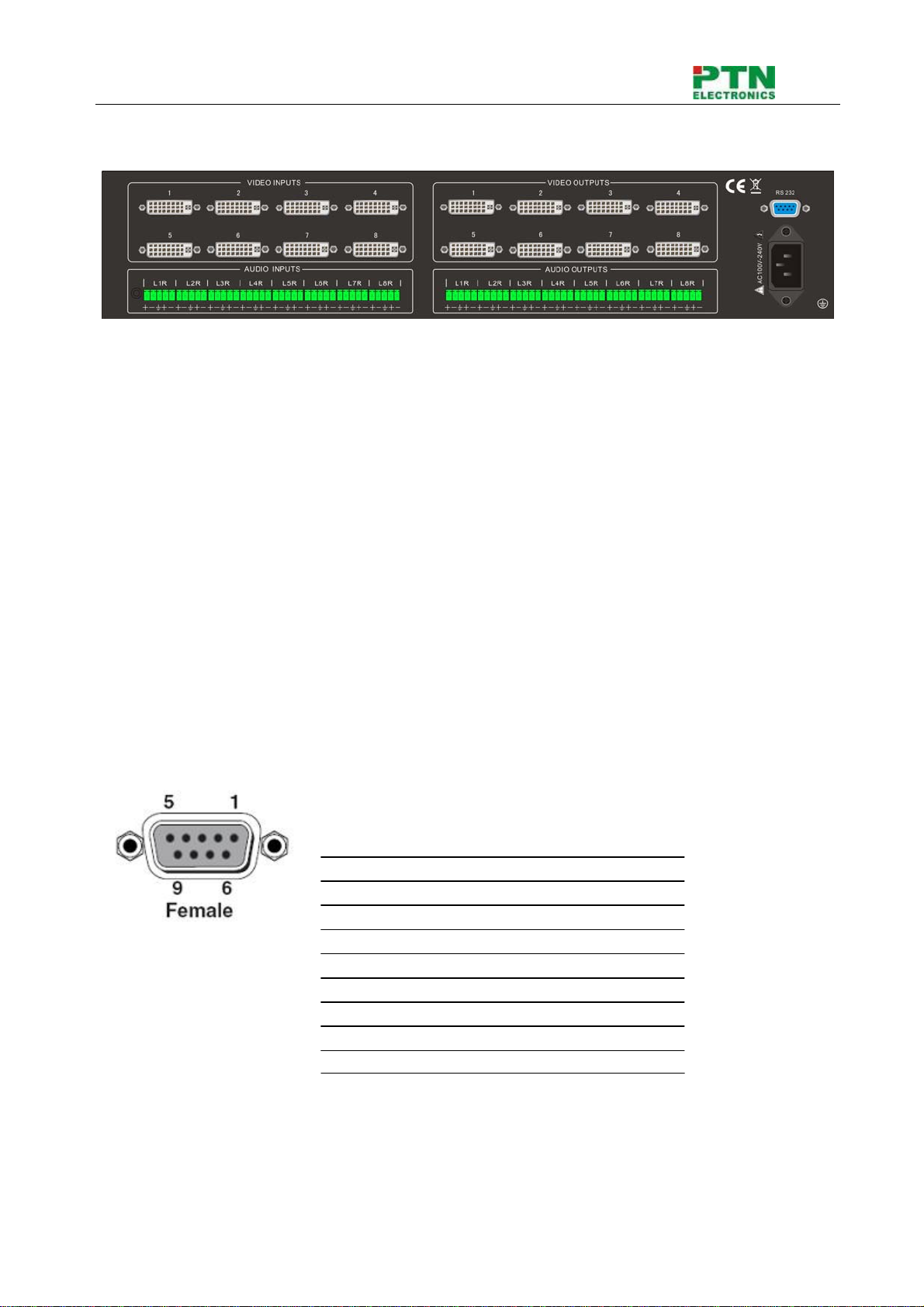
8 No Connect 20 T.M.D.S.Data5-
9 T.M.D.S.Data1-21 T.M.D.S.Data5+
10 T.M.D.S.Data1+ 22 T.M.D.S. Clock Shield
11 T.M.D.S.Data1/3 Shield 23 T.M.D. S. Clock +
12 T.M.D.S.Data3-24 T.M.D.S .Clock-
Audio signal connection:
“AUDIO INPUT”, “AUDIO OUTPUTS” audio network interface in DVI matrix switchers (MDV) can be
connected to the audio signal and amplify of the DVD player.
Audio connection is little complicated than video. It has two kinds of connection: balanced and
unbalanced.
The balanced connection transmits a pair of balanced signals with two signal cords. Because
interferences will have the same intensity and the opposite phases on the two signal cords, it will be
counteracted in the end. For the low frequency extent of the audio signal, it would be easily interfered
under long distance transmission. Therefore, as an anti-interference connection, it is mostly used in
audio connection of special device.
The unbalanced connection transmits signals only with a signal cord. Without counteraction, it can be
interfered more easily. Accordingly, it is adopted for household appliance or some cases with low
technical demand.
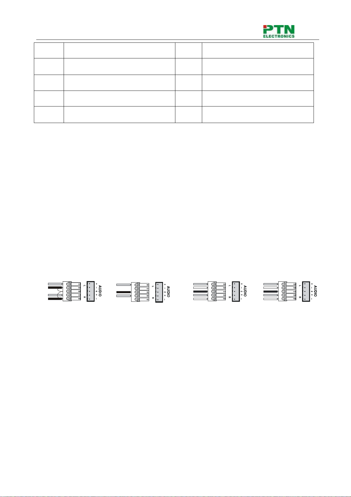
Take the audio signal line for example: 1.Unbalanced: pin “G” connect to SLEEVE, pin “+” connect to
TIP, pin “–” connect to pin “G”; 2.Balanced: pin “G” connect to SLEEVE, pin “–” connect to RING, pin “+”
connect to TIP. As shown in the F 5-3:
Unbalanced Input
Tip
Tip
Sleeve
Balanced Input
Tip
Ring
Tip
Ring
Unbalanced Output
Tip
Tip
Sleeve
Sleeves Sleeves
Balanced Output
Tip
Ring
Tip
Ring
Sleeves
F5-3 5 bit 3.8mm Balanced/unbalanced connection on captive screw connector. To select which
connection is up to the interface of the device. When available, the balanced connection is the first
choice. Before connection, please read the command or relevant demand in the user manual carefully.
In some cases, maybe there is balanced in source signal end but unbalanced in the destination end. If
in a nonstandard case, it is done to connect balanced for the balanced end and unbalanced for
unbalanced end. But if in a standard one, the converter must be used to switch the signals as the same,
balanced or unbalanced.

DVI/AudioMatrixSwitcher
PTN Electronics Limited www.PTN-electronics.com
7
System Diagram:
F5-4 DVI matrix system connection
6. Operation of the EDID management
MDV matrix switcher is built in the EDID management database. The EDID management can be
automatically shake hand, or manual exchanged, and factory restore.
6.1 EDID automatically shake hand
The MDV matrix switcher is built in the EDID data, which can communicate with the displayers and
video source automatically. When the displayers or video sources are connected to the MDV matrix
switcher, they will share the EDID/DDC information with the matrix switcher.

DVI/AudioMatrixSwitcher
PTN Electronics Limited www.PTN-electronics.com
8
We take a MDV88A as example. The communication solution is like this:
The MDV EDID database includes most popular displaying data, but not all the displaying data because
of the capability and firmware limitation. So, we can manually refresh the EDID data to update the EDID
data base.
EDID hand-shake priority
The EDID refresh ports have the priority grade, ranging from output 1 to output 8 in priority order. It
means the output 1 is the most prior to exchange the EDID data, and then the output 2 is the second
prior to exchange the EDID data. And, the output 8 is the least prior.
When the user carry the EDID erase/refresh function, the MDV will detect the output priority and
exchange the EDID data with the available most prior output port.
6.2 EDID management by RS232 commands
When you need to refresh the EDID data of MDV matrix switcher, we can manually exchange the EDID
data by sending the RS232 command “EDIDMOn.” (Please notice the text-transform, and the dot in
behind.)

DVI/AudioMatrixSwitcher
PTN Electronics Limited www.PTN-electronics.com
9
Erase and Refresh the EDID data
When the “EDIDMOn.” is sent, the MDV matrix switcher will copy the EDID data from the most prior
output port. It means the MDV will erase the old EDID data, and fully copy the EDID data from the
displayer which is connected to the most prior output port.
EDID restore to factory default
When we send the “EDIDMInit.” to the MDV matrix switcher, it will recover the factory default EDID
data.
RS232 feedback:
When the “EDIDMOn.” or “EDIDMInit.” is correctly sent, all the connected displayers will be blank for
2~3 seconds and recover again. And, the MDV matrix switcher will send out a RS232 feedback
command “EDIDMOn.” or “EDIDMInit.”.
If all these symbols works, it means the action is taken
6.3 EDID management by buttons
When you need to recover the ex-factory default EDID data set, we can send the RS232 command or
press the buttons of the front panel/IR remote to make it work.
Erase and Refresh the EDID data
Keep pressing the button “<-” for 30 secnds , all the LED of “<-” will be on for 10 seconds. It enters the
EDID setting status.
And, pressing “Input 2” button and “Undo” button. All the outputs will be blank for 3 seconds, to carry the
“EDIDMOn.” command, to refresh the EDID.

DVI/AudioMatrixSwitcher
PTN Electronics Limited www.PTN-electronics.com
10
EDID restore to factory default
Keep pressing the button “<-” for 30 secnds , all the LED of “<-” will be on for 10 seconds. It enters the
EDID setting status.
And, pressing “Input 1” button and “Undo” button. All the outputs will be blank for 3 seconds, to carry the
“EDIDInit.” command, to restore the EDID to factory default.
7. Operation of the Control Panel
7.1 Front Panel Description
“AV” AV synchronal button: To transfer video and audio signal synchronously by the switcher
Example: To transfer both the video and the audio signals from input channel No.3 to
output channel No.4.
Operation: Press buttons in this order “AV”,“3”,, “4””.
“VIDEO” Video button: To transfer only video signals from input channel to output channel
Example: To transfer video signals from input channel No.3 to output channel No.4.
Operation: Press buttons in this order “VIDEO”, “3”, “4”.
“AUDIO” Audio button: To transfer only audio signals from input channel to output channel
Example: To transfer audio signals from input channel No.2 to output channel No.3.
Operation: Press buttons in this order ““AUDIO”, “2”, “3””.
“1,2,3,4” I/O Keypads: Keys to select I/O channels.
Example: To transfer input channel No.3 to output channel No.1
Operation: Press buttons in this order : “3” in INPUT area, “1” in OUTPUT area.
“All ” The button to transfer one input channel to all output channels
Example :To transfer input1 to all outputs.
Operation: Press buttons in this order : “1”, “All”.

DVI/AudioMatrixSwitcher
PTN Electronics Limited www.PTN-electronics.com
11
“Though” The button to transfer input to the corresponding output.
Example :To transfer input 2 to output 2
Operation :Press the button in this order : “2”, “Though”
“ ←” Backspace button: To backspace the latest input button
Example:Tocancelinput3
Operation:Pressbuttoninthisorder:“3”,“ ←”
“UNDO” Undo button: To resume to the status before the command just performed
Example: To cancel you latest switching status :input 3 through output 5
Operation: Press the button in this order: “3” input area, “5” output area, “UNDO”
7.2 Command Format of the Switching Operation
With the front control panel, the switcher could be control directly and rapidly by pressing the buttons
under below format.
“Menu” +“Input Channel” +“Output Channel 1”
“Menu”: “AV”, “Audio”, “Video”
“Input Channel”: Fill with the number of input channel to be controlled
“Output Channel”: Fill with the number of output channels to be controlled
7.3 Examples of Operation
Example 1:To transfer video and audio signals from input channel No.1 to output channel
No.3,4
1, Press the button for switching mode “AV” for the switching mode of video
and audio (“Audio” for the switching mode of audio only; “Video” for the
switching mode of video only)
2, Press the button for input channel number“1”
3,Press the button for the first output channel number “3”
”
4, Press the button for the second output channel number “4”
Then, switching OK ! audio/video switching from “1” to “3” and “4”
AV AudioVideo
342
342
1342

DVI/AudioMatrixSwitcher
PTN Electronics Limited www.PTN-electronics.com
12
8. Usage of the Remote Controller
With the infrared remote controller, the matrix switcher could be control remotely. Because the function
buttons on the remote controller are the same with the ones on the front control panel, the remote
controller shares the same control operation and command format with the control panel.
The inputs
channels, from
0~9, and
plusing “10+”
for more
Menu, for
switching
source and
function
The outputs
channels, from
0~9, and
plusing “10+”
for more

DVI/AudioMatrixSwitcher
PTN Electronics Limited www.PTN-electronics.com
13
9.Communication Protocol and Command Codes
With this command system, the RS232 software is able to control and operate the DVI Matrix with
remotely.
Communication protocol:
Baud rate: 9600 Data bit: 8 Stop bit: 1 Parity bit: none
Command
Types
Command
Codes
Functions
System Command
/*Type; Inquire the models information.
/%Lock; Lock the keyboard of the control panel on the Matrix.
/%Unlock; Unlock the keyboard of the control panel on the Matrix.
/^Version; Inquire the version of firmware
/:MessageOff; Turn off the feedback command from the com port. It will only show
the “switcher OK”.
/:MessageOn; Turn on the feedback command from the com port.
EDIDMOn. Manually adjust the EDID with the most priority output port.
EDIDMInit. Recover the factory default EDID data
Undo. To cancel the previous operation.
Demo. Switch to the “demo” mode, 1->1, 2->2, 3->3 … and so on.
[x1]All. Transfer signals from the input channel [x1] to all output channels
All#. Transfer all input signals to the corresponding output channels
respectively.
All$. Switch off all the output channels.
[x1]#. Transfer signals from the input channel [x1] to the output channel
[x1].
[x1]$. Switch off the output channel [x1].
Operation Command (PTN2.0 Command System)
[x1] V[x2]. Transfer the video signals from the input channel [x1] to the output
channel [x2].
[x1]
V[x2],[x3],[x4].
Transfer the video signals from the input channel [x1] to the output
channels [x2], [x3] and [x4].
[x1] A[x2]. Transfer the audio signals from the input channel [x1] to the output
channel [x2].
[x1]
A[x2],[x3],[x4].
Transfer the audio signals from the input channel [x1] to the output
channels [x2], [x3] and [x4].
[x1] B[x2]. Transfer both the video and the audio signals from the input channel
[x1] to the output channel [x2].
[x1]
B[x2],[x3],[x4].
Transfer both the video and the audio signals from the input channel
[x1] to the output channels [x2], [x3] and [x4].
Status[x1]. Inquire the input channel to the output channel [x1].
Status. Inquire the input channel to the output channels one by one.
Save[Y]. Save the present operation to the preset command [Y]. [Y] ranges
from 0 to 9.

DVI/AudioMatrixSwitcher
PTN Electronics Limited www.PTN-electronics.com
14
Recall[Y]. Recall the preset command [Y].
Clear[Y]. Clear the preset command [Y].
Note:
1. [x1], [x2], [x3] and [x4] are the symbols of input or output channels ranged according to the
model of the matrix switcher. If the symbols exceed the effective range, it would be taken as a
wrong command.
2. In above commands, “[”and “]” are symbols for easy reading and do not need to be typed in
actual operation.
3. Please remember to end the commands with the ending symbols “.” and “;”.
Detail Examples:
1、Transfer signals from an input channel to all output channels: [x1]All.
Example: To transfer signals from the input channel No.3 to all output channels. Run Command:
“3All.”
2、Transfer all input signals to the corresponding output channels respectively: All#.
Example: If this command is carried out on an MVG1616-A matrix switcher, the status of it will be:
1->1, 2->2, 3->3, 4->4……16->16.
3、Switch off all the output channels: All$.
Example: After running this command, there will be no signals on all the output channels.
4、Check the version of the firmware: /^Version;
To check the version of the firmware.
5、Switch off the detail feedback command from the COM port: /:MessageOff;
Switch off the detail feedback information from the COM port. But, it will leave the “switch OK” as
the feedback, when you switch the matrix.
6、Switch on the detail feedback command from the COM port: /:MessageOn;
Switch on the detail feedback information from the COM port. it will show the detail switch
information when it switch. Example: when switch 1->2 for Audio, it will feedback “A0102”.
7、Transfer signals from an input channel to the corresponding output channel: [x]#.
Example: To transfer signals from the input channel No.5 to the output channel No.5. Run
Command: “5#.”
8、Switch off an output channel: [x]$.
Example: To switch off the output channel No.5. Run Command: “5$.”
9、Switch video signals command: [x1] V[x2].
Example: To transfer the video signals from the input channel No.3 to the output channel No.5.
Run Command: “3V5.”
10、Switch audio signals command: [x1] A[x2].
Example: To Transfer the audio signals from the input channel No.10 to the output channel
Run Command: “10A2.”
11、Switch both video and audio signals synchronously: [x1] B[x2].
Example: To transfer both the video and the audio signals from the input channel No.120 to the
output channel No.12,13,15. Run Command: “120B12,13,15.”
12、Inquire the input channel to the output channel [x]: Status[x].
Example: To inquire the input channel to the output channel No.23. Run Command: “Status23.”

DVI/AudioMatrixSwitcher
PTN Electronics Limited www.PTN-electronics.com
15
13、Inquire the input channel to the output channels one by one: Status.
Example: To inquire the input channel to the output channels one by one. Run Command:
“Status.”
14、Save the present operation to the preset command [Y]: Save[Y].
Example: To save the present operation to the preset command No.7. Run Command: “Save7.”
15、Recall the preset command [Y]: Recall[Y].
Example: To recall the preset command No.5. Run Command: “Recall5.”
16、Clear the preset command [Y]: Clear[Y].
Example: To clear the preset command No.5. Run Command: “Clear5.”

DVI/AudioMatrixSwitcher
PTN Electronics Limited www.PTN-electronics.com
16
10. Specification
Video Input Video Output
Input 8 DVI Output 8 DVI
Input Connector Female DB24+5 Output Connector Female DB24+5
Input Level T.M.D.S. 2.9V/3.3V Output Level T.M.D.S. 2.9V/3.3V
Input Impedence 75ΩOutput Impedence 75Ω
Video General
Gain 0 dB Bandwidth 340 MHz (10.2 Gbit/s)
Video Signal DVI 1.0 standard DVI-D full digital
T.M.D.S signal Max Time-delay 5nS (±1nS)
Switching Speed 200ns (Max.) Crosstalk <-50dB@5MHz
EDID and DDC
Management
Supports Extended Display Identification Data (EDID) and Display Data Channel (DDC) data
using DVI and HDMI standards, EDID and DDC signals are actively bufferred.The built-in
EDID/DDC database can analyze these two signals, mix them, and realize the handshake of
them internally.
HDCP Management
Compliant with High-bandwidth Digital Content Protection (HDCP) using DVI and HDMI 1.3
standards. The built-in HDCP management technology can analyze HDCP key, and realize the
handshake internally.
Audio Input Audio Output
Input 8 stereo, balanced/unbalanced Output 8 stereo, balanced/unbalanced
Input Connector Captive screw connectors, 5 pole Output Connector Captive screw connectors, 5 pole
Input Impedance >10KΩOutput Impedance 50Ω
Audio General
Frequency Response 20Hz ~ 20KHz CMRR >90dB@20Hz~20KHz
Stereo Channel
Separation >80dB@1KHz THD + Noise 1%@1KHz, 0.3%@20KHz at
nominal level
Control Parts
Serial Control Port RS-232, 9-pin female D connector Pin Configurations 2 = TX, 3 = RX, 5 = GND
IR Remote Default IR remote Front Panel Control Buttons
Options TCP/IP control by PTNET(PTN's programmable interface)
General
Power Supply 100VAC ~ 240VAC, 50/60Hz Power Consumption 25W
Temperature -20 ~ +70℃Humidity 10% ~ 90%
Case Dimension W483 x H87 x D320mm
(2U high, full rack wide) Product Weight 2.5Kg
This manual suits for next models
7
Table of contents
Other PTN Switch manuals