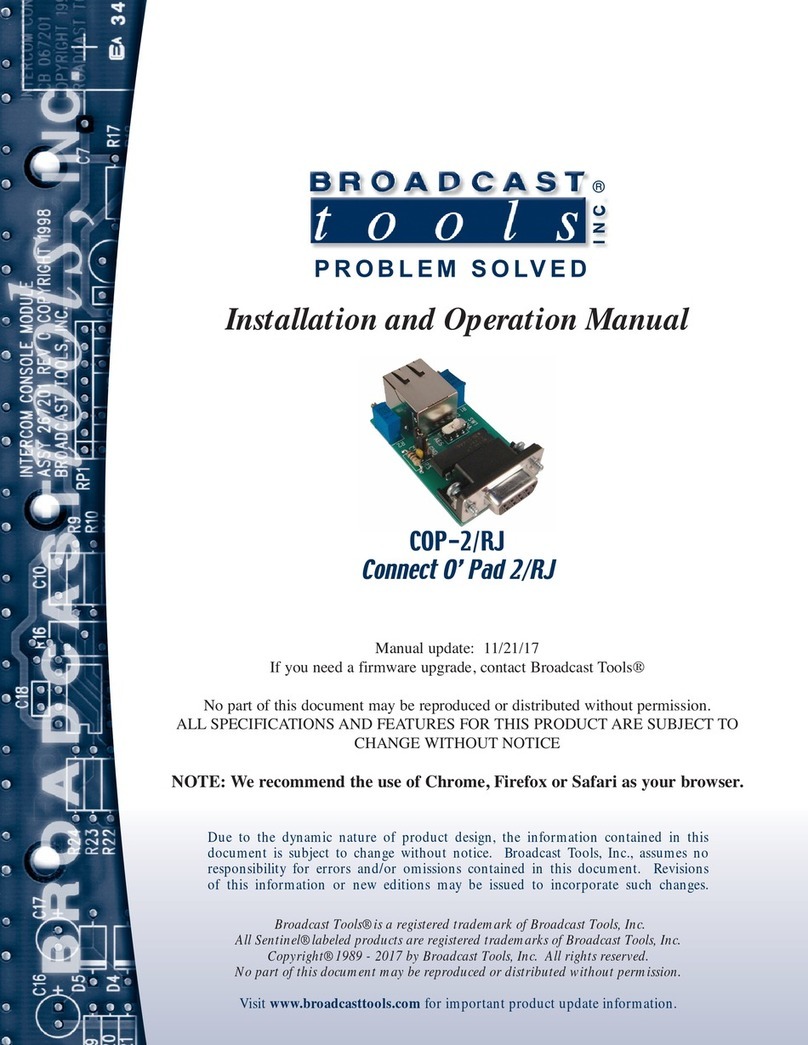
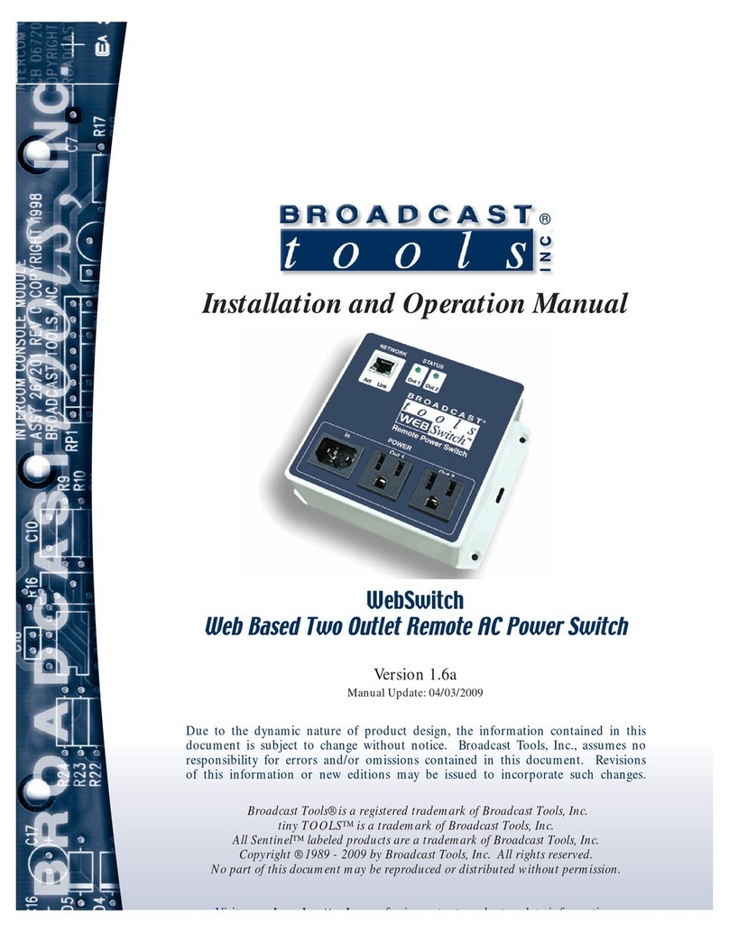
Broadcast Tools RJ-XLR Series User manual

Installation and Operation Manual
PROBLEM SOLVED
Due to the dynamic nature of product design, the information contained in this
document is subject to change without notice. Broadcast Tools, Inc., assumes no
responsibility for errors and/or omissions contained in this document. Revisions
of this information or new editions may be issued to incorporate such changes.
Broadcast Tools® is a registered trademark of Broadcast Tools, Inc.
All Sentinel® labeled products are registered trademarks of Broadcast Tools, Inc.
Copyright® 1989 - 2020 by Broadcast Tools, Inc. All rights reserved.
No part of this document may be reproduced or distributed without permission.
Visit www.broadcasttools.com for important product update information.
Manual update: 8/25/2020
If you need a firmware upgrade, contact Broadcast Tools®
No part of this document may be reproduced or distributed without permission.
ALL SPECIFICATIONS AND FEATURES FOR THIS PRODUCT ARE SUBJECT TO
CHANGE WITHOUT NOTICE
NOTE: We recommend the use of Chrome, Firefox or Safari as your browser.
RJ-XLR Breakout Panels
RJ-XLR 8F 8M (8 Female XLR, 8 Male XLR)
RJ-XLR 16F (16 Female XLR)
RJ-XLR 16M (16 Male XLR)
INC
®

RJ-XLR Installation and Operation Manual
Table of Contents
Section Title . . . . . . . . . . . . . . . . . . . . . . . . . . . . . . . . . . Page #
Introduction . . . . . . . . . . . . . . . . . . . . . . . . . . . . . . . . . . . . . . . . . . . . . 3
Safety Information . . . . . . . . . . . . . . . . . . . . . . . . . . . . . . . . . . . . . . . . 3
Who to Contact for Help . . . . . . . . . . . . . . . . . . . . . . . . . . . . . . . . . . . 3
Product Overview . . . . . . . . . . . . . . . . . . . . . . . . . . . . . . . . . . . . . . . . 4
Inspection . . . . . . . . . . . . . . . . . . . . . . . . . . . . . . . . . . . . . . . . . . . . . . . 4
Installation/Operation. . . . . . . . . . . . . . . . . . . . . . . . . . . . . . . . . . . . . . 5
Physical Properties . . . . . . . . . . . . . . . . . . . . . . . . . . . . . . . . . . . . . 5
Chassis Ground Screw . . . . . . . . . . . . . . . . . . . . . . . . . . . . . . . . . . 5
Ground Lift Jumper . . . . . . . . . . . . . . . . . . . . . . . . . . . . . . . . . . . . 5
Stereo Connections . . . . . . . . . . . . . . . . . . . . . . . . . . . . . . . . . . . . . 5
AES/Mono Connections . . . . . . . . . . . . . . . . . . . . . . . . . . . . . . . . . 5
RJ45 Audio Jacks . . . . . . . . . . . . . . . . . . . . . . . . . . . . . . . . . . . . . . 6
RJ45 Audio Pinout . . . . . . . . . . . . . . . . . . . . . . . . . . . . . . . . . . . . . 6
XLR Audio Jacks . . . . . . . . . . . . . . . . . . . . . . . . . . . . . . . . . . . . . . 6
XLR Connector Pinout . . . . . . . . . . . . . . . . . . . . . . . . . . . . . . . . . . 6
RJ45 to XLR Connection Tables . . . . . . . . . . . . . . . . . . . . . . . . . . 7
Warranty. . . . . . . . . . . . . . . . . . . . . . . . . . . . . . . . . . . . . . . . . . . . . . . . 8
Front panel drawing . . . . . . . . . . . . . . . . . . . . . . . . . . . . . . . . Appendix
Functional diagram. . . . . . . . . . . . . . . . . . . . . . . . . . . . . . . . . Appendix
Connector and configuration jumper layout . . . . . . . . . . . . . Appendix
Schematics. . . . . . . . . . . . . . . . . . . . . . . . . . . . . . . . . . . . . . . Appendix
WEBSITE:
Visit our web site for
product updates and
additional information.
2
CONTENTS

RJ-XLR Installation and Operation Manual
INTRODUCTION
INTRODUCTION
Thank you for your purchase of the RJ-XLR 8F 8M, RJ-XLR 16F, or RJ-XLR 16M
Breakout Panel, which we will refer to throughout the manual as the RJ-XLR
Breakout Panel or RJ-XLR. We are confident this product will give you many years
of dependable service. This manual is intended to give you all the information need-
ed to install and operate the Broadcast Tools® RJ-XLR Breakout Panel.
SAFETY INFORMATION
Only qualified technical personnel should install the RJ-XLR Breakout Panel. Any
attempt to install this device by a person who is not technically qualified could result
in a hazardous condition to the installer or other personnel or damage to the RJ-XLR
Breakout Panel or other equipment. Please ensure that proper safety precautions
have been taken before installing this device. If you are unfamiliar with this type of
equipment, please contact a properly qualified engineer to handle the installation
and setup of the RJ-XLR Breakout Panel. Broadcast Tools, Inc., is unable to support
NON-Broadcast Tools software, hardware or NON-Broadcast Tools computer/hard-
ware/software problems. If you experience these problems, please research your
hardware/software instruction manuals or contact the manufacturers technical sup-
port department.
WHO TO CONTACT FOR HELP
If you have any questions regarding your product or you need assistance, please con-
tact your distributor from whom you purchased this equipment. If you would like
more information about BROADCAST TOOLS® products, you may reach us at:
Broadcast Tools, Inc.
131 State Street
Sedro-Woolley, WA 98284-1503 USA
Voice: 360.854.9559
Fax: 866.783.1742
Internet Home Page: www.broadcasttools.com
E-mail:[email protected]
THANK YOU FOR CHOOSING
BROADCAST TOOLS® BRAND PRODUCTS!
CAUTION!
Broadcast Tools®
Products, as with any
electronic device, can
fail without warning.
Do not use this product
in applications where a
life threatening condition
could result due to failure.
NOTE:
This manual should be
read thoroughly before
installation and operation.
WEBSITE:
Visit our web site for
product updates and
additional information.
Broadcast Tools is a Veteran Owned Business
Designed, Assembled and Supported in WA State, USA

RJ-XLR Installation and Operation Manual
OVERVIEW
Product Overview
The Broadcast Tools RJ-XLR Breakout Panels are 1RU 19” rack panels that convert
XLR jacks to RJ45 audio jacks using the standard Cat5 audio pinout. The XLR jacks
are paired to feed stereo audio to a stereo RJ45 jack as well as split out to two addi-
tional individual RJ45 jacks for mono/AES operation for a total of 8 stereo RJ45
jacks and 16 mono/AES RJ45 jacks.
For example: audio fed into XLR jack #1 is available on the left channel of the
“Stereo 1⁄2” RJ45 jack as well as the left/AES channel of the “AES 1” RJ45 jack and
audio fed into XLR jack #2 is available on the right channel of the “Stereo 1⁄2” RJ45
jack as well as the left/AES channel of the “AES 2” RJ45 jack.
RJ-XLR Breakout Panels are available in three different versions which must be
specified when ordering:
RJ-XLR 8F 8M (8 Female XLR, 8 Male XLR)
RJ-XLR 16F (16 Female XLR)
RJ-XLR 16M (16 Male XLR)
Inspection
Please examine your RJ-XLR Breakout Panel carefully for any damage that may
have been sustained during shipping. If any damage is present, please notify the
shipper immediately and retain the packaging for inspection by the shipper. The
package should contain the RJ-XLR Breakout Panel. Manuals may be downloaded
from our web site.
WEBSITE:
Visit our web site for
product updates and
additional information.

RJ-XLR Installation and Operation Manual
INSTALLATION
Installation/Operation
Physical Properties: 1-RU, 19.00" x 3.00” x 1.75" (WDH), rack mount painted alu-
minum panel with printed circuit board.
Chassis Ground Screw: One of the three #4-40 sized chassis ground screws,
labelled MH1, MH2, and MH3 respectively, should be tied to the station (house) or
system ground.
Ground Lift Jumper Settings (JP1/GND Lift)
The Ground Lift Jumper, labelled JP1 on the printed circuit board, allows you to
configure how the signal ground is connected to chassis ground:
Direct = Signal ground (COM) is directly connected to chassis ground. (Factory
Default)
Cap = Signal ground (COM) is connected to chassis ground thru a .01 uF capacitor.
Use this if you are experiencing ground loops.
Float = Lifts/disconnects signal ground (COM) from chassis ground.
Stereo Connections
The XLR jacks on the RJ-XLR can be used as L/R analog stereo pairs where XLR
jacks 1 (1 LT) and 2 (2 RT) are a pair, 3 (3 LT) and 4 (4 RT) are a pair, etc. Each pair
is connected to its own stereo RJ45 audio jack labelled Stereo 1/2, Stereo 3/4 etc.
AES/Mono Connections
When stereo pairs are not needed, or AES/EBU signals are being used, the XLR
jacks can be used as discrete AES or mono connections. Each XLR jack is connect-
ed to its own RJ45 jack, labelled AES 1, AES 2, etc. following the standard RJ45
audio pinout for AES signals where the signal is connected to left channel pins of
the RJ45 jack.
WEBSITE:
Visit our web site for
product updates and
additional information.

RJ-XLR Installation and Operation Manual
OPERATION
RJ45 Audio Jacks
The RJ-XLR Breakout Panel has eight sets of three RJ45 jacks (24 total), allowing
each pair of XLR jacks to feed one RJ45, labelled Stereo x/x, as a L/R stereo pair or
to feed two separate RJ45 jacks (AES x) as independent AES or mono signals.
Stereo RJ45 Audio Pinout:
See the “RJ45 to XLR Connection Tables” section of this manual for individual
RJ45 jack pinouts.
Please use shielded twisted pair Cat5e or Cat6 cables and connectors (STP) with the
input and output RJ45 audio jacks.
For AES/EBU signals please use AES/EBU digital audio qualified cable
XLR Audio Jacks
The RJ-XLR Breakout Panel has 16 XLR jacks, labelled 1-16 on the front panel and
labelled “1 LT, 2 RT, 3 LT, etc.) on the printed circuit board.
On the RJ-XLR 8F/8M XLR jacks 1-8 are male (XLR-M) and XLR jacks 9-16 are
female (XLR-F.) On the RJ-XLR 16F all 16 XLR jacks are female (XLR-F.)
On the RJ-XLR 16M all 16 XLR jacks are male (XLR-M.)
XLR Connector Pinout:
The input and output XLR connector pinouts conform to 3-pin XLR wiring standards:
Pin 1 = Ground
Pin 2 = Positive (+)
Pin 3 = Negative (-)
WEBSITE:
Visit our web site for
product updates and
additional information.

RJ-XLR Installation and Operation Manual
OPERATION
RJ45 to XLR Connection Tables
WEBSITE:
Visit our web site for
product updates and
additional information.

8
RJ-XLR Installation and Operation Manual
LIMITED WARRANTY
LIMITED WARRANTY
The term “Buyer” as used in this document refers to and includes both (but only) (a) any person or entity who acquires such an item for
the purpose of resale to others (i.e., a dealer or distributor of an item), and (b) the first person or entity who acquires such an item for
such person’s or entity’s own use.
Broadcast Tools warrants to each Buyer of any item manufactured by Broadcast Tools that the item will be free from defects in materi-
als and workmanship at the time it is shipped by Broadcast Tools if the item is properly installed, used and maintained.
EXCLUSIVE REMEDIES
If Broadcast Tools is notified, in writing, of a failure of any item manufactured by Broadcast Tools to conform to the foregoing Limited
Warranty within one (1) year following the date of the Buyer’s acquisition of the item, and if the item is returned to Broadcast Tools in
accordance with Broadcast Tools’ instructions for confirmation by inspection of the defect (which at Broadcast Tools’ election may
include, without limitation, a requirement that the Buyer first obtain a Return Authorization number from Broadcast Tools, that the Buyer
furnish proof of purchase in the form of an invoice and/or receipt, and that the Buyer prepay all freight charges associated with any return
of the item to Broadcast Tools using such freight service as Broadcast Tools reasonably may specify), Broadcast Tools will repair or
replace the defective item, or will refund the purchase price paid by the Buyer for the item. Broadcast Tools shall have the exclusive
right to choose between these alternative remedies.
NO OTHER WARRANTIES OR REMEDIES
TO THE MAXIMUM EXTENT PERMITTED BY APPLICABLE LAW, BROADCAST TOOLS AND ITS SUPPLIERS DISCLAIM ALL OTHER
WARRANTIES, EITHER EXPRESS OR IMPLIED, INCLUDING BUT NOT LIMITED TO IMPLIED WARRANTIES OF MERCHANTABIL-
ITY OR FITNESS FOR A PARTICULAR PURPOSE; AND THE FOREGOING ALTERNATIVE REMEDIES SHALL BE EXCLUSIVE OF
ALL OTHER REMEDIES. THIS LIMITED WARRANTY GIVES YOU SPECIFIC LEGAL RIGHTS. YOU MAY HAVE OTHER RIGHTS,
WHICH VARY FROM STATE/JURISDICTION TO STATE/JURISDICTION.
NO LIABILITY FOR CONSEQUENTIAL DAMAGES
TO THE MAXIMUM EXTENT PERMITTED BY APPLICABLE LAW, NEITHER BROADCAST TOOLS NOR ANY OF ITS SUPPLIERS
SHALL HAVE ANY LIABILITY FOR ANY SPECIAL, INCIDENTAL, INDIRECT, CONSEQUENTIAL OR PUNITIVE DAMAGES WHATSO-
EVER (INCLUDING, WITHOUT LIMITATION, ANY DAMAGES FOR LOST PROFITS, BUSINESS INTERRUPTION, LOSS OF DATA OR
INFORMATION, COST OF CAPITAL, CLAIMS OF CUSTOMERS, OR ANY OTHER PECUNIARY LOSS) ARISING OUT OF THE USE
OF OR THE INABILITY TO USE ANY ITEM SUPPLIED BY BROADCAST TOOLS, EVEN IF BROADCAST TOOLS HAS BEEN
ADVISED OF THE POSSIBILITY OF SUCH DAMAGES HAVE ANY LIABILITY FOR ANY SPECIAL, INCIDENTAL, CONSEQUENTIAL,
EXEMPLARY OR PUNITIVE DAMAGES. THIS LIMITATION OF LIABILITY APPLIES WHETHER A CLAIM IS ONE ALLEGING
BREACH OF A CONTRACT OR WARRANTY, NEGLIGENCE OR OTHER TORT, FOR THE VIOLATION OF ANY STATUTORY DUTY,
THE FAILURE OF ANY LIMITED OR EXCLUSIVE REMEDY TO ACHIEVE ITS ESSENTIAL PURPOSE, OR ANY OTHER CLAIM OF
ANY NATURE. BECAUSE SOME STATES AND JURISDICTIONS DO NOT ALLOW THE EXCLUSION OR LIMITATION OF LIABILITY
FOR INCIDENTAL OR CONSEQUENTIAL DAMAGES, THIS LIMITATION MAY NOT APPLY TO YOU.
Broadcast Tools, Inc.
131 State Street
Sedro-Woolley, WA 98284 • USA
360.854.9559 voice •866.783.1742 fax
www.broadcasttools.com website

RJ-XLR Installation and Operation Manual
9
APPENDIX

RJ-XLR Installation and Operation Manual
APPENDIX

RJ-XLR Installation and Operation Manual
Component Layout
RJ-XLR
RJ45 to XLR Breakout Panel
131 State Street, Sedro-Woolley, WA 98284 • 360.854.9559 • Fax 866.783.1742
Visit us online at www.broadcasttools.com
Copyright © 1989-2020 by Broadcast Tools, Inc. All Rights Reserved.
Modification Date: 08/27/20
RJ45 to XLR Breakout Panel
RJ-XLR
Component Layout
RJ45 to XLR Breakout Panel
Component Layout
(JP1/GND Lift)
Ground Lift Jumper
Modification Date: 08/27/20
ight © 1989-2020 byrCop
Visit us online at www
Sedr131 State Street,
, Inc.
ools
T
To
y Broadcastight © 1989-2020 b
.broadcasttoolsVisit us online at www
A 98284
•
360
W
WA
,
y
y
oolleo-WSedr
ed.vAll Rights Reser, Inc.
.com.broadcasttools
ax 866.783.1742A 98284 • 360.854.9559 • Fax 866.783.1742
11
APPENDIX

RJ-XLR Installation and Operation Manual
Fractional Schematic
RJ-XLR 8F/8M
Break-out Panel
131 State Street, Sedro-Woolley, WA 98284 • 360.854.9559 • Fax 866.783.1742
Visit us online at www.broadcasttools.com
Copyright © 1989-2020 by Broadcast Tools, Inc. All Rights Reserved.
Fractional Schematic
Break-out Panel
RJ-XLR 8F/8M
Fractional Schematic
RJ-XLR 8F/8M
Modified 08/27/20 131 State Street, Sedro-Woolley, WA 98284 • 360.854.9559 • Fax 866.783.1742
Copyright © 1989-2020 by Broadcast Tools, Inc. All Rights Reserved.
Visit us online at www.broadcasttools.com
131 State Street, Sedro-Woolley, WA 98284 • 360.854.9559 • Fax 866.783.1742
Copyright © 1989-2020 by Broadcast Tools, Inc. All Rights Reserved.
Visit us online at www.broadcasttools.com
131 State Street, Sedro-Woolley, WA 98284 • 360.854.9559 • Fax 866.783.1742
Copyright © 1989-2020 by Broadcast Tools, Inc. All Rights Reserved.
131 State Street, Sedro-Woolley, WA 98284 • 360.854.9559 • Fax 866.783.1742
APPENDIX

RJ-XLR Installation and Operation Manual
Fractional Schematic
RJ-XLR 16F
Break-out Panel
131 State Street, Sedro-Woolley, WA 98284 • 360.854.9559 • Fax 866.783.1742
Visit us online at www.broadcasttools.com
Copyright © 1989-2020 by Broadcast Tools, Inc. All Rights Reserved.
Modified 08/27/20
APPENDIX

RJ-XLR Installation and Operation Manual
Fractional Schematic
RJ-XLR 16M
Break-out Panel
131 State Street, Sedro-Woolley, WA 98284 • 360.854.9559 • Fax 866.783.1742
Visit us online at www.broadcasttools.com
Copyright © 1989-2020 by Broadcast Tools, Inc. All Rights Reserved.
Modified 08/27/20
APPENDIX
This manual suits for next models
3
Table of contents
Other Broadcast Tools Network Hardware manuals
Popular Network Hardware manuals by other brands

Worldcast Systems
Worldcast Systems RELIO user manual

DEWESOFT
DEWESOFT IOLITE V22-2 Technical reference manual

Cabletron Systems
Cabletron Systems WPIM-SY Management guide

Cisco MERAKI
Cisco MERAKI Catalyst 9300 Series installation guide

Hillman
Hillman InstaFob Standalone Manual

Extron electronics
Extron electronics AVTrac 42-122-xx installation guide

Memotec
Memotec CX900e Hardware reference manual

MikroTik
MikroTik LHG Lite60 manual

Cabletron Systems
Cabletron Systems 9A426-01 user guide

Distech Controls
Distech Controls EC-BOS-8-CSE-001 US user guide

Viking
Viking DVA-500A Technical practice

ZyXEL Communications
ZyXEL Communications NSA-2400 quick start guide