®
Page 6
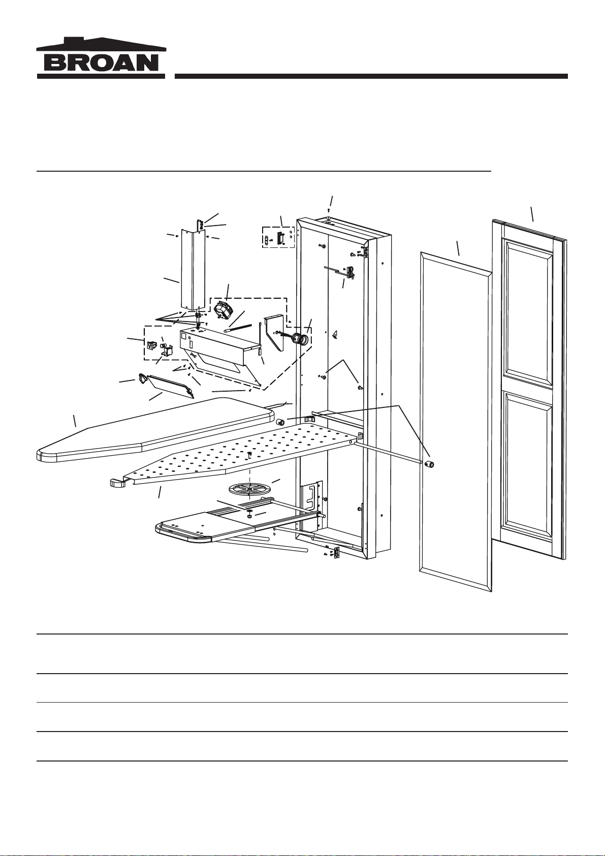
MODELS AVD40B • AVD40KB • AVD40WB
AVD45B • AVD45KB • AVD45WB • AVD50B
CERRADURAS
PLÁSTICAS
DEL
ENVÍO
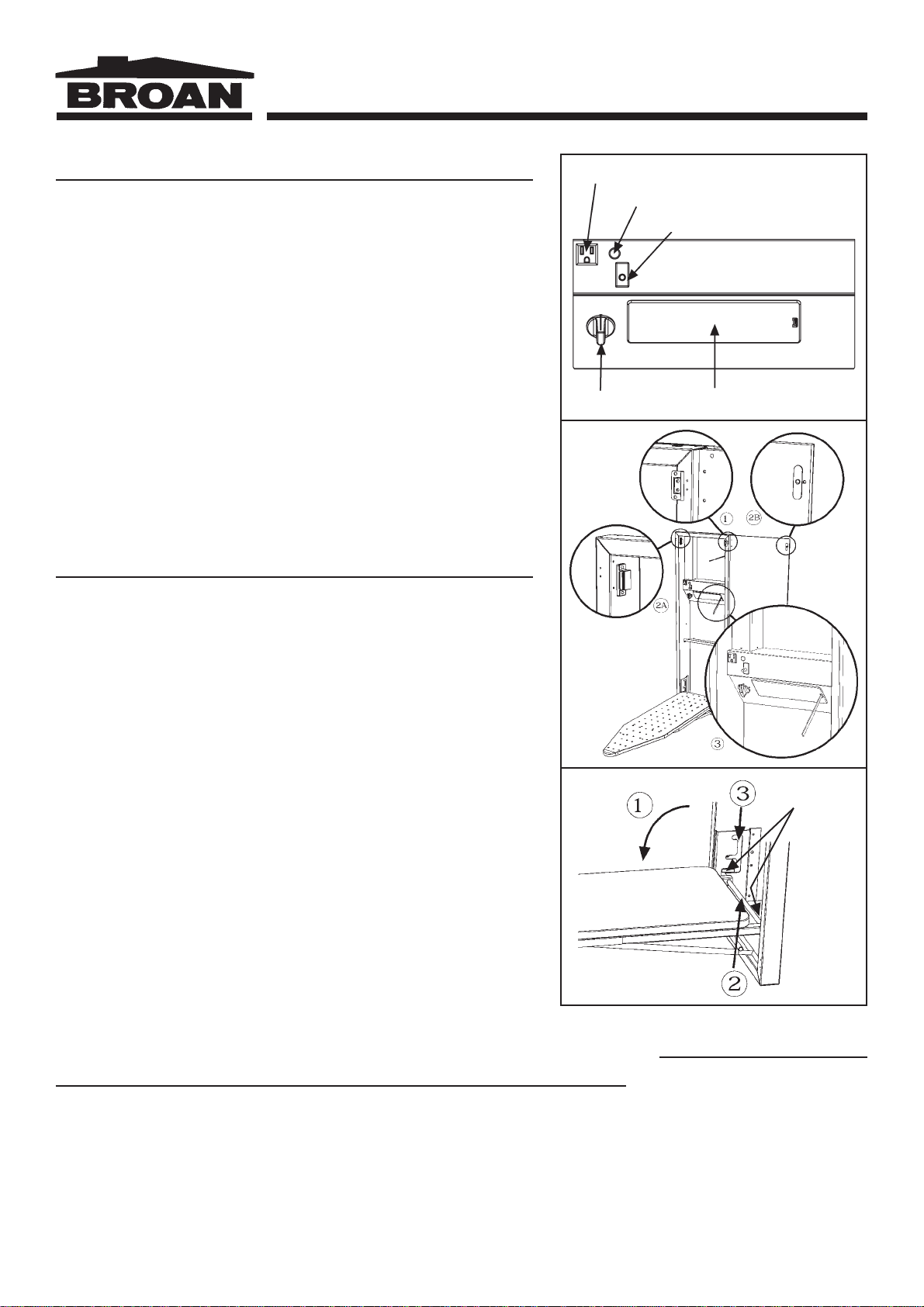
Fig. 3
Fig. 4
Fig. 5
INSTRUCCIONES DE USO (Fig. 3)
Consola de control (Series AVD45 y AVD50)
INTERRUPTOR DE SEGURIDAD
La mesa de planchado oprime este switch cuando es colocada en la posición vertical (al ser
guardado). Esto desconecta el suministro de corriente eléctrica a los controles del centro de
planchado.
INTERRUPTOR DE TIEMPO
Únicamente el foco, el indicador luminoso y el enchufe tienen suministro de corriente eléctrica
cuandoel interruptordetiempoesactivado (girandolaperilla). Seleccioneel tiempoqueestará
planchandogirandolaperilladelinterruptordetiempoenladireccióndelasmanecillasdelreloj.El
interruptorpuedesergiradoderegresoalaposición“0”(Apagado)encualquiermomento.Dévuelta
alaposiciónde“0”(apagado)cuandonoenuso.
INDICADOR LUMINOSO
Cuandoelfocorojoestéprendido,esindicacióndequeelinterruptordetiempoestáactivadoyhay
suministrodecorrienteeléctrica.
FOCO
Elfocoseprenderácuandoelinterruptoresactivado.Serecomiendaelusodeunfocode40Watts
máximo.
ENCHUFE
El Centro de Planchado ha sido equipado con una clavija de 3 patas con conexión a tierra.
PRECAUCIÓN:Asegúresequeelcabledesuplanchanointerfieraconlaoperacióndelinterruptor
de seguridad cuando la mesa de planchado haya sido regresada a su posición de almacenaje
(vertical).
PUERTA (Fig. 4)
ATENCIÓN:LapuertayherrajesestánincluidosenelmodeloAVD40WB,AVD40KB,AVD45WB,
andAVD45KB.Unapuertadecorativaysusherrajespuedensercompradosporseparadoparalos
modelos AVD45B y AVD50B. El peso máximo de la puerta no debe exceder 11.34 kg (25
libras).(Consultelalistadepiezasdeservicio.)
1. MONTAJE DE LA PUERTA
Lasbisagrasdelapuertapuedensercolocadasdelladoderechooizquierdodelgabinete.Ambos
ladosdelgabinetetienenhoyosparaelmontajedelasbisagras.
Uselas dosbisagras(provistas) paramontarla puerta.Lasbisagras debensercolocadas enla
secciónsuperioreinferiordelgabinete.
Montelasbisagrasenelgabineteyfíjelasalapuertausandolostornillosprovistos.
Uselostaponesprovistosparacubrirloshoyosnousadosenelgabinete.
•Cabeza Plana, #6 x 1/2” - Puerta á Bisagra
•Cabeza Cóncava, #6 x 3/8” - Seguro Magnético á Gabinete
•Cabeza Plana, #5 x 3/8” - Contraplaca á Puerta
•Cabeza Plana, #6 x 1/2” - Bisagra á Gabinete
2. INSTALACIÓN DEL SEGURO MAGNÉTICO
Elseguromagnéticodebeserinstaladoenelladoopuestoalasbisagras.
Elseguromagnéticodebeserinstaladoenlasecciónsuperiordelgabineteydelapuerta.Instaleel
seguromagnético2Aenelgabineteusandolostornillos(provistos).
Instalelacontraplaca2Benlapuertausandolostornillos(provistos).
3. REMPLAZO DEL FOCO
Antesdeprocederaremplazarelfoco,asegúresedequehainterrumpidolacorrienteeléctrica(el
interruptordetiempodebeestarenlaposición0).
Inserteundesarmadorpequeñoouncuchillodelgado(comosemuestra),libereelseguromoviéndolo
haciaunladoyextraigaeldifusor(pantalla).
Remplaceelfoco(máximode40Watts).
Vuelvaacolocareldifusor(pantalla)ensulugarenlaconsolaypresionehastaoirunclick
AJUSTEDELAALTURADELAMESADEPLANCHADO
(Fig.5)
MODELO AVD50B
Importante:Quite lascerraduras plásticasdelenvío decada ladodel pivotedel tablero.
Lamesadeplanchadotiene3posicionesdeajusteparalaaltura:
1. Bajelamesadeplanchadoalaprimeraposición(lamasbaja).
2. Sostengalamesadeplanchadoconunamano(nolasujetedelamoldurafrontal)ydetengalabarrapivoteconla
otramano.
3. Ajustealaposicióndeseadalevantandolamesadeplanchado(nolasujetedelamoldurafrontal)moviéndolahacia
laranuraverticaldelajustadorparaseleccionarlaalturadeseada.Deslicelabarrapivotehaciaadelantedentrodela
ranurahorizontalseleccionada.
ATENCIÓN:Paraguardarlamesadeplanchado,éstadebeserpuestaenlaposiciónmasbaja.
MANTENIMIENTO
ESTE CENTRO DE PLANCHADO HA
SIDO EQUIPADO CON UNA CUBIERTA
RESISTENTEALCALOR.PARAEVITAR
DAÑO ALA CUBIERTA(FUNDA)
NO LAVE LA
CUBIERTA
Lasuperficielaminadadelacubiertapuede
ser limpiada con un trapo utilizando un
productolimpiadordomésticonoabrasivo.
ENCHUFE
INDICADOR LUMINOSO
INTERRUPTOR DE SEGURIDAD
INTERRUPTOR DE
TIEMPO FOCO
MODELOS