Broncolor HMI 575.800 User manual

Operating instructions
Bedienungsanleitung
Mode d'emploi
HMI 575.800
www.broncolor.com

1
Operating manual b r o n c o l o r
HMI 575.800
Before use
We are pleased you have chosen a broncolor HMI 575.800 which is a high-quality product in
every respect. If used properly, it will render you many years of good service. Please read all
the information contained in these operating instructions carefully. They contain important
details on the use, safety and maintenance of the appliance. Keep these operating instructions
in a safe place and pass them on to further users if necessary. Observe the safety instructions.
Contents page
Important safety instructions 2
Read before starting up the ballast unit 2
Controls and displays 4
Electronic ballast unit HMI 575.800 4
Controls and displays 5
Lamp base HMI F575.800 5
1. Application area HMI 575.800 6
2. Starting up 6
3. Power regulation 7
4. LED displays 8
5. Lamp base HMI F575.800 8
6. Protection 9
7. Protecting glass 10
8. Fuses 10
9. Mounting 10
10. Service/repair 10
11. Operation of broncolor ballast units with motor generators 11
12. Technical data 11
13. Light shapers for HMI F575.800 12
20. Order numbers for diverse accessories and spare parts 13

2
Important safety instructions !
Read before starting up the unit
The continuous light source broncolor HMI 575.800 may only be used for the professional
illumination of photographic or film scenes and should only be operated by specialized staff.
When using your lighting equipment, it is imperative that the safety precautions below are
followed precisely:
1. For safety reasons the ballast unit may only be operated with an earthed mains (AC-line)
plug. When the unit is switched on, the yellow LED must light up “earth ok”.
2. Read and understand all instructions before using.
3. The UV radiation content of HMI/MSR light is comparable to that of daylight. The
protecting glass has a filter which reduces the amount of UV to acceptable levels for
normal operating distances. When using at a close operating distance unprotected skin
may be exposed only for a limited time.
4. Due to the high intensity try to avoid any eye contact with the light source.
5. Close supervision is necessary when any lamp is used near children. Do not leave lamp
unattended while in use.
6. The lamp base and the accessories mounted onto the lamp may heat up to high
temperatures, so please handle with care.
7. Do not operate units with a damaged cable or if they have dropped or damaged – until
they have been examined by a qualified serviceperson.
8. Position the cable so that it will not be tripped over, pulled, or make contact with hot
surfaces.
9. If an extension cable is necessary, a cable with a current rating at least equal to that of
the lamp should be used. Cables rated for less amperage than the appliance may
overheat. If using a cable reel, uncoil it completely before use, to avoid overheating of the
cable.
10. For safety reasons the lamp base should only be operated with a faultless protection
glass. This provides protection from UV radiation and injuries caused by hot fragments.
11. Do not impede the flow of cooling air circulating through the lamp base and the ballast
unit. During operation the ballast units HMI 575.800 are not stackable. The cooling of the
single units would be strongly affected.

3
12. To protect against effects of radiated heat, the lamp base HMI F575.800 must not be
pointed at flammable surfaces and/or surfaces sensitive to heat, UV sensitive objects or
any living beings from less then 2 meters away. When used at a close-up range, (more
than 2m) limit the exposure time of unprotected skin.
13. Always unplug ballast unit and lamp base before cleaning or servicing and when not in
use. Never jerk cable to pull plug from socket. Grasp plug and pull to disconnect.
14. Let ballast unit and lamp base cool completely before storing. When putting away and
winding up cables, ensure that they do not come into contact with hot parts of the units.
15. To reduce risk of electric shock, do not immerse the lamp base or the ballast unit in water
or other liquids.
16. Lamp bases and ballast units are not suitable for application in wet or explosion-hazard
environments.
17. Protect the ballast unit and the lamp base from water and from excessive exposure to
dust. Avoid operating with wet hands.
18. To reduce the risk of electric shock, do not open this appliance, but take it to a qualified
service person when service or repair work is required. Incorrect reassembly can cause
electric shock when the appliance is used subsequently.
19. The use of an accessory attachment not recommended by the manufacturer may cause a
risk of fire, electric shock, or injury to persons.
20. In order to prolong the service life of the lamp the heat-up process of approx. 1 minute
should not be interrupted.
21. Prior to replacing fuses, lamp or protecting glass, disconnect the ballast unit from mains
power supply.
22. The ballast unit HMI 575.800 can only be used with the lamp base HMI F575.800.

4
Controls and displays
Electronic ballast unit HMI 575.800
1. Mains switch
2. “off“ switch
3. “on“ switch
4. Power regulator (dimmer)
5. LED (green) operation control “on“
6. LED (red) mains control ”supply ok“
7. LED (yellow) earth conductor monitoring “earth on“
8. Lamp plug socket
9. Mains cable socket
10. Fuse 1
11. Fuse 2
12. Grip

5
Controls and displays
Lamp base HMI F575.800
1. Mains switch on/off
2. Change-over switch 575 W / 800 W
3. Rotary knob for focusing
4. Locking slider
5. Bayonet connection with automatic locking
6. Counter-reflector screws
7. Daylight lamp
8. Lamp cable
9. Locking lever

6
1. Application area HMI 575.800
The unit has been specially developed for the professional illumination of photographic or
film scenes. For countries with an earthed power supply use a 3 pin extension cable.
2. Starting up
2.1 Mains power supply/Voltage selector
Connect ballast unit HMI 575.800 to an earthed mains power supply. It adjusts
automatically to the mains (AC-line) voltage applied.
2.2 Earthed power supply
Connect ballast unit HMI 575.800 to the mains supply always with an earthed plug.
2.3 Starting up
The HMI 575.800 is a flicker-free electronic ballast unit which is made for mains voltages
from 90 V to 265 V. It adjusts automatically to the mains (AC-line) voltage applied.
The unit is suited to operate with lamp bases with a hot restrike (HR), which means that
the lamp may be switched on again at any time while hot, making waiting time
unnecessary. For safety reasons, the high ignition voltages required for this purpose
must have a faultless earth conductor, the function of which can be checked with the aid
of the earth monitoring lamp “earth ok” (7). For this reason the ballast unit must always
be connected to the power supply with an earthed mains plug.
1.) Adjust, with a coin or a screw driver, the desired power level with the change-over
switch (2) of the lamp base HMI F575.800, to either 575 W or 800 W.
2.) Equip the lamp base with a daylight lamp of the the corresponding power level (7)
and latch on the protection glass.
Attention: If the lamp base HMI F575.800 is set to the power level 800 W and
by mistake is equipped with a 575 W lamp, the lamp will become
damaged. Furthermore there is the danger that the lamp will explode.
3.) Connect the lamp base with the lamp base cable to the ballast unit and the mains
supply cable of the ballast unit to the earthed mains (AC-line).
4.) Switch on the mains switch (1) of the lamp base (position “on”).

7
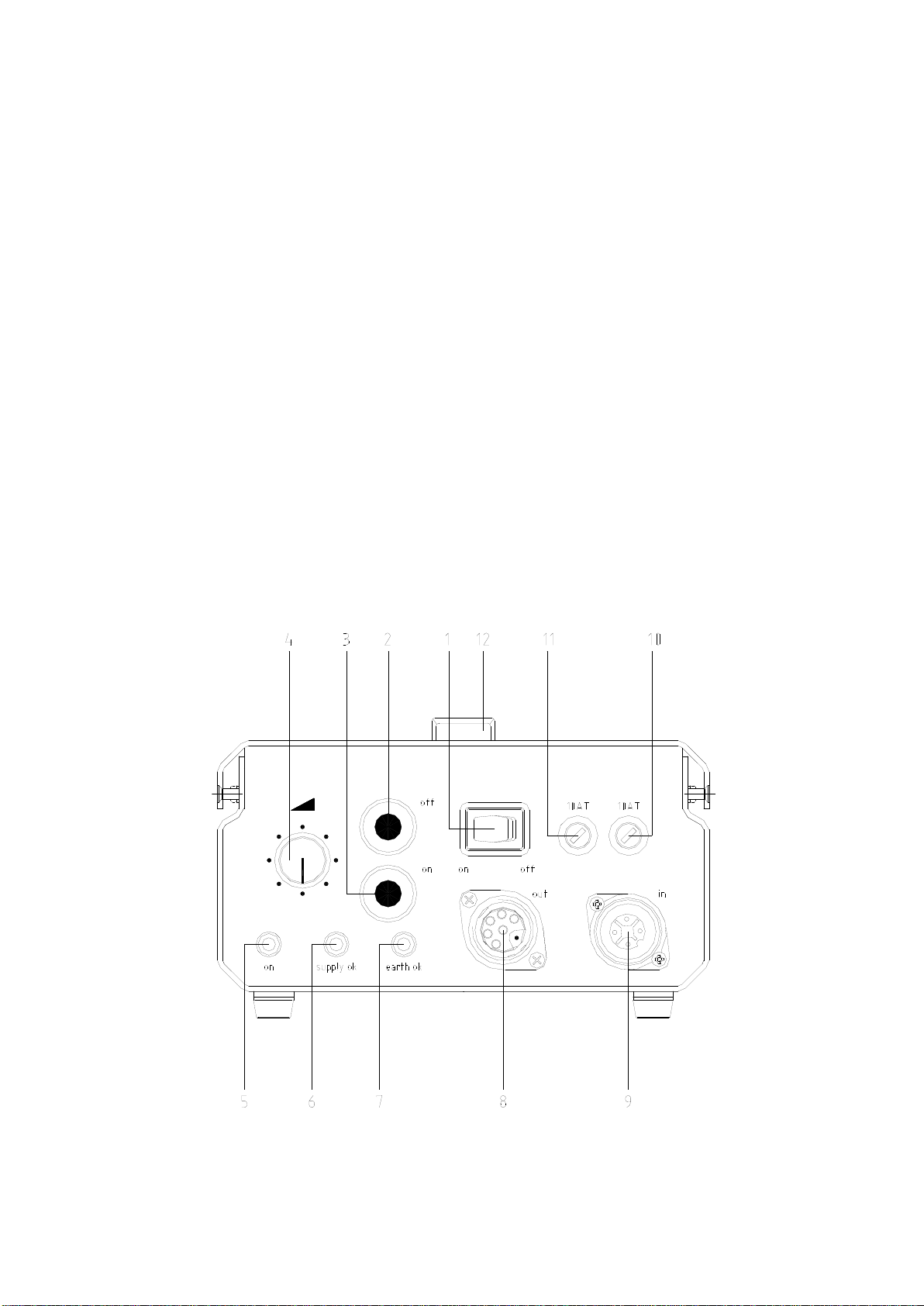
5.) Switch on the mains (AC-line) switch (1) on the ballast unit and check, whether the
yellow LED of the earth monitoring lamp „earth ok“ (7) as well as the red LED “supply
ok” of the mains control light up continuously. Under these conditions the ballast unit
is in operation. The green LED “on” (5) of the operation control lights up. If the mains
(AC-line) switch (1) of the lamp base is „on“, the lamp will light up.
6.) If the yellow LED „earth ok“ (7) does not light up, for safety reasons disconnect
immediately disconnect the ballast unit from the mains (AC-line) supply and control
the earth line. It is not possible to switch on if the red LED “supply ok” is blinking, it
means a technical fault has been detected (see chapter 4: LED displays).
7.) The optimal colour temperature of the lamp is reached after approx. 3 minutes of
operation. The ballast unit HMI 575.800 is equipped with an automatic heat-up
device, so that the operating temperature is reached after only 1 minute. In this
period the unit should only be switched off if absolutely necessary in order to prolong
the service life of the lamp. The heat-up process should always be carried out on full
power.
Attention: If the HMI/MSR lamp cannot be triggered, the ballast unit stops the
trigger process after about 1.5 s. A new attempt to trigger can be
initiated by first pressing the red “off” (2) and then the green “on” (3)
keys. After 10 attempts the unit will block the trigger circuit for about
30 seconds. After that further attempts are possible.
8.) Ensure that the ventilation slots of the ballast unit and the lamp base are
unobstructed during operation.
By pressing the red “off” (2) key on the ballast unit, the lamp will switch off. By pressing
the red “on” (3) key, the unit will operate again.
3. Power regulation
The required light output can be set with the power regulator (4). The adjustment range
extends from 60% - 100% and is equivalent to approximately 1 f-stop. It should be noted
that the colour temperature can change with the power output depending on the type of
lamp used. During heat-up the dimmer is blocked and the power is automatically set to
full until the operating temperature is achieved. The blocking time of the dimmer depends
on the lamp temperature when switching on and can vary between 5 s and 40 s.

8
4. LED displays
4.1 Green LED “on“
If the ballast unit HMI 575.800 is in operation, the green LED „on“ for the operation
control (5) must continuously light up. If the green LED flashes, the temperature control
is activated and regulates slowly the power down to 60%. The lowering of power allows
the user, to perceive the critical temperature value and delays so the switch off the unit
(see chapter 6.2: thermo protection).
4.2 Red LED “supply ok“
If the ballast unit HMI 575.800 is in operation, the red LED “supply ok“ for the mains
control (6) must continuously light up. If the red LED flashes the unit has shut down due
to one of the following reasons:
a) The mains voltage has dropped below 85 V
b) Overload protection of the ignition device: To protect the ignition device, it will be
blocked for about 30 seconds after 10 ignition trials in series .
c) Overheating of the ballast unit
d) Short-circuit in the ballast unit and/or in the lamp base
e) Technical failure
If the red LED flashes, the ballast unit switches off automatically. For safety reasons, the
unit does not switch on automatically, when the technical failure is resolved and it has
returned to normal operation mode (red LED lights up continuously. The lamp must be
switched on again manually.
4.3 Yellow LED “earth ok“
If the ballast unit HMI 575.800 is in operation, the yellow LED “earth ok“ for the earth
conductor monitoring (7) must continuously light up. If the yellow LED „earth ok“ (7) does
not light up, for safety reasons, immediately disconnect the ballast unit from the
mains (AC-line) supply and control the earth line. Ballast units and lamp bases of the
protection class may only be used with a fully-operational earth line.
5. Lamp base HMI F575.800
The lamp base HMI F575.800 can be equipped optionally with a daylight lamp of power
level 575 W or 800 W .
Attention: Adjust beforehand with a coin or a screw driver, the desired power level
with the change-over switch (2) of the lamp base HMI F575.800, to either
575 W or 800 W.

9
5.1 Daylight lamp
The daylight lamp used, operates at a high internal pressure and can explode if used
beyond its service life. The lamp should therefore be exchanged before it reaches the
maximum hours of indicated operation by the lamp manufacturer.
5.2 Protecting glass
The corresponding protecting glass must be used categorically to protect from lamp
explosion and UV-radiation. The lamp base HMI F575.800 is provided with a circuit
breaker. Therefore the unit cannot be switched on without a protecting glass. The UV-
coated protecting glass is also available in a matt version.
5.3 Exchanging lamp
Before replacing the lamp always disconnect the lamp base from the ballast unit!
Attention: Hot lamp !!!
After removing the protecting glass the counter reflector screws (6) must be loosened to
be able to remove the counter reflector over the lamp. Now the lamp can be replaced and
the counter reflector and the protecting glass can be remounted.
6. Protection
6.1 Fan cooling
A low-noised fan cools the lamp base.
6.2 Thermo-protection
If the ballast unit HMI 575.800 is in operation, the green LED „on“ for the operation
control (5) must continuously light up. If the green LED flashes, the temperature control
is activated and regulates slowly the power down to 60%. If the ballast unit reaches the
predefined limit of overheating, the red LED “supply ok” of the mains control (6) starts to
flash and the ballast unit switches off automatically.
For safety reasons the unit does not switch on automatically when the technical failure is
resolved and it has returned to the normal operation mode (red LED lights up
continuously). The lamp must be switched on again manually.
The lamp base HMI F575.800 is also equipped with a thermo-protection and switches off
automatically if overheating. In this case the lamp base must be switched off manually,
with the mains switch (1), to avoid, that it automatically switches on again after the
cooling process.

10
7. Protecting glass
For safety reasons the lamp base HMI F575.800 can only be operated with a mounted
protecting glass and is equipped with a circuit breaker. Therefore the unit cannot be
switched on without a protecting glass. The UV-coated protecting glass is also available
in a matt version.
8. Fuses
The fuses (10 and 11) are located on the operating side of the ballast unit HMI 575.800.
Use exclusively sand filled fuses with the value 10 AT. The use of wrong fuses can
cause extensive damage to the ballast unit or lamp base.
9. Mounting
The stand adapter is located underneath the housing. It allows the insertion of 12 mm
(broncolor®) or 16 mm bolts.
When operating make sure that the unit is securely fixed on the stand. By pulling out the
stop lever it can adjusted in its notches.
10. Service/repair
Your broncolor daylight source is a precision unit. If you take good care, it will work
trouble-free for many years. However, if you should have any failures, please, do not try
to open the unit to repair it yourself. Even if the unit is switched off, dangerous voltages
can remain within the unit. Therefore, always leave servicing and repairs to a broncolor
service agency.

11
11. Operation of broncolor ballast units with
motor generators
broncolor ballast units are suitable for operation with motor generators, provided that their
voltage under all charge conditions (including capacity charge) remains within the tolerance limit
of 90 - 265V. According to experience, it is necessary that only electronic stabilized motor
generators are used.
12. Technical data
with 575 W lamp
with 800 W lamp
Nominal capacity
575 W
800 W
F-stop at a distance of 2 m, 100
ISO, reflector P70 at 1/60 s
8
8 5/10
Illumination in 2 m
Spot: 13’000 lx Angle: approx. 34°
Flood: 3’100 lx Angle: approx. 82°
Spot: 20’000 lx Angle: approx. 34°
Flood: 4’200 lx Angle: approx. 82°
Focusing ratio
1: 4,5
Dimming range (with electronic
ballast unit)
100 % - 60 % 100 % - 60 %
Mains voltage
90 V – 265 V
90 V – 265 V
Ignition possible from
90 V
90 V
Efficiency
0.9
0.9
Power factor
95 % by 230 V / 99 % by 110 V
Flicker
< 5 %
< 5 %
Ambient temperature
-5°C to 45°C
-5°C to 45°C
Operation possible up to
60°C (from 45°C automatic power reduction to 60 %)
Cooling
Stabilized fan
Stabilized fan
Dimensions ballast unit
267 x 184 x 112,5 mm
Dimensions lamp base
321 x 120 x 198 mm
321 x 120 x 198 mm
Weight ballast unit
2,6 kg
2,6 kg
Weight lamp base
2,6 kg
2,6 kg
Power consumption
640 W
900 W
Safety class
I (with strengthened insulation for protection)
Standards
EN60922
EN60529
EN61000-3-2/A14 class C, EN55011
class B
EN60922
EN60529
EN61000-3-2/A14 class C, EN55011
class B
Directives
73/23/CEE, 89/336/CEE
Power requirements
200-240 V / 50-60 Hz: 6 A
100-120 V / 50-60 Hz: 10 A
Daylight lamp
Osram HMI 575 W/SE
Philips MSR 575HR
BA 575 SE HR
Sylvania BA 800 SE HR
Fuses
2 pces, 10 AT (sand-filled)
Subject to change in the interest of product enhancement.

12
13. Light shapers for HMI F575.800
The lamp base HMI F575.800 is equipped with a Pulso bayonet mount. Therefore the
light shapers from the broncolor range listed below are available for light control and light
shaping design.
The accessory used in front of the lamp base HMI F575.800 becomes very hot, which
requires more precaution and consideration, when using one of the below listed articles.
Under some articles you will find the corresponding restrictions for use.
Standard reflector P70 Article no. 33.107.00
Standard reflector P65 Article no. 33.106.00
Narrow angle reflector P45 Article no. 33.104.00
Narrow angle reflector P50 Article no. 33.105.00
Wide angle reflector P120 Article no. 33.112.00
Reflector P-Travel Article no. 33.103.00
Reflector PAR Article no. 33.113.00
Reflector Satellite Staro Article no. 33.151.00
For thermal reasons, only use without Plexi-diffusor
Reflector Satellite Evolution Article no. 33.150.00
Reflector Mini-Satellite Article no. 33.152.00
Special reflectors Para / Para FF / Para FB various article numbers
Softbox Pulsoflex EM 80 x 80 cm Article no. 33.407.00
Only use with adapter ring with integrated reflector (Art. no. 43.100.00)
Softbox Pulsoflex EM 110 x 110 cm Article no. 33.408.00
Only use with adapter ring with integrated reflector (Art. no. 43.100.00)
Softbox Pulsoflex EM 80 x 140 cm Article no. 33.417.00
Only use with adapter ring with integrated reflector (Art. no. 43.100.00)
Softbox Pulsoflex C 100 x 100 cm Article no. 33.442.00
Only use with adapter ring with integrated reflector (Art. no. 43.100.00)
Softbox Pulsoflex C 150 x 150 cm Article no. 33.445.00
Only use with adapter ring with integrated reflector (Art .no. 43.100.00)
Softbox Pulsoflex C 80 x 140 cm Article no. 33.446.00
Only use with adapter ring with integrated reflector (Art. no. 43.100.00)
Area light Mini-Cumulite Article no. 33.141.00
For thermal reasons the glass counter-reflector (33.301.00) may not be used
Area light Hazylight Soft Article no. 33.513.00
For thermal reasons the glass counter-reflector (33.301.00) may not be used

13
Area light Megaflex Article no. 33.521.00
Area light Cumulite 2 Article no. 33.534.00
Area light Megalite (14 different sizes) Article no. 33.540.XX
Article no. 33.541.XX
For thermal reasons, the following light shapers may not be used :
Conical snoot Article no. 33.120.00
Fresnel spot attachment Article no. 33.630.00
Spot attachment Article no. 33.640.00
All honeycomb grids for all metal reflectors various article numbers
All umbrellas Ø 82 cm and Ø 102 cm various article numbers
Reflector Mini-Hazylight Article no. 33.133.00
Area light Hazylight 2 Article no. 33.511.00
Area light Balloon Article no. 33.161.00
20. Order numbers for diverse
accessories and spare parts
Parabolic reflector for HMI F575.800 with 4 lenses (5500 K) Article no. 43.103.55
Parabolic reflector for HMI F575.800 with 4 lenses (5900 K) Article no. 43.103.59
Lamp HMI 575 W/SE for lamp base HMI F575.800 Article no. 44.100.00
Lamp BA 800 SE HR for lamp base HMI F575.800 Article no. 44.104.00
Protecting glass (5500 K) for lamp base HMI F575.800 Article no. 44.101.55
Protecting glass (5500 K), matt, for lamp base HMI F575.800 Article no. 44.102.55
Adapter ring for Pulsoflex C/EM with lamp base HMI F575.800 Article no. 43.100.00
Reflector for Pulso-Flooter S with lamp base HMI F575.800 Article no. 43.101.00
Lamp extension cable, 7.5 m, for HMI 575.800 Article no. 44.200.00
Mains cable EU, black Article no. L6884.00
Mains cable CH, black Article no. L3255.01
Mains cable USA, black Article no. L6884.01
Fuse 10 AT / 5 x 20 mm G Article no. 30908.00
Transport protection cap, grey, for lamp base HMI F575.800 Article no. Z5917.00

1
Bedienungsanleitung b r o n c o l o r
HMI 575.800
Vor dem Benutzen
Es freut uns, dass Sie sich für das in jeder Beziehung hochwertige Produkt broncolor HMI
575.800 entschieden haben. Bei sachgemässer Behandlung wird es Ihnen lange Jahre gute
Dienste leisten. Bitte lesen Sie alle in dieser Bedienungsanleitung aufgeführten Informationen
aufmerksam durch. Sie geben Ihnen wichtige Hinweise für den Gebrauch, die Sicherheit und
die Wartung des Gerätes. Bewahren Sie diese Gebrauchsanweisung sorgfältig auf und geben
Sie diese gegebenenfalls an Nachbenutzer weiter. Beachten Sie die Sicherheitshinweise.
Inhaltsverzeichnis Seite
Wichtige Sicherheitshinweise 2
Vor Inbetriebnahme des Gerätes lesen 2
Bedienungs- und Anzeigeelemente 4
Elektronisches Vorschaltgerät HMI 575.800 4
Bedienungs- und Anzeigeelemente 5
Leuchtenkopf HMI F575.800 5
1. Einsatzgebiet HMI 575.800 6
2. Inbetriebnahme 6
3. Leistungsregelung 7
4. LED-Anzeigen 8
5. Leuchtenkopf HMI F575.800 8
6. Schutzeinrichtungen 9
7. Schutzglas 10
8. Sicherung 10
9. Montage 10
10. Wartung/Reparaturen 10
11. Betrieb von broncolor Vorschaltgeräten 11
an Motor-Generatoren 11
12. Technische Daten 11
13. Lichtformer zu HMI F575.800 12
20. Bestellnummern für diverse Zubehör- und Ersatzteile 13

2
Wichtige Sicherheitshinweise !
Vor Inbetriebnahme des Gerätes lesen
Die Dauerlichtquelle broncolor HMI 575.800 darf nur für die professionelle Ausleuchtung von
Szenen für photographische oder filmische Zwecke eingesetzt werden und ist ausschliesslich
durch ausgebildetes Fachpersonal zu bedienen. Wenn Sie Ihre Beleuchtungsausrüstung
einsetzen, müssen die nachfolgenden Sicherheitsvorkehrungen zwingend eingehalten werden:
1. Aus Sicherheitsgründen darf das Vorschaltgerät nur an Netzsteckern mit Erdanschluss
betrieben werden. Bei eingeschaltetem Geräteschalter muss die gelbe LED Anzeige
"earth ok" der Schutzleiter-Kontrolle brennen.
2. Machen Sie sich gründlich mit der Bedienungsanleitung vertraut.
3. HMI/MSR-Licht enthält ähnlich wie Tageslicht einen gewissen Anteil an UV-Strahlung.
Das Schutzglas enthält eine Filterschicht, die den UV-Anteil für normale Einsatzdistanzen
auf ungefährliche Werte reduziert. Für Einsatz im Nahbereich ist die Bestrahlung
ungeschützter Haut zeitlich zu beschränken.
4. Auf Grund der grossen Intensität ist Blickkontakt mit der Lichtquelle zu vermeiden.
5. Achten Sie besonders in Gegenwart von Kindern auf Ihre Ausrüstung. Lassen Sie die
Geräte nicht unbeaufsichtigt.
6. Denken Sie daran, dass im Betrieb hohe Temperaturen entstehen und die Berührung
von heissen Teilen Verletzungen verursachen kann.
7. Verwenden Sie nur intakte Anschlusskabel und lassen Sie Geräte, die fallengelassen
wurden oder beschädigt sind, vor Wiederinbetriebnahme von einer Fachperson prüfen.
8. Achten Sie beim Verlegen von Kabeln darauf, dass diese keine heissen Teile berühren
und für Personen keine Stolpergefahr darstellen.
9. Falls ein Verlängerungskabel nötig ist, so muss es für das zu versorgende Gerät
ausreichend dimensioniert sein. Kabel, die nicht für die betreffende Stromstärke
ausgelegt sind, können sich überhitzen. Bei Verwendung einer Kabelrolle muss diese vor
Gebrauch vollständig entrollt werden, um eine Überhitzung des Kabels zu vermeiden.
10. Aus Sicherheitsgründen darf der Leuchtenkopf nur mit intaktem Schutzglas betrieben
werden. Dieses dient zum Schutz vor UV- Strahlen und Verletzungen durch heisse
Splitter.
11. Die durch Leuchtenkopf und Vorschaltgerät zirkulierende Kühlluft darf in ihrem Fluss
nicht behindert werden. Während des Betriebes sind die Vorschaltgeräte HMI 575.800
nicht stapelbar. Die Kühlung der einzelnen Geräte würde dadurch zu stark beeinträchtigt.

3
12. Mit Rücksicht auf die Wärmestrahlung darf der Leuchtenkopf HMI F575.800 nur in einem
Minimalabstand von 2Meter gegen brennbare und/oder wärmeempfindliche
Oberflächen, UV-empfindliche Objekte oder Lebewesen gerichtet werden. Für den
Einsatz im Nahbereich (grösser 2 Meter) ist die Bestrahlung ungeschützter Haut zeitlich
zu beschränken.
13. Ziehen Sie stets den Stecker des Anschlusskabels heraus, wenn Sie das Vorschaltgerät
oder den Leuchtenkopf reinigen oder pflegen, bzw. wenn sie nicht gebraucht werden.
Zum Ausstecken nie am Kabel selber ziehen, sondern immer direkt am Steckergehäuse.
14. Lassen Sie das Vorschaltgerät und den Leuchtenkopf abkühlen, bevor Sie diese
verstauen. Achten Sie beim Wegräumen und Aufrollen von Kabeln darauf, dass diese
keine heissen Geräteteile berühren.
15. Das Vorschaltgerät oder der Leuchtenkopf dürfen nicht in Wasser oder andere
Flüssigkeiten getaucht werden. Dabei könnten berührungsgefährliche
Spannungsentladungen entstehen.
16. Leuchtenkopf und Vorschaltgerät sind nicht geeignet für den Einsatz in nasser oder
explosionsgefährdeter Umgebung.
17. Das Vorschaltgerät und der Leuchtenkopf ist vor Spritz- und Tropfwasser sowie
erheblicher Staubeinwirkung zu schützen. Die Bedienung mit nassen Händen ist zu
vermeiden.
18. Um gefährliche elektrische Schläge zu vermeiden, Vorschaltgerät und Leuchtenkopf nie
öffnen. Service- oder Reparaturarbeiten immer durch eine Fachperson ausführen lassen.
Bei unsachgemässem Zusammenbau können selbst am geschlossenen Gerät
gefährliche Berührungsspannungen auftreten.
19. Um die Gefahr eines Feuers, eines elektrischen Schlages oder einer Verletzung zu
vermeiden, verwenden Sie ausschliesslich das vom Hersteller empfohlene Zubehör.
20. Mit Rücksicht auf die Lebensdauer des Brenners soll der Aufheizvorgang von ca. 1 Min.
nicht abgebrochen werden.
21. Vor dem Auswechseln der Sicherungen, dem Brenner oder dem Schutzglas ist das
Vorschaltgerät vom Netz zu trennen.
22. Das Vorschaltgerät HMI 575.800 darf nur an den Leuchtenkopf HMI F575.800
angeschlossen werden.

4
Bedienungs- und Anzeigeelemente
Elektronisches Vorschaltgerät HMI 575.800
1. Netzschalter
2. Taste “aus“ (off)
3. Taste “ein“ (on)
4. Leistungsregler (Dimmer)
5. LED (grün) für Betriebskontrolle “on“
6. LED (rot) für Netzkontrolle ”supply ok“
7. LED (gelb) für Schutzleiter-Kontrolle “earth ok“
8. Buchse für Leuchtenstecker
9. Buchse für Netzkabel
10. Sicherung 1
11. Sicherung 2
12. Handgriff
4 1 12 11 102
985 6 7
3

5
Bedienungs- und Anzeigeelemente
Leuchtenkopf HMI F575.800
1. Netzschalter ein/aus (“on“ / “off“)
2. Umschalter 575 W / 800 W
3. Drehknopf Fokussierung
4. Verriegelungsschieber
5. Bajonett-Anschluss mit automatischer Verriegelung
6. Gegenreflektor-Schrauben
7. Tageslicht-Brenner
8. Leuchtenkabel
9. Rasthebel

6
1. Einsatzgebiet HMI 575.800
Das Gerät ist für die professionelle Ausleuchtung von Szenen für photographische oder
filmische Zwecke konzipiert worden. In Ländern mit geerdetem Stromnetz ist ein 3-
poliges Verlängerungskabel zu verwenden.
2. Inbetriebnahme
2.1 Netzspannung/Spannungswähler
Vorschaltgerät HMI 575.800 an geerdetes Netz anschliessen. Es stellt sich automatisch
auf die vorhandene Netzspannung ein.
2.2 Geerdetes Netz
Vorschaltgerät HMI 575.800 immer mit geerdetem Netzstecker am Stromnetz
anschliessen.
2.3 Inbetriebnahme
HMI 575.800 ist ein flickerfreies, elektronisches Vorschaltgerät und ist für
Netzspannungen von 90 V bis 265 V ausgelegt. Die Anpassung an die jeweilige
Netzspannung erfolgt automatisch .
Die Geräte sind geeignet für den Betrieb von Leuchten mit Heisswiederzündung (Hot
Restrike HR), d.h. der Brenner sind auch in heissem Zustand jederzeit wieder zündbar.
Wartezeiten beim Wiedereinschalten im heissen Zustand entfallen. Die dazu
notwendigen hohen Zündspannungen erfordern aus Sicherheitsgründen eine
einwandfreie Erdzuleitung, deren Funktion unter Mithilfe der gelben Schutzleiter-
Kontrollleuchte “earth ok“ (7) überprüft werden kann. Aus diesem Grund muss das
Vorschaltgerät immer mit geerdetem Netzstecker am Stromnetz angeschlossen werden.
1.) Am Umschalter (2) des Leuchtenkopfes HMI F575.800 mit einer Münze oder einem
Schraubenzieher die gewünschte Leistungsstufe einstellen, d.h. entweder 575 W
oder 800 W.
2.) Leuchtenkopf mit dem Tageslicht-Brenner (7) der entsprechenden Leistungsstufe
bestücken und anschliessend das Schutzglas einklinken.
Achtung: Ist der Leuchtenkopf HMI F575.800 für die Leistungsstufe 800 W
eingestellt und wird dieser fälschlicherweise mit einem Brenner 575 W
bestückt, resultiert daraus ein Defekt des Brenners. Zudem besteht die
Gefahr, dass der Brenner platzt.
3.) Leuchtenkopf mittels Leuchtenkabel an das Vorschaltgerät und dieses mittels
Netzkabel an das geerdete Netz anschliessen.
4.) Der Netzschalter (1) des Leuchtenkopfes einschalten (Position “on“).
Table of contents
Languages:
Other Broncolor Lighting Equipment manuals
Popular Lighting Equipment manuals by other brands

WalimeXPro
WalimeXPro LED 128 instruction manual

Light4Me
Light4Me VENOM BEAM 250 user manual

Show Tec
Show Tec LED Pinspot DMX V3 quick start guide

Dop Choice
Dop Choice SNAPBAG operating instructions

superbrightleds
superbrightleds BRI816-B-D user manual

Eco-Smart
Eco-Smart AL13-8FT-RGBWW-1-A Use and care guide

Night Stick
Night Stick XPR-5560GA instruction manual

STUDIODUE
STUDIODUE Single 40 manual

Lightmybricks
Lightmybricks LEGO TALES OF THE SPACE AGE 21340 installation guide

Hellermann Tyton
Hellermann Tyton SpotClip-Box operating instructions

Claypaky
Claypaky Odeon Flood Series instruction manual

pro master
pro master Specialist LED1000D manual