Light4Me VENOM BEAM 250 User manual

1
LIGHT4ME VENOM BEAM 250
INSTRUKCJA OBSŁUGI
USER MANUAL

2
ENGLISH
1 SAFETY INSTRUCTIONS
This device has left the factory in perfect condition. In order to maintain this condition and to
ensure a safe operation, it is absolutely necessary for the user to follow the safety instructions
and warning notes written in this user manual.
If the device has been exposed to temperature changes due to environmental changes, do not
switch it on immediately. The arising condensation could damage the device.
Leave the device switched off until it has reached room temperature.
This device falls under protection-class I. Therefore it is essential that the device be earthed.
The electric connection must carry out by qualified person.
The device shall only be used with rate voltage and frequency.
Make sure that the available voltage is not higher than stated at the end of this manual.
Make sure the power cord is never crimped or damaged by sharp edges. If this would be the
case, replacement of the cable must be done by an authorized dealer.
Always disconnect from the mains, when the device is not in use or before cleaning it. Only
handle the power cord by the plug. Never pull out the plug by tugging the power cord.
During initial start-up some smoke or smell or smell may arise. This is a normal process and does
not necessary mean that the device is defective, it should decrease gradually.
Please don’t project the beam onto combustible substances.
Fixtures cannot be installed on combustible substances, keep more than 50cm distance with
wall for smooth air flow, so there should be no shelter for fans and ventilation for heat radiation.
If the external flexible cable or cord of this luminaire is damaged, it shall be exclusively replaced
by the manufacturer of his service agent or a similar qualified person in order to avoid a hazard.

3
2 UNPACKING
Thank you for choosing our LED 250W moving head light. For your own safety, please read this
manual before installing the device. This manual covers the important information on
installation and applications. Please install and operate the fixture with following instructions.
Meanwhile, please keep this manual well for future needs.
The VENOM BEAM 250W is made of a new type of high temperature strength of engineering
plastic and cast aluminum casing with nice outlook. The fixture is designed and manufactured
strictly following CE standards, complying with international standard DMX512 protocol. It’s
available independently controlled and linkable with each other for operation. And it is
applicable for large-scale live performances, theater, studio, nightclubs and discos.
The VENOM BEAM 250W Moving head light which features high brightness and stability.
Please carefully unpack it when you receive the fixture and check whether it is damaged
during the transportation. And please check whether the following items are included inside
the box:

4
3 FEATURES & SPECIFICATIONS
Features
·250W High Output White LED
·50,000 hours lifespan and low power consumption
·Beam Angle 3°, focus function
·High light output, LUX28600@5M at White light
·Temperature protect function, when the internal Temperature is up to 40° then the fans
begin to work, when the internal temperature is up to 70°and the brightness reduce half.
·Color Wheel: 7 colors +white, color fine tuning, rotation with variable direction and speed
·1 static Gobo Wheel: 7 gobos +white, wheel rotation and shake
·1 Rotation Gobo Wheel: 8 gobos +white, wheel rotation and shake
·Prism: 16-facet Prism & Honeycomb Prism, bi-directional rotatable at variable speeds
·High speed strobe effect with 1-25 flashers per second
·Frost Effect
·Internal program available
·16/18 DMX Channels USITT DMX-512
·DMX 512, master-slave and sound activated controllable or auto operation
·Colorful LCD display
·Efficient low noise fan cooling system
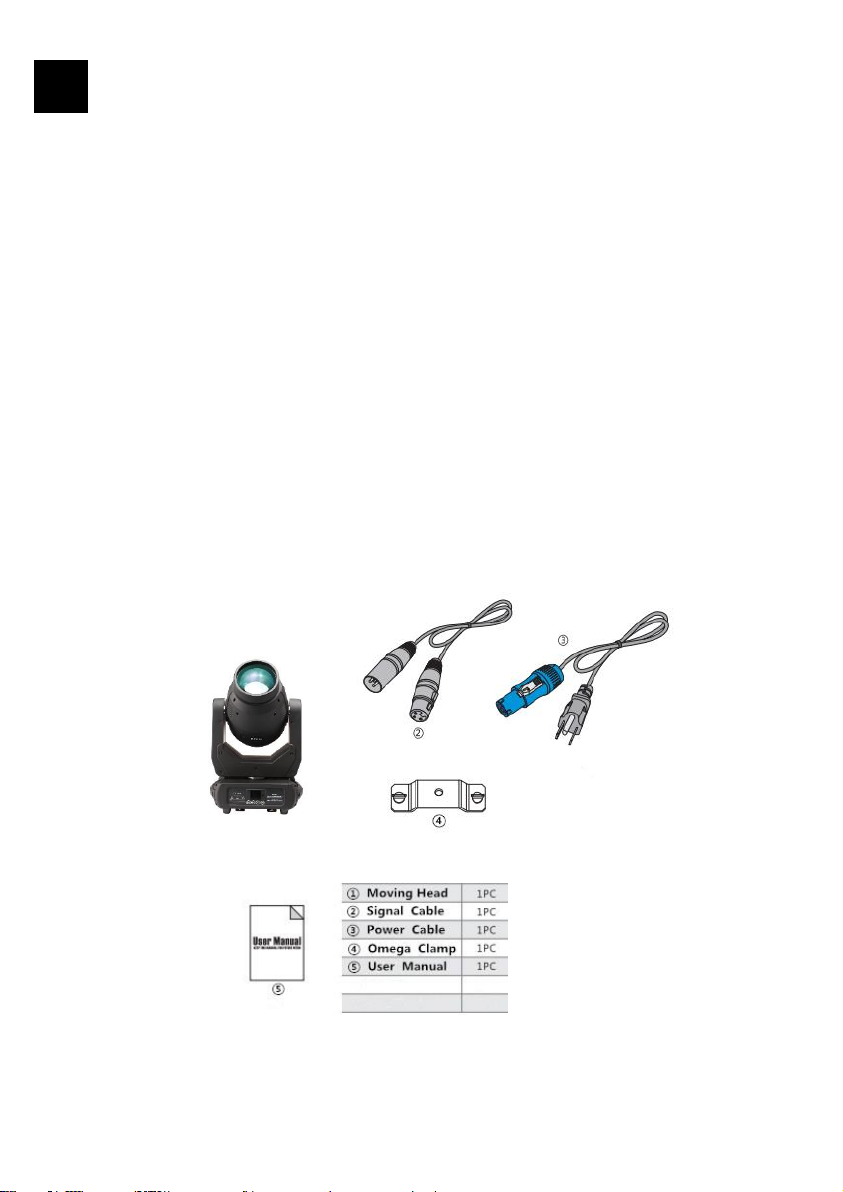
·PowerCon IN/OUT
·3-pin & 5-pin XLR connectors IN/OUT
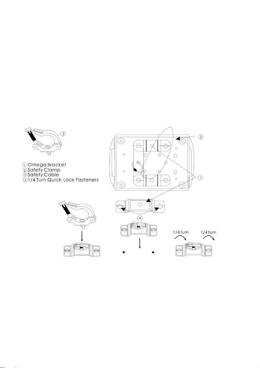
·Two 1/4 turn fastening Omega Clamps
·IP 20 protection rating
Specifications
Input Voltage: AC90-260V 50/60Hz
Light Source: 250W High Output White LED
Control Signal: DMX 512, master-slave and sound activated or auto operation
Control Channel: 16/18 DMX Channels USITT DMX-512
Power Consumption: 350W
Dimensions: 320(L)*220(W)*480(H)mm
Packing size: 365(L)*290(W)*615(H)mm
Net Weight: 13.50kg,Gross Weight: 16.50kg

5
4 PHOTOMETRIC DATA
5 OPERATION INSTRUCTIONS
∙The moving head is for spot effect for on-site decoration purpose.
∙Don’t turn on the fixture if it’s been through severe temperature difference like after
transportation because it might damage the light due to the environment changes. So
make sure to operate the fixture until it is in normal temperature.
∙This light should be keep away from strong shaking during any transportation or
movement.
∙Don’t pull up the light by only the head, or it might cause damages to the mechanical
parts.
∙Don’t expose the fixture in overheat, moisture or environment with too much dust when
installing it. And don’t lay any power cables on the floor. Or it might cause electronics
shock to the people.
∙Make sure the installation place is in good safety condition before installing the fixture.
∙Make sure to put the safety chain and check whether the screws are screwed properly
when installing the fixture.
∙Make sure the lens are in good condition. It’s recommended to replace the units if there
are any damages or severe scratch.

6
∙Make sure the fixture is operated by qualified personnel who know the fixture before
using.
∙Keep the original packages if any second shipments is needed.
∙Don’t try to change the fixtures without any instruction by the manufacturer or the
appointed repairing agencies.
∙It is not in warranty range if there are any malfunctions from not following the user
manual to operate or any illegal operation, like shock short circuit, electronic shock, lamp
broke, etc.
6 INSTALLATIONS
Cautions: For added protection mount the fixtures in areas outside walking paths, seating
areas, or in areas were the fixture might be reached by unauthorized personnel.
Before mounting the fixture to any surface, make sure that the installation area can hold a
minimum point load of 10 items the device’s weight.
Fixture installation must always be secured with a secondary safety attachment, such as an
appropriate safety cable.
Never stand directly below the device when mounting, removing, or servicing the fixture.
From a ceiling, or set on a flat level surface (see illustration below). Be sure this fixture is kept
at least 0.5m (1.5ft) away from any flammable materials (decoration etc.).
Always use and install the supplied safety cable as a safety measure to prevent accidental
damage and/or injury in the event the clamp fails.
Mounting points: Overhead mounting requires extensive experience, including amongst
others calculating working load limits, a fine knowledge of the installation material being used,
and periodic safety inspection of all installation material and the fixture. If you lack these
qualifications, do not attempt the installation yourself. Improper installation can result in
bodily injury.

7
Be sure to complete all rigging and installation procedures before connecting the main power
cord to the appropriate wall outlet.
Clamp Mounting: The LED moving head provides a unique mounting bracket assembly that
integrates the bottom of the base, and the safety cable rigging point in one unit (see the
illustration below). When mounting this fixture to truss be sure to secure an appropriately
rated clamp to the included omega bracket using a M10 screw fitted through the center hole
of the “omega bracket”. As an added safety measure be sure to attached at least one properly
rated safety cable to the fixture using on of the safety cable rigging point integrated in the
base assembly.
Regardless of the rigging option you choose for your LED moving head, always be sure to
secure your fixture with a safety cable. The fixture providers a built-in rigging point for a safety
cable on the hanging bracket as illustrated above. Be sure to only use the designated rigging
point for the safety cable and never secure a safety cable to a carrying handle.

8
7 DMX-512 CONTROL CONNECTIONS
Connect the provided XLR cable to the female 3-pin XLR & 5-pin XLR output of your controller
and the other side to the male 3-pin XLR & 5-pin XLR input of the moving head. You can chain
multiple moving head together through serial linking. The cable needed should be two core,
screened cable with XLR input and output connectors. Please refer to the diagram below.
For installations where the DMX cable has to run a long distance or is in an electrically noisy
enviroment, such as in a discotheque, it is recommended to use a DMX terminator. This helps
in preventing corruption of the digital control signal by electrical noise. The DMX terminator is
simply an XLR plug with a 120 Ω resistor connected between pins 2 and 3, which is then
plugged into the output XLR socket of the last fixture in the chain. Please see illustrations
below.
.

9
8 MENU OPERATIONS
MENU
Address Set [Set Address Numbers]
[DMX]
Run Mode [AUTO] Auto 1- Auto 2
[SOUND]
[MANUAL] Manual Test Function and Operation
Pan reverse
Tilt reverse
Display
Screen Reverse
Setup [Advanced Setting] Channel (16/18CH Select)
Sensitivity (01-100)
Motor zero
Reset
Factory Set
Ver V1
System Information DMX Address
Temperature

10
9 DMX CHANNELS
16/18 channel mode sheet
18CH
16CH
Function
Channel Value
Description
CH1
CH1
Pan
0-255
0-540°
CH2
Pan fine
0-255
Pan Fine
CH3
CH2
Tilt
0-255
0-270°
CH4
Tilt Fine
0-255
Tilt Fine
CH5
CH3
X, Y speed
0-255
From fast to slow
CH6
CH4
LED Dimmer
0-255
From dark to bright
CH7
CH5
LED Strobe
0-7
Turn on
8-250
Strobe from slow to fast
251-255
Turn on
CH8
CH6
7 color +
White
0-15
White Lighting
16-31
Color 1
32-47
Color 2
48-63
Color 3
64-79
Color 4
80-95
Color 5
96-111
Color 6
112-127
Color 7
128-191
CW from slow to fast
192-255
CCW from slow to fast
CH9
CH7
Color effect
0-10
No function
11-209
Color fine tuning
210-255
Color shake from fast to slow

11
CH10
CH8
Static gobo
wheel
0-6
open
7-13
Gobo1
14-20
Gobo2
21-27
Gobo3
28-34
Gobo4
35-41
Gobo5
42-48
Gobo6
49-55
Gobo7
56-63
Gobo 8
64-70
Gobo 8 shake
71-77
Gobo 7 shake
78-84
Gobo 6 shake
85-91
Gobo 5 shake
92-98
Gobo 4 shake
99-105
Gobo 3 shake
106-112
Gobo 2 shake
113-119
Gobo 1 shake
120-127
open
128-191
Gobo rotate CW from slow to fast
192-255
Gobo rotate CCW from slow to fast
CH11
CH9
7 rotation
gobos
+White
0-15
open
16-31
Gobo1
32-47
Gobo2
48-63
Gobo3
64-79
Gobo4
80-95
Gobo5
96-111
Gobo6
112-127
Gobo7

12
128-191
Gobo Rotate CW from slow to fast
192-255
Gobo Rotate CCW from slow to fast
CH12
CH10
Gobo
Rotation
0-15
open
16-95
Gobo Fine 0-250
96-135
Gobo Rotating 0-90
136-155
Gobo Rotating 0-250
156-175
Gobo Rotating 0-360
176-215
Gobo self-rotating CW from slow to fast
216-255
Gobo self-rotating CCW rotating from
slow to fast
CH13
CH11
Focus
0-255
Gobo hazy to clear
CH14
CH12
Prism 1
0-63
Open
64-255
Prism In
CH15
CH13
Prism 2
0-63
Open
64-255
Prism In
CH16
CH14
Prism
Rotation
0-15
open
16-95
Prism Fine 0-250
96-135
Prism Rotating 0-90
136-155
Prism Rotating 0-250
156-175
Prism Rotating 0-360
176-215
Prism self-rotating CW from slow to fast
216-255
Prism self-rotating CCW rotating from
slow to fast
CH17
CH15
Frost
0-4
No function
5-127
Frost from shallow to deep
128-191
Frost shake
192-255
Frost effect
CH18
CH16
self-setting
0-7
No action

13
Program
8-131
Auto mode
132-249
Soud mode
250-253
Reset
254-255
No action
10 MAINTENANCE AND CLEANING
The following points have to be considered during the inspection:
1) All screws for installing the devices or parts of the device have to be tightly connected and
must not be corroded.
2) There must not be any deformations on the housing, color lenses, fixations and installation
spots (ceiling, suspension, trussing).
3) Mechanically moved parts must not show any traces of wearing and must not rotate with
unbalances.
4) The electric power supply cables must not show any damage, material fatigue or
sediments.
Further instructions depending on the installation spot and usage have to be adhered by a
skilled installer and any safety problems have to be removed.
In order to make the lights in good condition and extend the life time, we suggest a regular
cleaning to the lights.
1) Clean the inside and outside lens each week to avoid the weakness of the lights due to
accumulation of dust.
2) Clean the fan each week.
3) A detailed electric check by approved electrical engineer each three month, make sure that the
circuit contacts are in good condition, prevent the poor contact of circuit from overheating.
We recommend a frequent cleaning of the device. Please use a moist, lint-free cloth. Never use
alcohol solvents.
There are no serviceable parts inside the device. Please refer to the instructions under
“Installation instructions”.
Should you need any spare parts, please order genuine parts from your local dealer.

14
WARNING! THE DEVICE MUST NOT BE DISPOSED OF WITH HOUSEHOLD WASTE. This
symbol indicates that this product must not be disposed of with household waste,
according to the EU and your national law. In order to prevent potential damage to the
environment or health, the used product must be recycled. In accordance with current
legislation, unusable electrical and electronic devices must be collected separately at the
designated facilities for recycling, acting on the basis of applicable environmental standards.
Information about used electrical and electronic equipment
The main goal of European and national law regulations is to reduce the amount of waste
produced from used electrical and electronic equipment, to ensure an appropriate level of
collection, recovery and recycling of used equipment, and to increase public awareness of its
harmfulness to the environment, at each stage of use of electrical and electronic equipment.
Therefore, it should be pointed out that households play a key role in contributing to reuse and
recovery, including recycling of used equipment. The user of electrical and electronic equipment
– intended for households – is obliged to return it to authorized collector after its use. However,
it should be remembered that products classified as electrical or electronic equipment should
be disposed of at authorized collection points.

15
POLSKI
1. INSTRUKCJE BEZPIECZEŃSTWA
UWAGA
PROSIMY ZACHOWAĆ OSTROŻNOŚĆ PODCZAS PRACY. PRZY DOTYKANIU PRZEWODÓW MOŻNA
DOZNAĆ PORAŻENIA PRĄDEM.
Urządzenie opuściło fabrykę w dobrym stanie. W celu utrzymania tego stanu, należy stosować
się do ostrzeżeń i informacji zawartych w tej instrukcji.
WAŻNE
USZKODZENIA SPOWODOWANE ZIGNOROWANIEM INSTRUKCJI I UŻYTKOWANIEM PRODUKTU
NIEZGODNIE Z PRZEZNACZENIEM POWODUJĄ UTRATĘ GWARANCJI. PRODUCENT NIE PONOSI
ODPOWIEDZIALNOŚCI ZA SZKODY Z TYM ZWIĄZANE.
Jeśli urządzenie zostało narażone na zmiany temperatury, nie należy włączać go bezpośrednio
po przeniesieniu do pomieszczenia. Nagromadzenie wilgoci może spowodować uszkodzenia
produktu. Należy odczekać aż głowica osiągnie temperaturę pokojową.
Zasilanie urządzenia musi być uziemione, wszelkie połączenia elektryczne muszą być wykonane
przez wykwalifikowaną osobę. Przed podłączeniem należy upewnić się, że napięcie jest zgodne
z zalecanym.
Upewnij się, że przewód zasilający nie jest uszkodzony, w przeciwnym razie należy go wymienić
na nowy.
Zawsze odłączaj głowicę z zasilania jeśli urządzenie nie jest używane lub jest czyszczone. Nigdy
nie odłączaj z prądu ciągnąc za przewód.
Podczas pierwszego użycia może pojawić się odrobina dymu i zapachu spalenizny, jest to
normalny efekt. Nie należy się tym przejmować, po kilku użyciach powinien ustąpić.
Nie należy generować projekcji na materiały palne.
Urządzenie nie może być umieszczane na materiałach palnych, takich jak dywany, kartony, itp.
Należy zachować minimum 50cm odległości od ściany, aby zapewnić odpowiedni przepływ
powietrza. Upewnij się również, że otwory wentylacyjne nie są zablokowane.
Jeśli zauważysz uszkodzenie obudowy lub przewodu zasilającego należy skontaktować się
z serwisem, nie należy użytkować produktu.

16
2. WYPAKOWYWANIE
Dziękujemy za wybór naszej głowicy. Dla własnego bezpieczeństwa zapoznaj się z instrukcją
przed użyciem. Zawiera ona ważne informacje na temat bezpieczeństwa instalacji i użytkowania.
Instrukcję należy zachować dla przyszłych potrzeb.
Venom Beam 250 został wykonany z wysokiej jakości nowoczesnego i odpornego za wysokie
temperatury plastiku oraz aluminium. Urządzenie zostało zaprojektowane by spełniać
standardy CE oraz współpracować z protokołem DMXX512. Urządzenia można używać
pojedynczo lub w większej ilości. Oświetlenie to bardzo dobrze się sprawdza w wystąpieniach
scenicznych, teatrach, studiach, klubach i dyskotekach.
Po otrzymaniu przesyłki prosimy o szczegółowe sprawdzenie zawartości, czy nie została
uszkodzona I jest kompletna:
1. Głowica
2. Przewód DMX
3. Przewód zasilający PowerCon
4. Uchwyt montażowy
5. Instrukcja obsługi
3 CECHY I SPECYFIKACJA
CECHY
·250W biała dioda LED
·50 000 godzin żywotności diody i niskie zużycie energii
·Kąt świecenia 3o, zmotoryzowany focus
·Wysoka wydajność świetlna, 28600LUX@5M przy białym świetle
·Funkcja ochrony przed przegrzaniem, kiedy temperatura osiąga 40oC wentylatory zaczynają
pracować, przy temperaturze 70oC moc promienia zmniejsza się o połowę

17
·Koło kolorów: 7 kolorów
·
+biały, rotacja w obydwu kierunkach o różnych prędkościach
·Koło statycznych: 7 gobo + open, gobo scroll, gobo shake
·Koło obrotowych gobo: 8 gobo + open, gobo scroll, gobo shake
·Pryzma: 16-ramienna obrotowa oraz obrotowa Pryzma typu plaster miodu
·Filtr Frost
·Stroboskop o dużej częstotliwości 1-25 błysków na sekundę
·Wbudowane programy
·16/18 kanałów DMX
·Tryby pracy: auto, sound, master/slave, DMX512
·Kolorowy wyświetlacz LCD
·Cichy system chłodzenia
·POWERCON IN/OUT
·Uchwyty szybkiego montażu
·Stopień ochrony IP20
SPECYFIKACJA
Zasilanie: AC90-260V 50/60Hz
Źródło światła: 250W biała dioda LED
Tryby pracy: DMX 512, master/slave, sound, auto
Kanały DMX: 16/18 DMX
Zużycie energii: 350W
Wymiary: 320(długość)*220(szerokość)*480(wysokość)mm
Waga: 13.5kg, Waga brutto: 16.5kg
4 DANE FOTOMETRYCZNE

18
5 INSTRUKCJA UŻYTKOWANIA
∙Ruchoma głowica do efektów typu beam w przemyśle dekoracyjnym i scenicznym.
∙Urządzenie nie powinno być narażone na silne wstrząsy podczas transport lub
przenoszenia
∙Nie podnoś głowicy chwytając za elementy ruchome, może to spowodować
uszkodzenie części mechanicznych.
∙Nie narażaj urządzenia na przegrzanie, wilgoć i duże zakurzenie otoczenia. Nie powinno
się również kłaść przewodów zasilających na ziemi, aby uniknąć porażenia prądem
∙Upewnij się, że miejsce instalacji spełnia wszelkie normy bezpieczeństwa.
∙Stosuj linkę bezpieczeństwa i upewnij się, że wszystkie śruby zostały odpowiednio
dokręcone.
∙Utrzymuj soczewki w czystości i dobrym stanie, jeśli pojawią się jakieś uszkodzenia lub
poważniejsze zadrapania, należy ją wymienić.
∙Upewnij się, że urządzenie jest obsługiwane przez odpowiednio wykwalifikowany
personel.
∙Zachowaj oryginalne opakowanie w razie potrzeby transportu w przyszłości.
∙Urządzenia nie należy modyfikować i dokonywać prób własnoręcznych napraw.
6 INSTALACJE
OSTRZEŻENIA: Aby zwiększyć bezpieczeństwo montażu, urządzenie należy instalować z dala
od miejsc, w których przechodzą lub siedzą ludzie oraz miejsc, w których niepożądane osoby
miałyby dostęp do oświetlenia.
Przed montażem upewnij się, że miejsce montażu może wytrzymać dziesięciokrotność wagi
urządzenia.
Instalacja zawsze musi być zabezpieczona dodatkowym elementem, na przykład linką
bezpieczeństwa.
Nigdy nie stój bezpośrednio pod głowicą podczas montażu, serwisowania lub demontażu
urządzenia.
Upewnij się, że urządzenie znajduje się w odległości minimum 0,5m od materiałów palnych.
Podwieszanie głowic wymaga odpowiedniego doświadczenia, między innymi wiedzę na temat
kalkulacji obciążeń, użytych materiałów. Powinien posiadać również wiedzę na temat

19
czasowych inspekcji. Brak uprawnień i odpowiedniego doświadczenia podczas instalacji może
spowodować uszkodzenia ciała, porażenie prądem lub kalectwo.
Montaż uchwytu: Venom Beam 250 został wyposażony w unikatowy system mocujący (zobacz
poniższą ilustrację), 2 uchwyty szybkiego montażu (Omega bracket) umieszczone od dołu bazy
mocujemy do konstrukcji za pomocą haków. Upewnij się, że hak jest wyposażony w śrubę
mocującą M10 i jest montowany na środku uchwytu Omega. Należy również zastosować linkę
bezpieczeństwa w celu zwiększenia zabezpieczenia montażu.
NIGDY NIE MOCUJ LINKI BEZPIECZEŃSTWA DO RĄCZEK TRANSPORTOWYCH LUB RUCHOMYCH
ELEMENTÓW.

20
7 STRUKTURA MENU
MENU
Address Set [ustawiony adres DMX]
[DMX]
Run Mode [AUTO] Auto 1- Auto 2
[SOUND]
[MANUAL] Manual Test Function and Operation
Pan reverse
Tilt reverse
Display
Screen Reverse
Setup [ Advanced Setting] Channel (16/18CH)
Sensitivity (01-100)
Motor zero
Reset
Factory Set
Ver V1
System Information DMX Address
Temperature
Table of contents
Languages:
Other Light4Me Lighting Equipment manuals

Light4Me
Light4Me HYPNO PAR User manual

Light4Me
Light4Me VENOM STROBE User manual

Light4Me
Light4Me HYPER BEAM User manual

Light4Me
Light4Me JET 2000 User manual

Light4Me
Light4Me BELKA LED COB PAR 4x30W User manual

Light4Me
Light4Me AIRSHIP 2 User manual

Light4Me
Light4Me BUBBLE LED User manual

Light4Me
Light4Me VENOM SPOT RING 200W User manual
Popular Lighting Equipment manuals by other brands

Future light
Future light MH - 640 Service manual

Poltronova
Poltronova Passiflora instructions

LED Group
LED Group ROBUS SPACEMAN R405MK-WW quick start guide

JB Systems
JB Systems LED Flower Operation manual

Rainbow Colour Changers
Rainbow Colour Changers 15" Plus Operator's manual

Lights.com
Lights.com LWCSB13X2 installation instructions