Broncolor Move 1200 L RFS 2 User manual


OPERATING INSTRUCTIONS | broncolor MoVE
Vor dem Benutzen
We are pleased you have chosen a broncolor Move 1200 L, which is a high-quality product in every re-
spect.
If used properly, it will render many years of good service. Please read all the information con-
tained in these operating instructions carefully. They contain important instructions for use, safety and
maintenance of the appliance. Keep these operating instructions in a safe place and pass them on to
further users if necessary. Observe the safety instructions.
Contents Page
Important safety instructions 5
1. Scope of delivery 9
2. Startup 10
3. Operating elements 11
4. Infodisplay 12
5. Battery 13
6. Overview of the main menu functions 15
7. Menu navigation 16
8. Controlling flash times 17
9. Release 18
10. Special functions 19
11. Display codes 19
12. Information and fault signals 20
13. Lamp compatibility 21
14. MobiLED 22
15. Maintenance/repairs 23
16. Technical data 24
17. Environmental protection information 25
18. Guarantee 25

6
IMPORTANT SAFETY INSTRUCTIONS
Before startup of your flash equipment, please read all the information contained in these opera-
ting instructions carefully. The safety instructions they contain must be strictly followed!
> Make sure you are thoroughly familiar with the operating instructions!
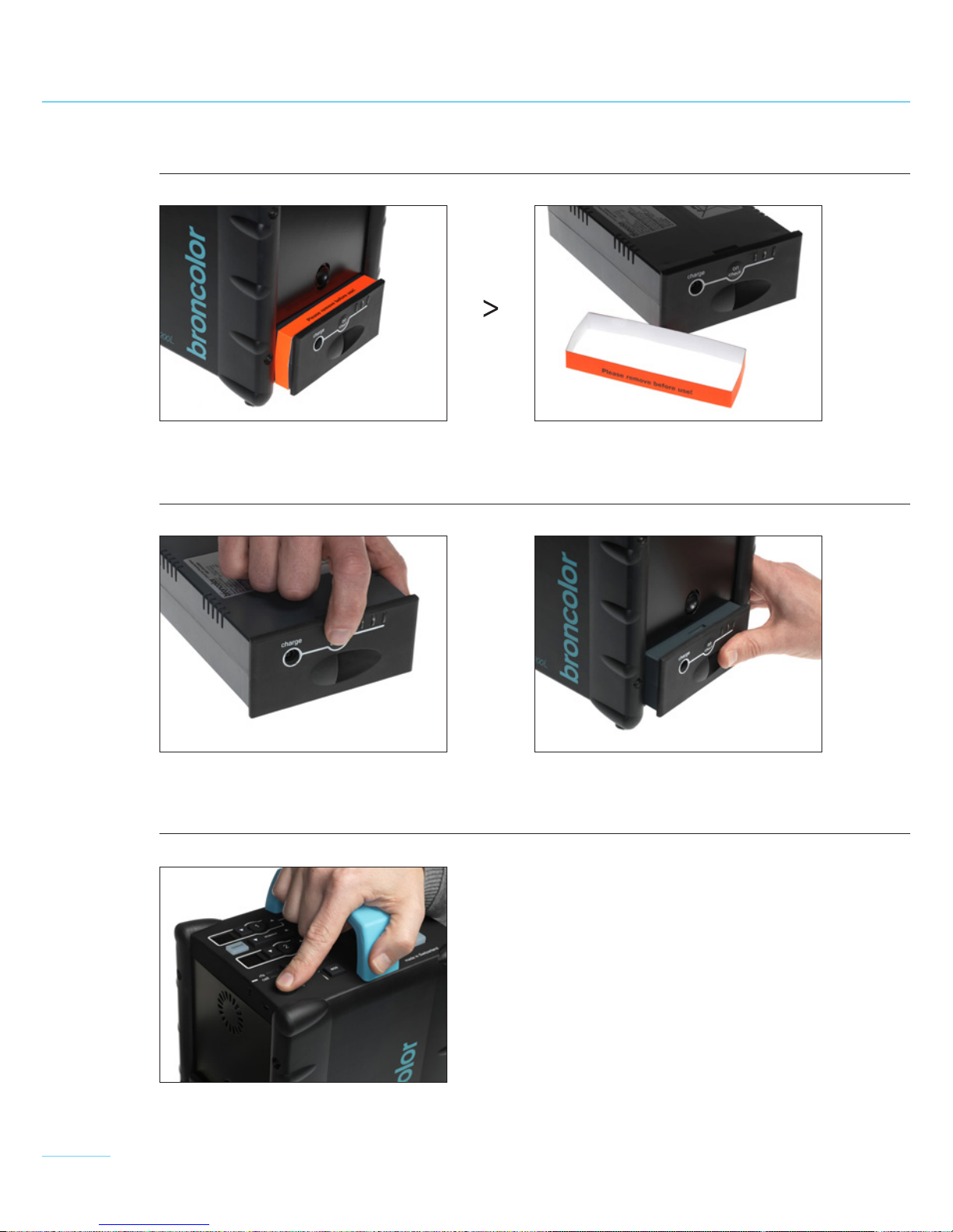
> Remove all transport protection and packing materials!
> Take special care of your equipment, particularly when there are children present! Never leave flash
equipment unattended!
> Like sunlight, flash light contains a certain amount of UV radiation! Using flash tubes or protecting
glasses that provide UV protection considerably reduces the undesirable side effects on skin
and
eyes! Nevertheless, when taking pictures at close range, avoid exposing unprotected skin and
eyes
to flashes! Eye contact with the light source should also be avoided! The maximum daily exposure
to UV radiation according to IEC 60335-2-27 / DIN 5031-10 is: 50 J / m
2
. This value must not be ex-
ceeded!
> The distance between a lamp and a person, or a lamp and an inflammable or heat-sensitive sur-
face must be at least 1 m to prevent damage due to thermal radiation!
> Switch off the power pack when connecting or disconnecting lamp plugs! The lamp plugs and sock-
ets
have mechanical interlocks! When plugging in, ensure that the interlocks engage completely!
To unplug, push down the locking spring below the cable guide and pull the plug out of its socket!
> Prior to replacing flash tubes, halogen lamps, protecting glasses, and fuses, disconnect the lamp
from the power pack! Allow the lamp to cool down for 10 minutes before replacing a halogen lamp
or flash tube!
> broncolor flash light systems should only be equipped with original broncolor flash tubes, original
broncolor combustible and packing material, original broncolor accessories, and original broncolor
spare parts!
> broncolor power packs, lamps and accessories meet extremely high safety standards! When bron-
color lamps are connected to power packs from other manufacturers, or broncolor power packs
to other brands’ lamps and accessories, built-in safety measures may become ineffective. Due to
different design features and contact assignment of the lamp plugs of other brands, there may
even be hazards for the user. Our guarantee is invalidated by the use of such unauthorised combi-
nations, and we accept no liability for damage arising from such use.
> Use only lamps which are expressly approved for operation with this power pack!
> To minimise the risk of fire, electric shock, or injury to persons use exclusively accessories recom-
mended by the manufacturer!
> Check that the mains voltage corresponds to the information on the charger’s type plate!
> The flash equipment is designed for use in dry conditions and in an ambient temperature between
-20°C and 65° C. Protect the flash equipment from moisture, condensation, dripping and splash
water, humidity, dirt, sand, metal chips, and the effects of dust!
> Protect the flash equipment from electromagnetic fields, shock and vibration! Protect the flash
equipment from heat and frost! If the power pack freezes, a permanent loss of power output and
serious technical damage may result!

7
> Sudden temperature differences may result in condensation forming inside the unit. In such situ-
ations allow the equipment to stand for at least one hour in a well-ventilated place to acclimatise
to the new temperature before startup!
> Do not operate the flash equipment in places where there is an explosion hazard!
> Do not use the power pack or lamps in or on water! Attention: high voltage!
> The power pack and lamps must not be immersed in water or other liquids! This could cause dan-
gerous
electric discharges!
> Before connecting a lamp to the power pack, the transport protection must be removed from the
front of the lamp!
> For safety reasons, never operate a lamp without the protecting glass in place! To protect eyes
against UV radiation, either a UV-coated protecting glass or a UV-coated lamp must be used.
> Before startup, the lamp must be mounted on a stand or suspended from a suitable mounting. When
a lamp is suspended, it must be secured to the mounting with the retaining screw
> For lamps, only sand-filled fuses of the type indicated on the safety type plate may be used! Sand-
filled fuses can be identified by their opaque body. If the wrong fuse is used, the lamp may burst.
> Filters or diffusers should not be fastened directly on to flash tubes, halogen modelling lamps, or
protecting glasses!
> Operate equipment and lamps only in the correct protective bag with ventilation slots!
> Cooling slots on the unit and lamps must never be covered.
> When laying, clearing away or rolling up cables, make sure they do not contact hot equipment or
parts of lamps, and that they do not cause a tripping hazard!
> Do not touch the lamp sockets on a power pack, and never insert a metallic object into a socket!
> Flash tubes, modelling lights, halogen lamps and protecting glasses operate at high temperatures.
This also applies to the front faces of lamps. Any accessory used on the front of a lamp also be-
comes very hot. Take great care when handling such accessories! Touching hot components can
cause injuries!
> When operating flash equipment, never touch glass or metal parts!
> Allow the unit and connected lamps to cool completely after use, before packing them!
> Remove the battery before you clean or service the unit!
> Equipment and lamps that have fallen over or been damaged must be checked by a competent
specialist before they are put back into service!
> To prevent dangerous electric shocks, never open a power pack or lamp! There may still be dan-
gerous voltages inside the unit. Units should only be opened, and all service and repair carried
out by an authorised broncolor Service station. Incorrect assembly can cause dangerous contact
voltages, even on connected units.
> For all MobiLED lamps with the serial numbers N08, N10, N12 and O04, it is compulsory that they
are modified in our Service station before use with the Move 1200 L power pack.

8
Shipping instructions:
> For transporting a power pack use the original broncolor packing!
Shipping instructions for lamps:
>
For transporting a lamp use the original broncolor packing! Before shipping fit the transport pro-
tection elements we supplied originally (foam elements and transport protection cover) to flash
tubes, halogen lamps and protecting glasses. If the transport protection elements are not all avail-
able,
remove the flash tubes, halogen lamps and protecting glasses and ship them separately.
IMPORTANT SAFETY INSTRUCTIONS

9
1. SCOPE OF SUPPLY
Move 1200 L power pack – 31.016.XX
Check whether the following items have been delivered:
Move 1200 L
Outdoor Kit 1 – 31.026.XX
Move 1200 L
Outdoor Kit 2 – 31.027.XX
Move 1200 L
Outdoor Para Kit – 31.028.XX
Move 1200 L (31.016.XX)
1 MobiLED (32.013.00)
Softbox Flex 70x70 (33.448.00)
RFS 2 Transmitter Kit (36.133.00)
Outdoor Trolley backpack (36.519.00)
Move 1200 L (31.016.XX)
2 MobiLED (32.013.00)
Softbox Flex 70x70 (33.448.00)
Umbrella 85 cm (33.574.00)
RFS 2 Transmitter Kit (36.133.00)
Outdoor Trolley backpack (36.519.00)
Move 1200 L (31.016.XX)
1 MobiLED (32.013.00)
RFS 2 Transmitter Kit (36.133.00)
Outdoor Trolley backpack (36.519.00)
Para 88 P Kit (33.483.00)
Power pack Move 1200 L Charger (36.151.XX) Protective bag (36.520.00)
Synchronisation cable (34.111.00) Continuous light adapter (36.129.00) Operating instructions (BA107.00)
Adapter cable Battery rechargeable, lithium (36.152.00)
> Kits
Move
Operating instructions | Bedienungsanleitung | Mode d‘emploi

10
2. STARTUP
1. Remove transport protection
2. Press the "on/ check" key 3. Click the battery into place
4. Switch on the power pack

11
3. OPERATING ELEMENTS
Key Function
On/ Off (1)
Switches the unit on and off.
Sync socket /
Mini USB (2)
For release via the sync cable, or software update
via Mini USB (only possible in Service station).
Speed (3)
For fast charging and flash times. See explanation
in Chapter 8.
Lamp connection 1
or 2 (5.1, 5.2)
Switches the appropriate lamp circuit on and off
Energy regulation
channel 1 (6)
Changes the flash energy in channel 1.
Press briefly to change by 1/ 10, long press by
1/ 1 f-stops.
Energy regulation
channel 2 (7)
Changes the flash energy in channel 2.
Press briefly to change by 1/ 10-, long press by
1/ 1 f-stops.
Output control (8) The flash energy of both channels is changed
together.
Modelling-light On/ Off (9) Switches the modelling light of both channels on
and off. The info display tells you the duration
until the modelling light switches off automatically
to save power (example: mod10s > modelling light
is on for 10 seconds).
Eco operation (10) When Eco is activated, the charging time is twice
as long. At the same time the number of flashes
per battery charge increases.
Sync (11)
Permits the selection of different methods of release.
1 x press > Release by photocell
2 x press > release by RFS 2
3 x press > Release by photocell and/ or RFS 2
Selection key (14) Use the key to scroll between the various menu
functions.
Menu and acknowledge-
ment key (15)
Use the key to go from the info display to the
menu, and to confirm your selection in the menu.
There is an explanation of menu navigation in
Chapter 7
Test (16) A test is initiated and the blue "Ready" display
appears (as soon as the charge /discharge operation
has been completed).

12
4. INFODISPLAY
4 5
1 32
1 Energy level in Joules or Watt seconds
2 Total energy of both channels in f-stops
3 Flash time for each lamp (at t0.1)
4 Shows the parameter setting. For details of menu navigation, see Chapter 7
seq – displayed as soon as a sequence is selected in the menu
mod – shows the selected modelling light duration
st – displays the selected studio address for radio release
opt/ min – displays the flash speed mode selected
5 State of battery charge display (13)
The display shows the approximate state of charge as follows:
The battery charge display blinks to indicate a low state of charge. Once the warning message
"Battery low" appears, the power pack is no longer available for use and must be recharged. All
settings are saved and the power pack switches off after two minutes.
Please note: batteries can only withstand a limited number of charging cycles. Battery life and
the number of charging cycles vary according to the type of use and the settings. Depending on
how the power pack is used, the actual working life of the battery may be shorter than given.
The manufacturer offers no guarantee regarding the number of flashes and charging cycles. You
will find further instructions under "Battery care and maintenance".
100 % 90 % 70 % 50 % 30 % < 20 %

13
5. BATTERY
5.1 Description of display on the battery 1 2 3
During operation 123
Battery fully charged (100%)
Battery half-full (ca. 50%)
Battery almost empty (ca. 20%)
Battery empty, please recharge (ca. 5%)
During charging 123
Battery empty and is being recharged
Battery is 50% charged
Battery is 80% charged
Battery fully charged
Fault messages at battery 123
Battery temperature too high.
Allow battery to cool down.
Current draw too high.
Battery and power pack must be serviced.
Voltage too high.
Battery and charger must be serviced.
Battery display illuminated
Battery display blinks

14
5.2 Care of the lithium battery
During charging and discharging, the ambient temperature should be in the range 5° C– 35° C. Use
of the battery at very low temperatures (below –10° C) may result in a severe loss of output.
The battery has a deep-sleep mode and switches itself off after 72 hours unless it is inserted into
a power pack so as to protect it against deep discharge. In this way the energy stored in the battery
is retained even after months without use.
To wake up the battery after 72 hours without use, press the "On" key on the battery’s front panel.
The type of battery used does not have a "memory effect", and so does not have to be discharged
regularly. It is however important to remember that the battery must not be discharged too far.
The unit switches off automatically when the battery voltage is too low. However, because there is
a small leakage current even when the unit is switched off, we strongly recommend that the bat-
tery is recharged after use. The battery should be removed from the unit during long periods out
of use.
In particular, please observe the following important information on the subject of care and main-
tenance of the battery:
Important note: before the first startup, we recommend that you charge the battery. We also
recommend that you recharge the battery immediately after use, even if it is only partially dis-
charged.
Avoid discharging the battery completely!
You will find further information on care of the battery on our website under
"Download" > "battery & care".
5.3. Charging the battery
The battery can be charged either installed in the unit or outside it. The unit can be operated while
it is charging.

15
6. OVERVIEW OF MAIN MENU FUNCTIONS
When you switch the power pack on, the main menu screen appears. From there you have access
to various functions. The only menu language available is English.
1) To enter the main menu, press the "menu/enter" key (15).
2) Use the "q/p" buttons (14) to reach the menu item you want.
3) Confirm your choice with "menu/ enter" (15).
Display Selection options Description
modelling light 10 s
30 s
60 s
cont
Time the modelling light is switched on to conserve
the battery. "cont" mode for continuous operation
sequence off
2– 50
Selection of a certain number of flash releases from
2– 50. As soon as this is activated, the infodisplay shows
the number in the selected sequence. (e.g.: seq15)
flash duration opt
min
Choice of flash duration
Opt: optimum colour temperature over entire
control range.
Min: fastest possible flash duration for selected energy
(explanation in Chapter 8)
studio address 1– 99 Assignment of studio address from 1– 99
audio ready signal on
off
Switches acoustic ready signal on or off

16
7. MENU NAVIGATION
On pressing the menu key (15), you enter the main menu of the power pack. From there you have
access to the various functions.
Example: Change the time the modelling light is on from 10 s to continuous operation
1) Press the menu key (15) to enter the main menu.
2) Use the selection key (14) to scroll down to the menu item "modelling light".
3) Press menu key (15) again to select the function.
The display begins to blink.
4) Press the selection key (14) repeatedly until "cont" (continuous operation) appears..
5) Confirm the selection by pressing the menu key (15) once.
You can return to the infodisplay by pressing the menu key again.
1) 2) 3)
4) 5)

17
1) 2) 3)
4) 5)
8. CONTROLLING FLASH TIMES
With the Move 1200 L power pack, you can control the flash time in two different ways:
8.1 Controlling flash times using the Speed key
Pressing the Speed key (3) reduces both the flash duration and the charging time for the power
pack. In this way Move power packs are optimised for photographing moving objects and / or rapid
image sequences.
As soon as the Speed key is pressed, the appropriate LED shows blue and the maximum flash
energy is restricted to 600 J. In speed mode the colour temperature is slightly colder, but remains
constant over the energy setting range.
8.2 Controlling flash times with the "flash duration" setting in the main menu
In the main menu you can change the power pack’s flash times from "optimum" (opt) to "minimum"
(min). This setting calculates the fastest possible flash time for the chosen energy level. This also
causes the flash colour to shift slightly towards the blue region.
1) Press "menu /enter" (15) to go to the main menu.
2) Use the "q" key (14) to scroll down the main menu to "flash duration".
3) Confirm your selection with the "menu/ enter" key (15).
4) Use the "q/p" buttons (14) to select "opt" or "min".
5) Confirm this with the "menu/ enter" key (15).
1) 2) 3)
4) 5)

18
8.3 Overview of flash times for opt, speed and min
9. RELEASE
9.1 RFS 2 interface (Radio Frequency System)
Move power packs are supplied with RFS 2 installed as standard.
For RFS 2 flash control, the channel (studio address) must correspond to the transmitter’s RFS 2
channel. The channel (studio address) is defined in the LCD display under "studio address".
The RFS 2 transmitter is not included in the power pack’s scope of supply.
9.2 Photocell (cell)
The photocell can be switched on and off using the "sync" key (11). When it is active, the blue LED
beside the "cell" label is illuminated.
After the first flash of a sequence, the active photocell is deactivated, and the blue LED beside the
"sync" key (11) blinks. Pressing the "sync" key switches on the photocell again.
9.3 Sync socket (2)
The sync cables, 5 m (Art. No. 34.111.00) and 10 m (34.112.00), can be fitted to socket (2) for cable
release.
9.4 "test" key (16)
This key is used for manual release. A flash can be triggered as soon as 70% of the set energy
level is reached. The visual Ready indicator (16), on the other hand, only illuminates when 100% is
attained.
Flash times at t 0.1
Output In Joules/ Ws opt speed min
10 1200 1/ 375 s -1/375 s
9600 1/ 875 s 1/935 s 1/ 935 s
8300 1/ 1310 s 1/ 2150 s 1/ 2300 s
7150 1/ 2150 s 1/ 3250 s 1/ 4300 s
675 1/ 2620 s 1/ 4300 s 1/ 7500 s
538 1/ 3000 s 1/ 4600 s 1/ 8500 s
418 1/ 3750 s 1/ 5250 s 1/ 8500 s
391/ 5250 s 1/ 6500 s 1/ 8500 s
251/ 7000 s 1/ 8500 s 1/ 8500 s

19
10. SPECIAL FUNCTIONS
10.1 Reset ((works settings)
Press the "test" key (16) for 4 s. This resets all functions to the works settings. Resetting is ac-
knowledged with a double beep.
10.2 Submenu
To enter the submenu for the power pack, hold the "menu/ enter" key (15) pressed for 4 s.
Display Options Description
daily counter Number of flashes since the last reset
(reset with the "menu/ enter" key)
flash counter Number of flashes since the power pack
was shipped
energy unit J
Ws
Choice of unit for energy on the infodisplay
serial number Displays the serial number. Only for Service
country Displays the country code. Only for Service
Power time-out 16– 120 min Automatically switches the power pack
off after so many minutes without use.
prog.version Displays the program version. Only for Service
11. DISPLAY CODES
Meanings of display codes (4)
Example with lamp energy "8.7":
> "8.7" blinks Flash monitor has detected a misfire
> "--" Lamp connected but switched off
> " " No lamp connected
> "-o" No energy can be assigned (all available energy has already been used by the
other lamp outlet)

20
Acoustic fault indicator
If the flash fails to fire, a warning signal sounds for ca. 0.5 s and the display (2) for the appropriate
lamp blinks.
Acoustic signals
Beep sound:
End of charging or discharging
Double beep:
Energy demand above or below energy control setting via RFS 2 transmitter
Test key held pressed for 4 s (reset to works settings)
Message in display Description
Thermo 1 Charging circuit overheated
(cooling phase = 15 min)
Thermo 2 Capacitors overheated
(cooling phase = 60 min)
Thermo 3 Resistors overheated
(cooling phase = 3 min)
Thermo 4 Battery overheated
(cooling phase = 15 min)
Thermo 5 Battery overheated
(cooling phase = 20 min)
Accu low 20% Appears on reaching 20% energy
remaining in battery
Charge defect Unit must be sent to Service
for repair
Overvoltage Unit must be sent to Service
for repair
Defect lamp 1/lamp 2 Lamp 1 or Lamp 2 is defective
or not correctly connected
Use broncolor tubes Please use only original broncolor
flash tubes
12. INFORMATION AND FAULT SIGNALS

21
13. LAMP COMPATIBILITY
max. Energie Move 1200 L Comments
Mobilite
Mobilite 2
1600 J x
x
Modification required (Service)
MobiLED 1600 J xModification required (Service)
for serial numbers: N08, N10, N12, O04
Litos 2400 J -
Picolite 1600 J x* Flash yes, modelling light no
Primo 1600 J
Pulso F2/ Hazy 2
1600 J x* Flash yes, modelling light no
Pulso G 1600 J
Unilite 1600 J
1600 J x* Flash yes, modelling light no
Pulso G 3200 J
Unilite 3200 J
3200 J x* Flash yes, modelling light no
Pulso F4/ Hazy 4 3200 J x* Flash yes, modelling light no
Pulso Twin 2 x 3200 J x* Flash yes, modelling light no
Primo 3200 J x* Flash yes, modelling light no
Lightbar
Striplite
3200 J
3200 J
x* Flash yes, modelling light no
Pulso-Spot 4 3200 J x* Flash yes, modelling light no
Ringflash C
Ringflash P
3200 J
3200 J
x* Flash yes, modelling light no
Litestick 3200 J x*
Boxlite 40 (A3) 3200 J x* Flash yes, modelling light no
No. of flashes per sequence is
limited (see marking on lamp!)
Pulso 8/ Hazy 8 6400 J -
*with restrictions

22
14. MOBILED
The MobiLED lamp was developed to suit the Move 1200 L
power pack: exceptionally compact and light, MobiLED has a
tilt-and-swivel head for single-handed operation and an in-
tegral reflector mounting. The intelligent ventilation control
only switches on when the operating temperature demands
it. The unique design requires very little space for transport
and storage.
The continuous lighting mode of the Move 1200 L enables the
use of powerful LEDs for modelling light so as to create new
light design effects. Especially at the daylight colour temper-
ature
of 5500 K, it offers completely new possibilities for film
sequences.
Important note: all MobiLED lamps with the serial numbers N08, N10, N12 and O04 must be
modified in our Service station before use with the Move 1200 L power pack.
14.1 Replacing flash tubes
Before you change the flash tube, be sure to disconnect the lamp from the power pack! Plug-in
flash tubes are used.
To change a flash tube, remove the snap ring and take out the protecting glass. Then pull the flash
tube axially out of its socket. When replacing the flash tube make sure it is pushed in as far as it
will go. Finally replace the protecting glass and secure it with the snap ring. Protecting glasses are
available in the versions "UVE" art. no. 34.339.00 (5500 K) and "UVE matt" art. no. 34.340.00 (5500
K).
14.2 Lamp plugs
Lamp plugs and sockets are fitted with mechanical interlocks to prevent unintentional disconnec-
tion. To unplug, push down the locking spring below the cable guide and pull the plug out of its
socket.
14.3 Extension cable to MobiLED
The extension cable (3.5 m), available as an accessory under art. no. 34.150.00, is especially thin
and flexible. It is only intended for use with MobiLED, Mobilite and Mobilite 2. If the cable is used
with other lights, the modelling light and cooling fan will not operate.
14.4 Lamp fuses
Use only sand-filled fuses of the type indicated on the type plate!
Other manuals for Move 1200 L RFS 2
1
Table of contents
Other Broncolor Power Pack manuals

Broncolor
Broncolor Move 1200 L RFS 2 User manual

Broncolor
Broncolor Verso A2 rfs User manual

Broncolor
Broncolor Topas A2 Evolution User manual

Broncolor
Broncolor nano 2 User manual

Broncolor
Broncolor Scoro A2 User manual

Broncolor
Broncolor Nano a4 User manual

Broncolor
Broncolor Scoro A2 User manual

Broncolor
Broncolor Scoro S WiFi / RFS 2 User manual