8
Furthermore, by selecting the corresponding outlet, the control range of variation can be
extended by one f-stop (Nano 2), respectively 1,7 f-stop (Nano A4). Whole numbers
correspond to whole f-stop intervals, decimal places to tenth f-stop steps. Brief pressure
on the "up / down" keys changes the setting by a 1/10 interval, prolonged pressure by
1/1 f-stop interval. The energy display (10) then flashes until charging or discharging
has stabilized the new level.
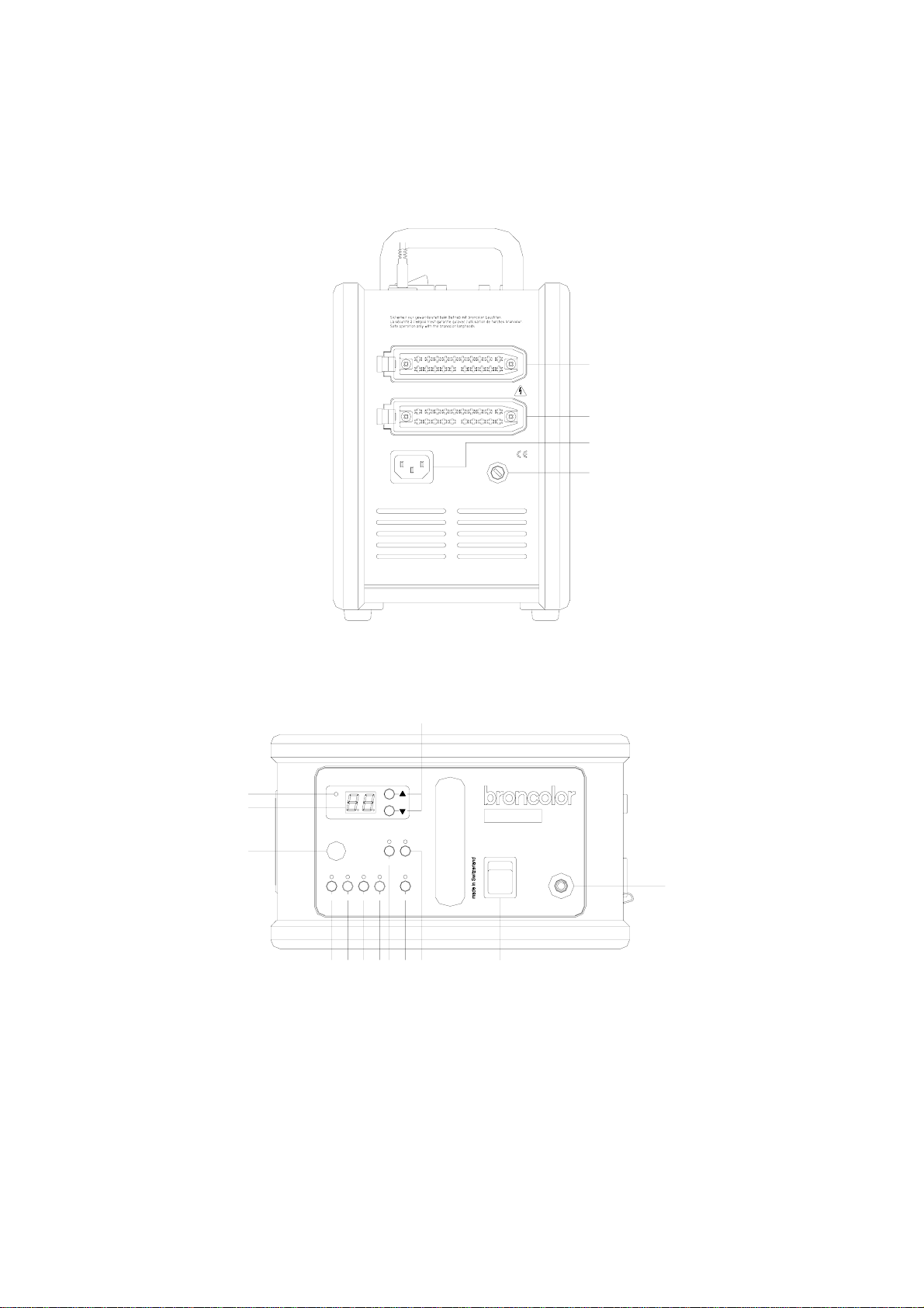
4. Lamp base outlets
With Nano 2 and Nano A4 the whole broncolor lamp base assortment is applicable
without restriction. The lamp base outlets (14.1 resp. 14.2) of the Nano units are marked
with the numbers 1 and 2. Nano 2 is designed for symmetrical energy distribution, Nano
A4 has an asymmetrical (individual) energy distribution. The lamp base outlet 1 allows
the triggering of 100% of the selected flash energy.
The flash capacitors of the Nano units are divided in two groups: 50% to 50%
symmetrically for Nano 2 and in the ratio 70% to 30% for Nano A4. If the power packs
are in use with only one lamp base, this type of design presents the advantage that up
to a maximum of 50% (Nano 2) or 30% (Nano A4) of the selected total energy can be
triggered over the lamp base outlet 2 (14.2) without needing to discharge the
superfluous energy over the outlet 1 (14.1). The fine adjustment is made by the flash
voltage. In this way the colour temperature with Nano 2 can be maintained constant
within a range of 3 f-stops and +/- 100 K without overcharging the flash capacitors. With
Nano A4 this range amounts to 3,7 f-stops.
5. Modelling light
5.1 General
The modelling light is switched on by the key "mod" (2) for all connected lamp bases.
When switched on, the green diode lights up. The lamp bases also have an additional
modelling light switch.
In chapter 8 you can find the instructions how to select the different operating modes
(modelling light proportionality).
5.2 Proportionality
The brightness of the modelling light can be set proportionally to the flash intensity. To
assure proportionality when operating units with different power output ratings, the units
have various proportionality levels. Proportionality is guaranteed if the identical prop
level has been set for all power packs. The higher the digit, the brighter the modelling
light. With the Nano power packs the proportionality refers to one single lamp base,
connected to outlet 1.